Fisher FIELDVUE DVC6200 Instruction Manual
Digital valve controller
Hide thumbs
Also See for FIELDVUE DVC6200:
- Quick start manual ,
- Instruction manual (148 pages) ,
- Mounting instructions (8 pages)
Table of Contents
Advertisement
Quick Links
DVC6200 Digital Valve Controller
Fisherr FIELDVUEt DVC6200
Digital Valve Controller
This manual applies to:
Instrument Level
AC, HC, AD, PD, ODV
Device Type
03
Device Revision
2
Hardware Revision
1
Firmware Revision
9, 10
DD Revision
3
Refer to Related Documents on page 3 for other documents containing
information related to DVC6200 digital valve controllers
www.Fisher.com
Introduction and Specifications
Viewing Device Variables and Diagnostics
Maintenance and Troubleshooting
Loop Schematics/Nameplates
Instruction Manual
D103409X012
September 2010
6
Installation
Basic Setup
Detailed Setup
Calibration
Parts
Appendices
Principle of Operation
Glossary
Index
1
2
3
4
5
6
7
8
9
A
A
B
C
Glossary
14
Index
Advertisement
Chapters
Table of Contents

Related Manuals for Fisher FIELDVUE DVC6200


Summary of Contents for Fisher FIELDVUE DVC6200
- Page 1 DD Revision Calibration Viewing Device Variables and Diagnostics Maintenance and Troubleshooting Parts Appendices Principle of Operation Loop Schematics/Nameplates Glossary Glossary Index Index Refer to Related Documents on page 3 for other documents containing information related to DVC6200 digital valve controllers www.Fisher.com...
- Page 2 DVC6200 Digital Valve Controller Field Communicator Fast-Key Sequence and Menu Trees Instrument Level HC, AD, PD, and ODV Fast-Key Fast-Key Function/Variable Coordinates Function/Variable Coordinates Sequence Sequence Actuator Style 1-2-6-4 Edit Feedback Connection 1-2-6-6 Alert Conditions End Point Control Enable 1-2-2-2-5-1 1-2-3-6-2 1-2-3-6-5-1 Alert Record Full Enable...
- Page 3 DVC6200 Digital Valve Controller Fast-Key Fast-Key Function/Variable Coordinates Function/Variable Coordinates Sequence Sequence Partial Stroke Test Variables 2-3-2 1-2-7-2 Temperature Minimum View/Edit 3-6-4 1-1-2 Temperature Sensor Shutdown 1-2-3-2-2 Performance Tuner 1-2-2-1-1-5 Temperature Units 1-2-5-2-2 Polling Address 1-2-5-1-7 Travel Pressure A 3-5-1 1-2-3-4-1 10-E Pressure B...
- Page 4 DVC6200 Digital Valve Controller Field Communicator Menu Tree for Instrument Level HC, AD, PD, and ODV Burst Mode Hot Key 1-2-1-4 1 Burst Enable 1 Instrument Mode 2 Burst Command 2 Control Mode 3 Cmd 3(Trending)Press 3 Protection Mode and Protection 4 Stabilize/Optimize Tuning 1 Instrument Mode...
- Page 5 DVC6200 Digital Valve Controller 1 Tvl Tuning Set Travel Tuning 1-2-2-1-1-1 2 Tvl Prop Gain 1 Tvl Tuning Set 1-2-2-1-1 3 Tvl Velocity Gain 2 Tvl Integ Enable 4 Tvl MLFB Gain 3 Tvl Integ Gain 4 Stabilize / Optimize Integral Settings 5 Performance Tuner 1-2-2-1-2...
- Page 6 DVC6200 Digital Valve Controller Instrument Level AC Fast-Key Fast-Key Function/Variable Coordinates Function/Variable Coordinates Sequence Sequence Actuator Style 1-1-2-2-4 1-1-2-3-2-2 Pressure Proportional Gain 1-2-3-4-1-2 Analog Input Calibration 1-3-1 Pressure Range Hi 1-2-3-5-1 Analog Input Range Hi 1-2-2-2 Pressure Range Lo 1-2-3-5-2 Analog Input Range Lo 1-2-2-3 1-1-2-3-2-1...
- Page 7 DVC6200 Digital Valve Controller Field Communicator Menu Tree for Instrument Level AC Hot Key 1 Instrument Mode Auto Setup 2 Protection 1 Setup Wizard Basic Setup 1-1-1 2 Relay Adjust 1 Auto Setup 3 Auto Travel Calib 2 Manual Setup Press &...
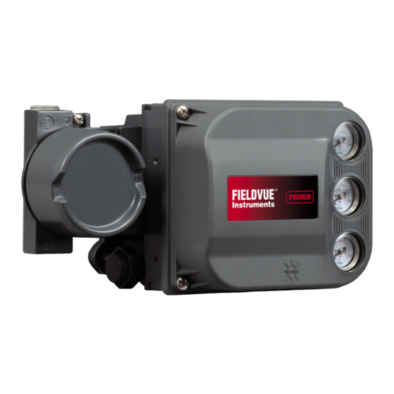
- Page 8 DVC6200 Digital Valve Controller W9713 THE FIELDVUE DVC6200 DIGITAL VALVE CONTROLLER IS A CORE COMPONENT OF THE PLANTWEBt DIGITAL PLANT ARCHITECTURE. THE DIGITAL VALVE CONTROLLER POWERS PLANTWEB BY CAPTURING AND DELIVERING VALVE DIAGNOSTIC DATA. COUPLED WITH VALVELINKt SOFTWARE, THE DVC6200 PROVIDES USERS WITH AN ACCURATE PICTURE OF VALVE PERFORMANCE, INCLUDING ACTUAL STEM POSITION, INSTRUMENT INPUT SIGNAL AND PNEUMATIC PRESSURE TO THE ACTUATOR.
-
Page 9: Table Of Contents
Introduction and Specifications Section 1 Introduction Scope of Manual ..........Conventions Used in this Manual . -
Page 10: Scope Of Manual
Supply Pressure Sensor Performance Diagnostics Solenoid Valve Testing Lead/Lag Input Filter 1. Refer to brochure part # D351146X012/D351146X412 for information on Fisher optimized digital valves for compressor antisurge applications. Scope of Manual This instruction manual includes specifications, installation, operating, and maintenance information... -
Page 11: Description
Note W9616 475 Field Communicator menu Figure 1-2. FIELDVUE DVC6200 Digital Valve Controller sequences used in this manual are for Integrally Mounted to a Fisher GX Control Valve instrument level HC, AD, PD, and ODV. -
Page 12: Educational Services
DVC6200 Digital Valve Controller D Bulletin 62.1:DVC6200 HC − Fisher FIELDVUE D Lock-in-Last Strategy − Supplement to Fisher DVC6200 Digital Valve Controller (D103423X012) FIELDVUE DVC6000 or DVC6200 Digital Valve Controller Instruction Manual (D103261X012) D Fisher FIELDVUE DVC6200 Digital Valve D Fisher HF340 Filter Instruction Manual... - Page 13 Introduction and Specifications Table 1-2. Specifications (2,3) Available Mounting Steady-State Air Consumption Integral mounting to the Fisher GX Control Standard Relay: Valve and Actuator System At 1.4 bar (20 psig) supply pressure: Less than 0.38 Integral mounting to Fisher rotary actuators...
- Page 14 Declaration of SEP The Gas Certified DVC6200 is FM, IECEx, and Fisher Controls International LLC declares this CSA Single Seal approved for use with natural product to be in compliance with Article 3 paragraph gas as the supply medium 3 of the Pressure Equipment Directive (PED) 97 / 23 / EC.
-
Page 15: Device Type
Introduction and Specifications Table 1-3. EMC Summary Results—Immunity Performance Criteria Port Phenomenon Basic Standard Test Level Point-to-Point Multi-drop Electrostatic discharge 4 kV contact IEC 61000-4-2 (ESD) 8 kV air 80 to 1000 MHz @ 10V/m with 1 kHz AM at 80% Radiated EM field IEC 61000-4-3 Enclosure... - Page 16 DVC6200 Digital Valve Controller September 2010...
- Page 17 ..........Mounting Fisher 67CFR Filter Regulator .
-
Page 18: Section 2 Installation
Maintenance section of this instruction manual. D Check with your process or W9643 Figure 2-1. FIELDVUE DVC6200 Digital Valve Controller safety engineer for any additional Mounted on a Fisher Sliding-Stem Valve Actuator measures that must be taken to protect against process media. -
Page 19: Iecex
Installation HOUSING FOR HOUSING FOR LINEAR AND ROTARY ACTUATORS FISHER GX ACTUATORS INTEGRAL OUTPUT PRESSURE PORT ROTARY NAMUR, M6 HOLE FOR LINEAR, M8 MOUNTING BOLT SLOTS FOR W9704 W9703 MOUNTING BOLTS Figure 2-2. Housing Configurations IECEx Mounting the DVC6200 The DVC6200 housing is available in two different... - Page 20 90 DEG SSTEM #50 ASSEMBLY (50 mm / 2 INCH) SSTEM #25 ASSEMBLY (25 mm / 1 INCH) (FISHER 2052 SIZE 2 & 3, 1051/1052 SSTEM #100 ASSEMBLY (100 mm / 4 INCH) SIZE 40-70, 1061 SIZE 30-100, SLIDING-STEM > 100 mm (4 INCHES)
- Page 21 DVC6200 quick start guide (D103410X012), available valve controller to a specific actuator. Refer to table at www.fisher.com or your Emerson Process 2-1 for the more common Fisher actuator mounting Management sales office. Table 2-1. DVC6200 Mounting Instructions Instructions for Mounting:...
-
Page 22: Mounting Fisher 67Cfr Filter Regulator
NOTE: SUPPLY CONNECTION APPLY LUBRICANT W9702 Figure 2-5. Mounting the Fisher 67CFR Regulator on a FIELDVUE DVC6200 Digital Valve Controller Mounting Fisher 67CFR Filter Regulator Yoke-Mounted Regulator Mount the filter regulator with two cap screws to the A 67CFR filter regulator, when used with a DVC6200 pre-drilled and tapped holes in the actuator yoke. -
Page 23: Pneumatic Connections
Installation Pneumatic Connections OUTPUT A CONNECTION WIRING TERMINAL BOX Pressure Pressure connections are shown in figure 2-6. All pressure connections on the digital valve controller are 1/4 NPT internal connections. Use at least 10 mm (3/8-inch) tubing for all pressure connections. If remote venting is required a minimum of 12.7 mm (1/2-inch) tubing should be used. -
Page 24: Output Connection
DVC6200 Digital Valve Controller Supply pressure must be clean, dry air that meets the Special Construction to Support Solenoid requirements of ISA Standard 7.0.01. A maximum 40 Valve Testing micrometer particle size in the air system is acceptable. Further filtration down to 5 micrometer particle size is recommended. - Page 25 Installation 24/48 VDC 110/220 VAC, etc. CONTROL SIGNAL (4-20 mA, 0-20 mA, 0-24 VDC) CONTROL LINE Port A Port B DVC6200 DIGITAL VALVE SUPPLY PRESSURE CONTROLLER WITH RELAY C MONITORING LINE NOTES: 1/4-18 NPT X 3/8 OD TUBING SPRING RETURN ACTUATOR ELECTRICAL WIRING Figure 2-7.
-
Page 26: Wiring And Electrical Connections
DVC6200 Digital Valve Controller Wiring and Electrical Connections SAFETY TALK− GROUND TALK+ WARNING Select wiring and/or cable glands that are rated for the environment of use (such as hazardous area, ingress protection and temperature). Failure to use properly rated wiring and/or cable glands can result in personal injury or property damage from fire or explosion. -
Page 27: Wiring Practices
Installation Wire the digital valve controller as follows, refer to figure 2-8: NON-HART BASED DCS 1. Remove the wiring terminal box cap (refer to figure 2-6). 2. Bring the field wiring into the terminal box. When applicable, install conduit using local and national HART electrical codes which apply to the application. -
Page 28: Voltage Available
DVC6200 Digital Valve Controller THUM ADAPTER TOTAL LOOP (IF USED) CABLE RESISTANCE COMPLIANCE VOLTAGE CONTROL SYSTEM VOLTAGE INTRINSIC SAFETY AVAILABLE AT HART BARRIER − FILTER − (if used) INSTRUMENT Calculate Voltage Available at the Instrument as Example Calculation follows: 18.5 volts (at 21.05 mA) Control system compliance voltage –... -
Page 29: Compliance Voltage
Installation Table 2-2. Cable Characteristics Capacitance Capacitance Resistance Resistance Cable Type pF/Ft pF/m Ohms/ft Ohms/m BS5308/1, 0.5 sq mm 61.0 0.022 0.074 BS5308/1, 1.0 sq mm 61.0 0.012 0.037 BS5308/1, 1.5 sq mm 61.0 0.008 0.025 BS5308/2, 0.5 sq mm 121.9 0.022 0.074... -
Page 30: Maximum Cable Capacitance
DVC6200 Digital Valve Controller START HERE Unpack the Install the HART HART Tri-Loop Tri-Loop. See HART Tri-Loop Configure the product manual HART Tri-Loop Review the HART to receive digital Tri-Loop Product valve controller Manual burst commands Mount the HART Tri-Loop to the DIN rail. - Page 31 Installation Commissioning the Digital Valve Controller for use with the HART Set the Burst Operation (1-2-1-4) Tri-Loop Signal Converter 1. From the Online menu, select Configure / Setup, To prepare the digital valve controller for use with a Detailed Setup, Mode and Protection, and Burst 333 HART Tri-Loop, you must configure the digital Mode.
- Page 32 DVC6200 Digital Valve Controller September 2010...
- Page 33 Basic Setup Section 3 Basic Setup Instrument Mode ..........Configuration Protection .
-
Page 34: Instrument Mode
DVC6200 Digital Valve Controller WARNING Instrument Mode If the jumper is removed too soon, To setup and calibrate the instrument, the instrument and auto calibration begins, the valve mode must be Out Of Service. will move full stroke. To avoid personal injury and property damage To view the instrument mode, press the Hot Key and caused by the release of pressure or... -
Page 35: Setup Wizard
Basic Setup mounts the digital valve controller and sets up the double-acting without spring, piston single-acting with instrument as specified on the order. When mounting spring, piston double-acting with spring), to a valve in the field, the instrument needs to be Valve style (rotary or sliding-stem), setup to match the instrument to the valve and On Loss of Instrument Signal (valve opens or... -
Page 36: Performance Tuner
It can be used with digital valve set (e.g., F to G). controllers mounted on most sliding-stem and rotary actuators, including Fisher and other manufacturers’ If after selecting Decrease Response or Increase products. Moreover, because the Performance Tuner... - Page 37 Detailed Setup Section 4 Detailed Setup Menu and Quick Key Sequence Tables ..... . Front Cover Detailed Setup ..........Mode and Protection .
- Page 38 DVC6200 Digital Valve Controller Pressure Control Pressure Range Hi Pressure Range Lo End Point Pressure Control End Point Control Enable PST Start Point Pressure Set Point Pressure Sat Time Input Characterization ........... . Define Custom Characterization .
-
Page 39: Parts
Detailed Setup Travel Cutoff Alerts Travel History Alerts ............Cycle Count Cycle Count/Travel Accumulator Deadband Travel Accumulator... -
Page 40: Detailed Setup
DVC6200 Digital Valve Controller Detailed Setup (1-2) Table 4-1. Default Detailed Setup Parameters Setup Parameter Default Setting Control Mode Analog Restart Control Mode Resume Last Zero Power Condition Valve Open Analog In Range Low 4 mA Note Analog In Range High 20 mA Analog Input Units Rotary −... -
Page 41: Control Mode
Detailed Setup D Burst Mode Table 4-1. Default Detailed Setup Parameters (continued) Default Setup Parameter Setting Instrument Time Invalid Enable Enabling burst mode provides continuous Calibration in Progress Enable communication from the digital valve controller. Burst Autocalibration in Progress mode applies only to the transmission of burst mode Enable data (analog input, travel target, pressure, and travel) Diagnostics in Progress Enable... -
Page 42: Protection
DVC6200 Digital Valve Controller Protection Table 4-2. Gain Values for Preselected Travel Tuning Sets Tuning Minor Loop Proportional Gain Velocity Gain D Protection Feedback Gain Some setup parameters may require changing the protection with the Field Communicator. To remove protection (change protection to None) requires placing a jumper across the Auxiliary terminals in the 4.85 terminal box in order to change protection. - Page 43 Detailed Setup Table 4-3. Conditions for Modifying FIELDVUE DVC6200 Digital Valve Controller Parameters In Service/ In Service/ Out of Service/ Out of Service/ Parameters Config Protected Config Unprotected Config Protected Config Unprotected Control Mode Restart Ctrl Mode - - -...
-
Page 44: Stabilize/Optimize
DVC6200 Digital Valve Controller Table 4-3. Conditions for Modifying FIELDVUE DVC6200 Digital Valve Controller Parameters (Continued) In Service/ In Service/ Out of Service/ Out of Service/ Parameters Config Protected Config Unprotected Config Protected Config Unprotected Flash ROM Fail - - -... -
Page 45: Integral Settings
Detailed Setup apparent in the travel response, it can generally Table 4-4. Gain Values for Preselected Pressure Tuning Sets optimize tuning more effectively than manual tuning. Pressure Pressure Tuning Pressure Typically, the performance tuner takes 3 to 5 minutes Integrator Minor Loop Proportional Gain to tune an instrument, although tuning instruments... - Page 46 1051 & 1052 Spring & Diaphragm Away from the top of the instrument 60, 70 Depends upon pneumatic connections. See Fisher 1061 Piston Dbl w/o Spring description for Travel Sensor Motion 68, 80, 100, 130 Depends upon pneumatic connections. See...
- Page 47 Detailed Setup pressure control until Travel Pressure Select is ranged travel) for the valve. During operation, the changed to Travel or Travel with Pressure travel target will not exceed this limit. When a Fallback/Auto recovery. It is not necessary to Travel Limit Low is set, the Travel Cutoff Low is enable the Travel Sensor Alert for Pressure deactivated, since only one of these parameters...
- Page 48 DVC6200 Digital Valve Controller point pressure control. Setting this value to Not Configured will disable partial stroke tests and end point pressure control. D Press Set Pt—Used in conjunction with End Point Pressure Control, Pressure Set Point allows the user to select a pressure to be delivered by the instrument at the travel extreme.
- Page 49 Detailed Setup Table 4-6. Typical Lead/Lag Filter Settings Parameter Description Typical Value First order time constant. A value of 0.0 will disable the Lag Time 0.2 sec lead-lag filter. Opening Lead/Lag Ratio Initial response to the filter in the opening direction. Closing Lead/Lag Ratio Initial response to the filter in the closing direction.
- Page 50 DVC6200 Digital Valve Controller D Drive Signal—Shows the value of the Configure / Setup, Detailed Setup, and Alerts. Follow the prompts on the Field Communicator display to instrument drive signal in % (percent) of maximum configure the following Alerts: Electronic Alerts, drive.
- Page 51 Detailed Setup D Environment Alerts D Travel Alerts (1-2-3-4) Supply Press Lo Alert (1-2-3-3-1) D Travel—Travel displays the actual position of the valve in percent (%) of calibrated travel. D Tvl Set Pt—Travel set point is the input to the Note characterization function.
- Page 52 DVC6200 Digital Valve Controller Deadband exceeded, ALERT IS SET new Reference Point established TRAVEL ALERT HIGH POINT TRAVEL ALERT DEADBAND ALERT IS CLEARED This amount of change is added to the Travel A6532/IL Deadband Reference Accumulator. Point Figure 4-2. Travel Alert Deadband Deadband (+/−...
-
Page 53: Travel History Alerts
Detailed Setup Deadband exceeded, and direction set point. Below this cutoff,the pressure target is changed, new Reference Point set to −23%. A Pressure Cutoff Lo of 0.5% is established recommended to help ensure maximum shutoff seat loading. Pressure Cutoff Lo is deactivated by setting it to −25.0% D Tvl Limit High—Travel Limit High defines the high limit for the travel in percent (%) of ranged... -
Page 54: Pressure Deviation Time
DVC6200 Digital Valve Controller D SIS Alerts (1-2-3-6) Table 4-7. Alerts Included in Alert Groups for Alert Record (Instrument Level ODV) Alert Group Alerts Include in Group Travel Lo Alert Travel Hi Alert Travel Lo Lo Alert Valve Alerts Travel Hi Hi Alert Travel Deviation Alert Drive Signal Alert Note... -
Page 55: Status
Detailed Setup Status (1-2-4) TRAVEL Select Configure / Setup, Detailed Setup, and Status. RANGE HIGH ZPC = OPEN Follow the prompts on the Field Communicator display to configure the following parameters: Instrument ZPC = CLOSED Time, Calibration and Diagnostics, Operational, and Integrator. -
Page 56: Analog Input Range
DVC6200 Digital Valve Controller assign is automatically displayed when the Field correspond to Travel Range High, if the Zero Communicator establishes contact with the digital Power Condition is configured as closed. If the valve controller at power-up. Zero Power Condition is configured as open, Input Range High corresponds to Travel Range Low. -
Page 57: Relay Type
Detailed Setup Relay Type Loss of Electrical Power Single-Acting Direct (Relay C) Port A pressure to zero. Port A pressure to zero. Double-Acting (Relay A) Port B pressure to full supply. Port B pressure to full supply. Single-Acting Reverse (Relay B) Figure 4-6. -
Page 58: Partial Stroke
DVC6200 Digital Valve Controller Point), and End Pt Contrl Enab (End Point Control Enable). Note Max Travel Movement—The default value for Max Travel Movement is 10%. It may be set to a value As a general rule, do not use less than between 1 and 30% in 0.1% increments. - Page 59 Detailed Setup Table 4-9. Values for Disabling Partial Stroke Pressure Limit Partial Note Zero Partial Stroke Actuator Relay Type Power Stroke Pressure Type Limit Condition Start Point In order to manually set the partial (Disabled) stroke pressure limit with the correct Open value, you must be able to run a valve Closed...
- Page 60 DVC6200 Digital Valve Controller Table 4-10. Estimates for Partial Stroke Pressure Limits Zero Power Actuator Style Relay Type PST Starting Point Partial Stroke Pressure Limit Condition Pmin − 0.25 * (Bench Set High − Bench Set Low) Open Closed Pmax + 0.25 * (Bench Set High − Bench Set Low) Closed A or C Pmax + 0.25 * (Bench Set High −...
- Page 61 Calibration Section 5 Calibration Calibration Overview ......... . . Calibrate .
-
Page 62: Calibration Overview
DVC6200 Digital Valve Controller Calibration Overview When a DVC6200 digital valve controller is ordered as Note part of a control valve assembly, the factory mounts the digital valve controller on the actuator and The Instrument Mode must be Out Of connects the necessary tubing, then sets up and Service and the Protection set to None calibrates the controller. -
Page 63: Manual Calibration
Calibration Table 5-1. Auto Calibrate Travel Error Messages Error Message Possible Problem and Remedy The analog input signal to the instrument must be greater than 3.8 mA. Adjust the current output Power failure occurred during Auto Calib from the control system or the current source to provide at least 4.0 mA. The problem may be one or the other of the following: 1. -
Page 64: Digital Calibration Adjust
DVC6200 Digital Valve Controller Digital Calibration Adjust Calibration using the Aux Terminal Connections From the Calibrate menu, select Travel Calibration, Manual Calibration and Digital Adjust. Connect a variable current source to the instrument Note LOOP + and LOOP − terminals. The current source should be set between 4 and 20 mA. -
Page 65: Supply Pressure Sensor Calibration
Calibration 1. Adjust the supply pressure regulator to the Supply Pressure Sensor maximum instrument supply pressure. Press OK. 2. The instrument reduces the output pressure to 0. The following message appears. Note Supply Pressure Sensor Calibration is Use the Increase and not available for instrument level HC. -
Page 66: Analog Input Calibration
DVC6200 Digital Valve Controller Analog Input Calibration (1-3-2-2) 8. From the adjustment menu, select the direction and size of adjustment to the displayed value. If the To calibrate the analog input sensor, connect a displayed value does not match the current source, variable current source to the instrument LOOP+ and press OK, then repeat this step (step 8) to further LOOP−... -
Page 67: Single-Acting Relays
Calibration FOR SINGLE-ACTING DIRECT RELAYS: ROTATE ADJUSTMENT DISC IN THIS DIRECTION UNTIL IT CONTACTS THE BEAM FOR DOUBLE-ACTING RELAYS: ROTATE ADJUSTMENT DISC IN THIS DIRECTION TO DECREASE OUTPUT PRESSURE ADJUSTMENT DISC FOR DOUBLE-ACTING RELAYS: ROTATE ADJUSTMENT DISC IN THIS DIRECTION TO INCREASE OUTPUT PRESSURE W9034 Figure 5-1. - Page 68 DVC6200 Digital Valve Controller September 2010...
-
Page 69: Viewing Device Variables And Diagnostics
Viewing Device Variables and Diagnostics Section 6 Viewing Device Variables and Diagnostics Device Diagnostics ..........Alert Conditions Status Device Record... - Page 70 DVC6200 Digital Valve Controller Device Diagnostics Flash ROM Alert—This alert indicates that the Read Only Memory integrity test failed. If this alert is indicated, restart the instrument and see if it clears. If it does not clear, replace the printed wiring board assembly.
-
Page 71: Viewing Device Variables And Diagnostics
Viewing Device Variables and Diagnostics Temperature Sensor Table 6-1. Alerts Included in Alert Groups for Alert Record Temperature Sensor Alert—This alert is indicated Alert Group Alerts Include in Group when the instrument temperature sensor fails, or the Travel Alert Lo sensor reading is outside of the range of −40 to 85_C Travel Alert Hi (−40 to 185_F). - Page 72 DVC6200 Digital Valve Controller D Ramp Open—ramps the travel toward open at Instrument Time the rate of 1.0% per second of the ranged travel. Inst Time Invalid D Ramp Closed—ramps the travel toward closed at Calibration and Diagnostics the rate of 1.0% per second of the ranged travel. Cal in Progress D Ramp to Target—ramps the travel to the Autocal in Progress...
-
Page 73: Viewing Device Variables And Diagnostics
Viewing Device Variables and Diagnostics scheduled in number of hours between tests. Any Example — 18AWG Unshielded Audio, Control power cycle will reset the test clock timer. and Instrumentation Cable Manufacturer’s specifications include: Auxiliary Terminal Nom. Capacitance Conductor to Conductor @ 1 KHz: 26 pF/ft The auxiliary terminal can be used for different Nom. - Page 74 DVC6200 Digital Valve Controller D Pressure Diff—Pressure Differential shows the Device Variables value of the output pressure differential in psi, bar, The following menus are available to define and/or kPa, or kg/cm view information about the instrument. From the D Supply Pressure—Supply Pressure displays the Online menu select Device Variables.
-
Page 75: Viewing Device Variables And Diagnostics
Viewing Device Variables and Diagnostics Table 6-2. Functions Available for Instrument Level Instrument Functions Available Note Level Communicates with the Field Communicator. Provides basic setup and calibration. Do not use the following raw travel Communicates with the Field Communicator and input indication for calibrating the ValveLink software. - Page 76 DVC6200 Digital Valve Controller September 2010...
- Page 77 Maintenance and Troubleshooting Section 7 Maintenance and Troubleshooting Replacing the Magnetic Feedback Assembly ..... Module Base Maintenance ........Tools Required .
- Page 78 DVC6200 Digital Valve Controller D Use bypass valves or completely The DVC6200 digital valve controller enclosure is rated NEMA 4X and IP66, therefore periodic cleaning shut off the process to isolate the valve of internal components is not required. If the DVC6200 from process pressure.
-
Page 79: Replacing The Magnetic Feedback Assembly
Maintenance and Troubleshooting Table 7-1. Tools Required CAUTION Tool Size Component Phillips Screwdriver Relay, printed wiring board When replacing components, use only assembly, and cover screws components specified by the factory. Hex key 5 mm Terminal box screw Always use proper component Hex key 1.5 mm Terminal box cover screw... -
Page 80: Replacing The Module Base
DVC6200 Digital Valve Controller MODULE BASE ASSEMBLY PRINTED WIRING BOARD ASSEMBLY TERMINAL CABLE HOUSING CABLE TO TRAVEL SENSOR W9913 TO TERMINAL BOX Figure 7-1. Printed Wiring Board Cable Connections Replacing the Module Base Refer to figure 8-2 key number locations. Note The module base is linked to the housing by two cable assemblies. -
Page 81: Submodule Maintenance
Maintenance and Troubleshooting Submodule Maintenance The digital valve controller’s module base contains the following submodules: I/P converter, PWB assembly, and pneumatic relay. If problems occur, these submodules may be removed from the module base and replaced with new submodules. After replacing a submodule, the module base may be put back into service. -
Page 82: Replacing The I/P Converter
DVC6200 Digital Valve Controller SHROUD BACK OF PWB ASSEMBLY (KEY 169) SUB-MODULE DIP SWITCH SOCKET-HEAD I/P CONVERTER SCREWS (4) (KEY 41) (KEY 23) DOWN BOOTS (KEY 210) TERMINAL BOX TRAVEL SENSOR W9328 CONNECTOR CONNECTOR PINS REMOVED FOR CONNECTOR KEYING. Figure 7-3. I/P Converter Figure 7-4. -
Page 83: Replacing The Printed Wiring Board Assembly
Maintenance and Troubleshooting Table 7-2. DIP Switch Configuration Operational Mode Switch Position Multidrop Loop Point-to-Point Loop DOWN 1. Refer to figure 7-4 for switch location. RELAY SEAL W8074 Replacing the Printed Wiring Board Figure 7-5. Pneumatic Relay Assembly Assembly and Setting the DIP Switch 1. -
Page 84: Terminal Box
DVC6200 Digital Valve Controller Perform the following procedure to replace the 3. Separate the module base from the housing by gauges, tire valves, or pipe plugs. Refer to figure performing the Removing the Module Base procedure. 8-2and 8-3 for key number locations. 4. -
Page 85: Checking Voltage Available
Maintenance and Troubleshooting 0.020 LOOP + / TEST + MULTIMETER TEST − (SEE NOTES BELOW) LOOP + / TEST + LOOP − − 4−20mA TEST − CURRENT SOURCE LOOP + / TEST + DCS SYSTEM (OR OTHER DVC6200 DIGITAL VALVE CURRENT SOURCE) CONTROLLER TERMINAL BOX NOTES:... - Page 86 DVC6200 Digital Valve Controller Table 7-3. Instrument Troubleshooting Symptom Possible Cause Action 1. Analog input reading at 1a. Control mode not Analog. 1a. Check the control mode using the Field Communicator. If instrument does not match in the Digital or Test mode, the instrument receives its set actual current provided.
- Page 87 Maintenance and Troubleshooting Table 7-3. Instrument Troubleshooting (Continued) Symptom Possible Cause Action 3d. I/P converter ass’y damaged/corroded/clogged. 3l. Check for bent flapper, open coil (continuity), contamination, staining, or dirty air supply. Coil resistance should be between 1680 - 1860 ohms. Replace I/P assy if damaged, corroded, clogged, or open coil.
- Page 88 DVC6200 Digital Valve Controller DVC6200 Troubleshooting Checklist 1. Instrument serial number as read from nameplate ________________________________________________ 2. Is the digital valve controller responding to the control signal? Yes _________ No _________ If not, describe ___________________________________________________________________________ 3. Measure the voltage across the “Loop −” and Loop +” terminal box screws when the commanded current is 4.0 mA and 20.0 mA: __________V @ 4.0 mA __________V @ 20.0 mA.
- Page 89 Parts Section 8 Parts Parts Ordering ..........Parts Kits .
- Page 90 Extreme Temperature option (fluorosilicone supplied by Emerson Process elastomers) 19B5401X022 Management should not, under any Extreme Temperature option (fluorosilicone circumstances, be used in any Fisher elastomers) Natural Gas Approved 19B5401X042 instrument. Use of components not supplied by Emerson Process I/P Converter Kit...
- Page 91 Parts Parts List Description Part Number Module Base (see figure 8-2) Note Module Base Drive Screw (2 req’d) Part numbers are shown for O-ring recommended spares only. For part Label, Shield Assembly numbers not shown, contact your Pipe Plug, hex socket (3 req’d) Emerson Process Management sales Slotted Pin (flame arrestor)
- Page 92 DVC6200 Digital Valve Controller Description Part Number GAS-BLOCKING Terminal Box PRESS-FIT ADAPTOR (see figure 8-2) Terminal Box Cap (1)(4) O-ring (1)(4) O-ring WIRING CONNECTOR Set Screw, hex socket, SST Cap Screw, hex socket, SST Terminal Box Assembly PWB Assembly (see figure 8-2) Note Contact your Emerson Process Management sales office for PWB Assembly FS numbers.
- Page 93 Parts HOUSING B—BACK VIEW HOUSING A—BACK VIEW (USED FOR ALL (USED FOR GX ACTUATOR) ACTUATORS EXCEPT GX) DOUBLE-ACTING DIRECT-ACTING REVERSE-ACTING GE40185 sheet 1 of 3 Figure 8-2. Housing Assembly (continued) September 2010...
- Page 94 DVC6200 Digital Valve Controller SECTION C−C SCALE 2 : 1 SECTION A−A SECTION E−E SCALE 2 : 1 SECTION F−F SCALE 2 : 1 GE40185 sheet 2 of 3 Figure 8-2. Housing Assembly (continued from previous page) DOUBLE-ACTING DIRECT-ACTING REVERSE-ACTING GE40185 sheet 3 of 3 Figure 8-3.
- Page 95 Principle of Operation A-A- Appendix A Principle of Operation HART Communication ......... . DVC200 Digital Valve Controller .
- Page 96 DVC6200 Digital Valve Controller +0.5V CONTROL SYSTEM ANALOG SIGNAL −0.5V HART MODEM 1200 Hz 2200 Hz “1” “0” AVERAGE CURRENT CHANGE DURING COMMUNICATION = 0 A6174/IL FIELD TERM. Table A-1. HART Frequency Shift Keying Technique HART Communication The HART (Highway Addressable Remote Transducer) protocol gives field devices the capability of communicating instrument and process data E1362...
- Page 97 OUTPUT B VALVE AND ACTUATOR VENT E1361 Figure A-3. FIELDVUE DVC6200 Digital Valve Controller Block Diagram and the output B pressure decreases. The output A prevent any further increase in nozzle pressure. pressure is used for double-acting and single-acting direct applications. The output B pressure is used for As the input signal decreases, the drive signal to the double-acting and single-acting reverse applications.
- Page 98 DVC6200 Digital Valve Controller HOUSING PNEUMATIC GAUGES RELAY COVER TERMINAL BOX WITH COVER PRINTED WIRING BOARD ASSEMBLY MODULE BASE ASSEMBLY I/P CONVERTER W9914 Figure A-4. FIELDVUE DVC6200 Digital Valve Controller Assembly September 2010...
- Page 99 Loop Schematics/Nameplates B-B- Appendix B Loop Schematics/Nameplates ............
- Page 100 DVC6200 Digital Valve Controller This section includes loop schematics required for wiring of intrinsically safe installations. It also contains the approvals nameplates. If you have any questions, contact your Emerson Process Management sales office. HAZARDOUS LOCATION NON-HAZARDOUS LOCATION CLASS I, DIV 1, GROUPS A,B,C,D CLASS II, DIV 1, GROUPS E,F,G CLASS III DVC6200...
- Page 101 Loop Schematics/Nameplates NON-HAZARDOUS LOCATION HAZARDOUS LOCATION I.S. CLASS I,II,III, DIV 1, GROUPS A,B,C,D,E,F,G N.I. CLASS I, DIV 2, GROUPS A,B,C,D DVC6200 Vmax = 30 VDC Imax = 226 mA Ci = 5 nF FM APPROVED BARRIER Li = 0.55 mH Pi = 1.4 NOTE 1, 3, 4, 5, 6 NOTE 7...
- Page 102 DVC6200 Digital Valve Controller HAZARDOUS LOCATION NON-HAZARDOUS LOCATION ZONE 0, Ex ia IIC DVC6200 Vmax = 30 VDC Imax = 226 mA Ci = 5 nF IECEx APPROVED BARRIER Li = 0.55 mH Pi = 1.4 NOTE 1, 3, 4 NOTE 5 NOTES: THE ENTITY CONCEPT ALLOWS INTERCONNECTION OF INTRINSICALLY SAFE APPARATUS TO ASSOCIATED APPARATUS NOT SPECIFICALLY EXAMINED IN SUCH...
- Page 103 Glossary Glossary Alert Point Byte An adjustable value that, when exceeded, A unit of binary digits (bits). A byte consists of activates an alert. eight bits. Calibration Location Algorithm Where the instrument was last calibrated; either A set of logical steps to solve a problem or in the factory or in the field.
- Page 104 DVC6200 Digital Valve Controller Controller Device Revision A device that operates automatically to regulate a Revision number of the interface software that controlled variable. permits communication between the Field Communicator and the instrument. Drive Signal Current-to-Pressure (I/P) Converter The signal to the I/P converter from the printed An electronic component or device that converts wiring board.
- Page 105 Out of Service: The instrument output does not Hardware Revision change in response to analog input changes Revision number of the Fisher Controls when the instrument mode is Out of Service. instrument hardware. The physical components Some setup parameters can be changed only of the instrument are defined as the hardware.
- Page 106 DVC6200 Digital Valve Controller Memory Pressure Sensor A type of semiconductor used for storing A FIELDVUE instrument internal device that programs or data. FIELDVUE instruments use senses pneumatic pressure. The DVC6200 has three types of memory: Random Access Memory three pressure sensors: one to sense supply (RAM), Read Only Memory (ROM), and pressure and two to sense the output pressures.
- Page 107 Glossary Seat Load Travel Accumulator Alert Point Force exerted on the valve seat, typically An adjustable value which, when exceeded, expressed in pounds force per lineal inch of port activates the Travel Accumulator Alert. Valid circumference. Seat load is determined by shutoff entries are 0% to 4 billion %.
- Page 108 DVC6200 Digital Valve Controller Travel Cutoff Travel Range Defines the cutoff point for the travel, in percent Travel, in percent of calibrated travel, that of ranged travel. There are two travel cutoffs: corresponds to the input range. high and low. Once travel exceeds the cutoff, the drive signal is set to either maximum or minimum, Travel Sensor depending on the Zero Control Signal and if the...
- Page 109 Index Index Auto Calibration, 54 Auto Partial Stroke Test, 64 Actuator Compatibility, 6 Aux Terminal Alerts, 43 Actuator Style, 49 Aux Terminal Mode, auto calibration, 26 Alert Conditions, 62 Auxiliary Terminal Alert Record, 63 Partial Stroke Test, 65 Electronics, 62 Wiring Length Guidelines, 65 Environment, 63 Sensor, 62...
- Page 110 DVC6200 Digital Valve Controller Wiring, 18 Electronic Alerts, 42 Drive Signal Alert, 42 Construction Materials, DVC6200, 6 Processor Impaired Alerts, 42 Control Mode, 33 Electronics, Alert Conditions, 62 EMC Summary Results, Immunity, 7 hazardous area approvals, 6, 10 End Point Pressure Control, 39 hazardous area classifications, 7 Loop Schematic, 92 Environment, Alert Conditions, 63...
- Page 111 Index Hazardous Area Classifications Loop Schematic CSA, 6, 7, 10 CSA, 92 FM, 93 FM, 6, 7, 10 IECEx, 94 IECEx, 6, 7, 11 Humidity Testing Method, 6 Magnet Assemblies, 12 Magnetic Feedback Assembly, replacing, I/P Converter Maintenance maintenance, 73 Gauges, Pipe Plugs, or Tire Valves, 75 removing, 73 I/P Converter, 73...
- Page 112 DVC6200 Digital Valve Controller FM, 93 Principle of Operation IECEx, 94 DVC6200, 88 HART Communication, 88 natural gas, as supply medium, 15, 70 Printed Wiring Board Assembly Number of Power Ups, Device Record, 64 maintenance, 74 removing, 74 replacing, 75 Processor Impaired Alerts, 42 Protection, 26, 34 Output Pressure Sensor, Calibration, 56...
- Page 113 Index Stroke Valve, 64 Travel Tuning, 34 Performance Tuner, 36 Supply Pressure Lo Alert, 43 Stabilize/Optimize, 36 Supply Pressure Sensor, Calibration, 57 Travel Tuning Sets, Gain Values, 34 Travel/Pressure Control, 38 End Point Pressure Control, 39 Pressure Control, 39 Travel Limits, 39 Temperature Limits, Operating Ambient, Tvl/Press Cutoffs, 39 Tvl/Press Select, 38...
- Page 114 DVC6200 Digital Valve Controller Index September 2010...
- Page 116 Fisher, FIELDVUE, ValveLink, PlantWeb, PROVOX, Rosemount, Tri-Loop, DeltaV, RS3 and THUM are marks owned by one of the companies in the Emerson Process Management business division of Emerson Electric Co. Emerson Process Management, Emerson, and the Emerson logo are trademarks and service marks of Emerson Electric Co. HART is a mark owned by the HART Comunication Foundation. All other marks are the property of their respective owners.
Need help?
Do you have a question about the FIELDVUE DVC6200 and is the answer not in the manual?
Questions and answers