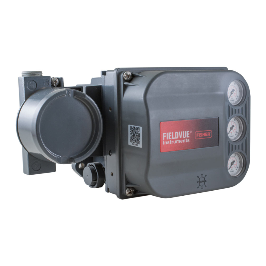
Fisher FIELDVUE DVC6200 Series, FIELDVUE DVC6200, FIELDVUE DVC6200f, FIELDVUE DVC6200p, FIELDVUE DVC6200 SIS Manual
- Instruction manual (148 pages) ,
- Quick start manual (44 pages) ,
- Mounting instructions (8 pages)
- Also fits for
- Fieldvue dvc6200
- Fieldvue dvc6200f
- Fieldvue dvc6200p
- Fieldvue dvc6200 sis
Advertisement
- 1 Before You Begin
- 2 Install the DVC6200 on the Valve
- 3 Connect the Pneumatic Tubing
- 4 Connect the Electrical Wires
-
5
Configure the Digital Valve Controller
- 5.1 Special Instructions for DVC6200 SIS
- 5.2 Special Instructions for DVC6200f PST
- 5.3 De-Energizeto Trip (DETT) DVC6200SIS, No Solenoid Valve
- 5.4 De-Energize to Trip (DETT) Digital Valve Controller and DETT Solenoid Valve
- 5.5 Energize to Trip (ETT) Digital Valve Controller and De-Energize to Trip (DETT) Solenoid Valve
- 5.6 Special Instructions for Solenoid Valve Health Monitoring
- 5.7 Wiring Configuration Option for Solenoid Valve Testing (DVC6200 SIS Only)
- 6 Documents / Resources
Before You Begin

 Do not install, operate or maintain a DVC6200 digital valve controller without being fully trained and qualified in valve, actuator and accessory Installation, Operation and Maintenance. To avoid personal injury or property damage, it is important to carefully read, understand and follow all contents of this Quick Start Guide, including all safety cautions and warnings. Refer to the appropriate Instruction Manual supplement listed below for hazardous area approvals and special instructions for "safe use" and installations in hazardous locations. If you have any questions about these instructions, contact your Emerson sales office before proceeding.
- CSA Hazardous Area Approvals: DVC6200 Series Digital Valve Controllers (D104203X012)
- FM Hazardous Area Approvals: DVC6200 Series Digital Valve Controllers (D104204X012)
- ATEX Hazardous Area Approvals: DVC6200 Series Digital Valve Controllers (D104205X012)
- IECEx Hazardous Area Approvals: DVC6200 Series Digital Valve Controllers (D104206X012)
All documents are available from your Emerson sales office or at Fisher.com. Contact your Emerson sales office for all other approval/certification information.
Avoid personal injury or property damage from sudden release of process pressure or bursting of parts. Before proceeding with any installation procedures:
- Always wear protective clothing, gloves and eyewear to prevent personal injury or property damage.
- Do not remove the actuator from the valve while the valve is still pressurized.
- Disconnect any operating lines providing air pressure, electric power or a control signal to the actuator. Be sure the actuator cannot suddenly open or close the valve.
- Use bypass valves or completely shut off the process to isolate the valve from process pressure. Relieve process pressure from both sides of the valve.
- Use lock‐out procedures to be sure that the above measures stay in effect while you work on the equipment.
- Check with your process or safety engineer for any additional measures that must be taken to protect against process media.
- Vent the pneumatic actuator loading pressure and relieve any actuator spring pre-compression so the actuator is not applying force to the valve stem; this will allow for the safe removal of the stem connector.
To avoid static discharge from the plastic cover when flammable gases or dust are present, do not rub or clean the cover with solvents. To do so could result in a spark that may cause the flammable gases or dust to explode, resulting in personal injury or property damage. Clean with a mild detergent and water only.
 NOTICE
Do not use sealing tape on pneumatic connections. This instrument contains small passages that may become obstructed by detached sealing tape. Thread sealant paste should be used to seal and lubricate pneumatic threaded connections.
Install the DVC6200 on the Valve
Housing Variations
The DVC6200 housing is available in two different configurations, depending on the actuator mounting method. Figure 1 shows the available configurations.

Figure 1. Housing Variations
General Mounting Guidelines
If ordered as part of a control valve assembly, the factory will mount the digital valve controller on the actuator and calibrate the instrument. If you purchased the digital valve controller separately, you will need a mounting kit. The following procedures are general guidelines. See the instructions that come with the mounting kit for detailed information on mounting the digital valve controller to a specific actuator model.
NOTICE
The magnet assembly material has been specifically chosen to provide a long‐term stable magnetic field. However, as with any magnet, care must be taken when handling the magnet assembly. Another high powered magnet placed in close proximity (less than 25 mm) can cause permanent damage. Potential sources of damaging equipment include, but are not limited to: transformers, DC motors, stacking magnet assemblies.
General Guidelines for use of High Power Magnets with Positioners
Use of high power magnets in close proximity to any positioner which is operating a process should be avoided. Regardless of the positioner model, high power magnets can affect the positioner's ability to control the valve.
Use of Magnetic Tools with the DVC6200
- Magnetic Tip Screw Drivers — Magnetic tip screw drivers can be used to work on the DVC6200. However, they should not be brought in close proximity to the magnet assembly (located at the back of the instrument) during process operations.
![]()
Calibrator Strap Magnets — These are high power magnets used to hold 4 to 20 mA calibrators. Normally, these calibrators would not be used while an instrument is controlling the process. High power magnets should be kept at least 15 cm / 6 in. from the DVC6200.

NOTE
- The mounting instructions also apply to the DVC6215 remote mount feedback unit.
- As a general rule, do not use less than 60% of the magnet assembly travel range for full travel measurement. Performance will decrease as the assembly is increasingly subranged.
- The linear magnet assemblies have a valid travel range indicated by arrows molded into the piece. This means that the hall sensor (the center point of the channel on the back of the DVC6200 housing) has to remain within this range throughout the entire valve travel. The linear magnet assemblies are symmetrical. Either end may be up.
- The magnet assembly may be referred to as a magnetic array in user interface tools.
- Mounting the instrument vertically, with the vent at the bottom of the assembly, or horizontally, with the vent pointing down, is recommended to allow drainage of moisture that may be introduced via the instrument air supply.
- Remote mount is not available with the DVC6200 SIS High Cv.
Sliding-Stem Linear Actuators
Bracket Mounted
Fisher 667 and 657
- Isolate the control valve from the process line pressure and release pressure from both sides of the valve body. Shut off all pressure lines to the actuator, releasing all pressure from the actuator. Use lock-out procedures to be sure that the above measures stay in effect while you work on the equipment.

Figure 2. Mounting Parts for Sliding‐Stem Actuator with up to 210 mm / 8.25 in. Travel - Attach the mounting bracket to the actuator.
- Loosely attach the feedback pieces and magnet assembly to the valve stem connector. Do not tighten the fasteners because fine adjustment is required.
![]()
Do not install a magnet assembly that is shorter than the physical travel of the actuator. Loss of control will result from the magnet assembly moving outside the range of the index mark in the feedback slot of the DVC6200 housing and may result in personal injury or property damage. - Using the alignment template (supplied with the mounting kit), position the magnet assembly inside the retaining slot.
- Align the magnet assembly as follows:
- For air-to-open actuators (e.g., Fisher 667) vertically align the magnet assembly so that the center line of the alignment template is lined up as close as possible with the upper extreme of the valid travel range on the magnet assembly. The magnet assembly should be positioned so that the index mark in the feedback slot of the DVC6200 housing is within the valid range on the magnet assembly throughout the range of travel. See Figure 3.

Figure 3. Air‐to‐Open Magnet Assembly Alignment - For air‐to‐close actuators (e.g., Fisher 657) vertically align the magnet assembly so that the center line of the alignment template is lined up as close as possible with the lower extreme of the valid travel range on the magnet assembly. The magnet assembly should be positioned so that the index mark in the feedback slot of the DVC6200 housing is within the valid range on the magnet assembly throughout the range of travel. See Figure 4.

Figure 4. Air‐to‐Close Magnet Assembly Alignment
- For air-to-open actuators (e.g., Fisher 667) vertically align the magnet assembly so that the center line of the alignment template is lined up as close as possible with the upper extreme of the valid travel range on the magnet assembly. The magnet assembly should be positioned so that the index mark in the feedback slot of the DVC6200 housing is within the valid range on the magnet assembly throughout the range of travel. See Figure 3.
- Tighten the fasteners and remove the alignment template.
![warning]() NOTE
NOTE
Use a flat end hex key to tighten the magnet assembly fasteners to a torque of 2.37 N•m / 21 lbf•in. for 4 mm screws and 5.08 N•m / 45 lbf•in. for 5 mm screws. For added security, especially in vibrating services, blue (medium) threadlocker may be used on the fasteners. - Mount the digital valve controller to the mounting bracket, using the mounting bolts.
- Check for clearance between the magnet assembly and the DVC6200 feedback slot.
![warning]() NOTE
NOTE
Ensure that there is clearance between the magnet assembly and the DVC6200 housing slot throughout the full range of travel. - For remote mount applications, proceed to "DVC6205 Remote Mount Base Unit Mounting" Section for DVC6205 base unit mounting. Otherwise, proceed to "Connect the Pneumatic Tubing" Section.


Actuators over 210 mm / 8.25 in. Travel
- Isolate the control valve from the process line pressure and release pressure from both sides of the valve body. Shut off all pressure lines to the pneumatic actuator, releasing all pressure from the actuator. Use lock‐out procedures to be sure that the above measures stay in effect while working on the equipment.

Figure 5. Mounting on Sliding‐Stem (Linear) Actuators over 210 mm / 8.25 in. Travel - Install the cam to the valve stem connector as described in the instructions included with the mounting kit.
- Install the mounting adaptor to the actuator.
- Attach the digital valve controller and mounting kit assembly to the mounting adaptor. The roller on the digital valve controller feedback arm will contact the actuator cam as it is being attached.

Figure 6. Roller Arm Variation used for Sliding‐Stem (Linear) Actuators Over 210 mm / 8.25 in. Travel - For remote mount applications, proceed to "DVC6205 Remote Mount Base Unit Mounting" Section for DVC6205 base unit mounting. Otherwise, proceed to "Connect the Pneumatic Tubing" Section.


Integral Mounted Fisher Actuators
- Isolate the control valve from the process line pressure and release pressure from both sides of the valve body. Shut off all pressure lines to the actuator, releasing all pressure from the actuator. Use lock‐out procedures to be sure that the above measures stay in effect while you work on the equipment.
- The DVC6200 digital valve controller mounts directly to an integral mounted Fisher actuator without the need for a mounting bracket. Make sure you have the correct DVC6200 housing for your actuator, as shown in Figure 1.
- For GX actuators, identify the yoke side to mount the DVC6200 digital valve controller based on the actuator fail mode. Refer to the GX Control Valve and Actuator System instruction manual.
- Loosely attach the feedback pieces and magnet assembly to the valve stem connector. Do not tighten the fasteners because fine adjustment is required.
![]()
Do not install a magnet assembly that is shorter than the physical travel of the actuator. Loss of control will result from the magnet assembly moving outside the range of the index mark in the feedback slot of the DVC6200 housing and may result in personal injury or property damage. - Using the alignment template (supplied with the mounting kit), position the feedback assembly inside the retaining slot.
- Continue on with the appropriate procedure below to align the magnet assembly.
Air‐to‐Open (667 size 30i to 76i and GX)
Vertically align the magnet assembly so that the center line of the alignment template is lined up as close as possible with the upper extreme of the valid travel range on the magnet assembly. The magnet assembly should be positioned so that the index mark in the feedback slot of the DVC6200 housing is within the valid range on the magnet assembly throughout the range of travel. See Figure 7.

Figure 7. Air‐to‐Open Magnet Assembly Alignment
NOTE:
(1) IMAGE DENOTES ACTUATOR AT HALF TRAVEL. ALIGN UPPER EXTREME OF MAGNET ASSEMBLY WITH ALIGNMENT TEMPLATE INDEX MARK.
- Tighten the fasteners and remove the alignment template.
![warning]() NOTE
NOTE
Use a flat end hex key to tighten the magnet assembly fasteners to a torque of 2.37 N•m / 21 lbf•in. for 4 mm screws and 5.08 N•m / 45 lbf•in. for 5 mm screws. For added security, especially in vibrating services, blue (medium) threadlocker may be used on the fasteners. - Remove the plug (R1/8) from the back of the DVC6200 housing. This pneumatic output port on the DVC6200 lines up with the integral actuator pneumatic port. See Figure 8.

Figure 8. Modifications for Integral Mounted Actuator; Air‐to‐Open Construction Only
![warning]() NOTE:
NOTE:
REAR HOUSING VIEW FOR GX ACTUATOR ILLUSTRATED. - Install the plug (1/4 NPT, included in the mounting kit) to the external output pneumatic port A.
- Attach the digital valve controller to the actuator mounting pad on the side that has the open pneumatic port. Be sure to place the O‐ring between the digital valve controller's pneumatic output and the actuator mounting pad. Pneumatic tubing is not required because the air passages are internal to the actuator.
![warning]() NOTE
NOTE
Use a 5 mm hex key to attach the digital valve controller the GX actuator mounting pad.
Use a 13 mm socket or box end wrench to attach the digital valve controller to the 667 size 30i to 76i actuator mounting pad. - Check for clearance between the magnet assembly and the DVC6200 feedback
- If not already installed, install a vent in the port on the upper diaphragm casing.
- For remote mount applications, proceed to "DVC6205 Remote Mount Base Unit Mounting" Section for DVC6205 base unit mounting. Otherwise, proceed to "Connect the Pneumatic Tubing" Section.
![warning]() NOTE
NOTE
Refer to the 667 Diaphragm Actuator Sizes 30/30i to 76/76i and 87 instruction manual for 667 product information.
Refer to the GX Instruction Manual for GX product information.

Air‐to‐Close (657 size 30i to 70i and GX)
Vertically align the magnet assembly so that the center line of the alignment template is lined up as close as possible with the lower extreme of the valid travel range on the magnet assembly. The magnet assembly should be positioned so that the index mark on the pole pieces (back of the DVC6200 housing) is within the valid range on the magnet assembly throughout the range of travel. See Figure 9.

Figure 9. Air‐to‐Close Magnet Assembly Alignment
- Tighten the fasteners and remove the alignment template.
![warning]() NOTE
NOTE
Use a flat end hex key to tighten the magnet assembly fasteners to a torque of 2.37 N•m / 21 lbf•in. for 4 mm screws and 5.08 N•m / 45 lbf•in. for 5 mm screws. For added security, especially in vibrating services, blue (medium) threadlocker may be used on the fasteners. - Attach the digital valve controller to the actuator mounting pad.
![warning]() NOTE
NOTE
Use a 5 mm hex key to attach the digital valve controller the GX actuator mounting pad.
Use a 13 mm socket or box end wrench to attach the digital valve controller to the 667 size 30i to 76i actuator mounting pad. - Check for clearance between the magnet assembly and the DVC6200 feedback slot.
- Install tubing between the actuator casing and the appropriate DVC6200 pneumatic output port.
- If not already installed, install a vent in the port on the lower diaphragm casing or yoke.
- For remote mount applications, proceed to "DVC6205 Remote Mount Base Unit Mounting" Section for DVC6205 base unit mounting. Otherwise, proceed to "Connect the Pneumatic Tubing" Section.
NOTE
When field converting a GX actuator from air-to-close to air-to-open (or vice‐versa), you will need to change the plugs for the pneumatic passages in the DVC6200 housing.
- To convert to air-to-open, remove the R1/8 pneumatic plug on the back of the DVC6200 housing and install an O‐ring. Plug the external pneumatic output with a 1/4 NPT plug. Refer to Figure 8.
- To convert to air-to-close, remove the external pneumatic plug. Install an R1/8 plug on the back of the DVC6200 housing. Install tubing between the pneumatic output connection of the DVC6200 to the pneumatic port on top of the actuator casing.
NOTE
Refer to the 667 Diaphragm Actuator Sizes 30/30i to 76/76i and 87 Instruction Manual for 667 product information.
Refer to the GX instruction manual for GX product information.
Quarter-Turn Rotary Actuators
Integral Mounted Fisher Actuators
- Isolate the control valve from the process line pressure and release pressure from both sides of the valve body. Shut off all pressure lines to the pneumatic actuator, releasing all pressure from the actuator. Use lock‐out procedures to be sure that the above measures stay in effect while working on the equipment.
- Verify that the appropriate cam is installed on the actuator as described in the instructions included with the mounting kit.

Figure 10. Mounting on Rotary Actuators

Figure 11. Rotary Actuator Mounting Variations
![warning]() NOTE THE DIFFERENCE IN THE SHAPE AND LENGTH OF THE ROLLER ARM.
NOTE THE DIFFERENCE IN THE SHAPE AND LENGTH OF THE ROLLER ARM. - Mount the DVC6200 on the actuator as follows:
- If required, a mounting adaptor is included in the mounting kit. Attach the adaptor to the digital valve controller, then attach the digital valve controller assembly to the actuator. The roller on the digital valve controller feedback arm will contact the actuator cam as it is being attached.
- If no mounting adaptor is required, attach the digital valve controller and mounting kit assembly to the actuator. The roller on the digital valve controller feedback arm will contact the actuator cam as it is being attached.
- For remote mount applications, proceed to "DVC6205 Remote Mount Base Unit Mounting" Section for DVC6205 base unit mounting. Otherwise, proceed to "Connect the Pneumatic Tubing" Section.


Bracket Mounted
The DVC6200 digital valve controller can be mounted to any quarter‐turn rotary actuator, as well as those that comply with the NAMUR guidelines. A mounting bracket and associated hardware are required. Refer to Figure 12.

Figure 12. Mounting on Quarter‐Turn Actuators
- Isolate the control valve from the process line pressure and release pressure from both sides of the valve body. Shut off all pressure lines to the actuator, releasing all pressure from the actuator. Use lock‐out procedures to be sure that the above measures stay in effect while you work on the equipment.
- Attach the magnet assembly to the actuator shaft. At mid‐travel, the flats on the magnet assembly should be approximately parallel to the channel on the back of the DVC6200 housing, as shown in Figure 13.

Figure 13. Magnet Assembly Orientation on Quarter‐Turn Actuators
![warning]() NOTE:
NOTE:
(1) THIS EXAMPLE SHOWS AN ACTUATOR WITH 90° TRAVEL. ON AN ACTUATOR THAT HAS LESS THAN 90° TRAVEL
THE MAGNET ASSEMBLY MAY NOT BE PARALLEL AT THE MID-TRAVEL POINT. TO VERIFY THE MAGNET ASSEMBLY POSITION IS IN WORKING RANGE, CONFIRM TRAVEL COUNTS ARE WITHIN THE EXPECTED RANGE OF 175 TO 3800 USING VALVE LINK SOFTWARE OR A FIELD COMMUNICATOR. - Install the mounting bracket on the actuator.
- Attach the digital valve controller to the mounting bracket using the 4 mounting bolts, as shown in Figure 12.
- Check for clearance between the magnet assembly and the DVC6200 feedback slot.
- For remote mount applications, proceed to "DVC6205 Remote Mount Base Unit Mounting" Section for DVC6205 base unit mounting. Otherwise, proceed to "Connect the Pneumatic Tubing" Section.

DVC6205 Remote Mount Base Unit Mounting
For remote‐mounted digital valve controllers, the DVC6205 base unit ships separately from the control valve and does not include tubing, fittings or wiring.
Pipestand Mounting
- Position a standoff on the back of the base unit.
- Using two 101.6 mm / 4 in. 1/4‐20 hex head screws loosely attach the base unit to the pipe stand with the mounting bracket.
- Position the second standoff, then using the remaining 101.6 mm / 4 in. hex head screws, securely fasten the base unit to the pipe stand.
- Tighten all screws.
- Proceed to "Connect the Pneumatic Tubing" Section.

Figure 14. FIELDVUE DVC6205 Pipestand Mounting

Wall Mounting
- Install the wall mounting screws by using the mounting bracket as a template.
- Install the mounting bracket to the back of the base unit using the spacers and screws provided in the mounting kit.
- Slide the assembly on the wall mounting screws and tighten.
- Proceed to "Connect the Pneumatic Tubing" Section.

Figure 15. FIELDVUE DVC6205 Wall Mounting

Connect the Pneumatic Tubing

Figure 16. Integral Mounting of a Fisher 67CFR Regulator on a FIELDVUE DVC6200 Digital Valve Controller
NOTES:
INTEGRAL MOUNTING OF FILTER REGULATOR IS NOT AVAILABLE FOR DVC6200 SIS HIGH CV.
(1) APPLY LUBRICANT
NOTICE
Do not use sealing tape on pneumatic connections. This instrument contains small passages that may become obstructed by detached sealing tape. Thread sealant paste should be used to seal and lubricate pneumatic threaded connections.
- Connect the DVC6200 pneumatic output to the actuator input using at least 10 mm /3/8 in. diameter tubing. Minimum inside diameter of tubing required for DVC6200 SIS High Cv, HCv1 is 7.11 mm / 0.28 in. HCv2 is 11.7 mm / 0.46 in. and HCv3 is 16.5 mm / 0.65 in.
- When using a single-acting direct digital valve controller (relay A or C) on a single-acting actuator, connect OUTPUT A to the actuator pneumatic input.
- When using a single-acting reverse digital valve controller (relay B) on a single-acting actuator, connect OUTPUT B to the actuator diaphragm casing.
- When using a double-acting digital valve controller (relay A) on a double-acting actuator, connect OUTPUT A and OUTPUT B to the appropriate actuator pneumatic input. With no input current to the DVC6200, OUTPUT A is at zero pressure and OUTPUT B is at full supply pressure when the relay is properly adjusted.
NOTE
To have the actuator stem extend from the cylinder with increasing input signal, connect OUTPUT A to the actuator cylinder connection farthest from the actuator stem. Connect OUTPUT B to the cylinder connection closest to the actuator stem. To have the actuator stem retract into the cylinder with increasing input signal, connect OUTPUT A to the actuator cylinder connection closest to the actuator stem. Connect OUTPUT B to the cylinder connection farthest from the actuator stem.
NOTE
Solenoid valves placed between the output of a DVC6200 digital valve controller and the input to an actuator require a minimum Cv of 0.49. Greater restrictions can affect the response of the assembly.
Supply medium must be clean, dry, oil-free and noncorrosive and meet the requirements of ISA Standard 7.0.01 or ISO 8573-1.
Severe personal injury or property damage may occur from an uncontrolled process if the instrument supply medium is not clean, dry, oil-free and noncorrosive. While use and regular maintenance of a filter that removes particles larger than 40 micrometers in diameter will suffice in most applications, further filtration down to 5 micrometer particle size is recommended. Lubricant content is not to exceed 1 ppm weight (w/w) or volume (v/v) basis. Condensation in the air supply should be minimized.
Check with an Emerson field office and industry instrument air quality standards for use with corrosive air or if you are unsure about the amount of air filtration or filter maintenance.
When using natural gas as the supply medium or for hazardous location applications, the following warnings also apply:
- Remove electrical power before removing the housing cap. Personal injury or property damage from fire or explosion may result if power is not disconnected before removing the cap.
- Remove electrical power before disconnecting any of the pneumatic connections.
- When disconnecting any of the pneumatic connections or any pressure retaining part, natural gas will seep from the unit and any connected equipment into the surrounding atmosphere. Personal injury or property damage may result from fire or explosion if natural gas is used as the supply medium and appropriate preventive measures are not taken. Preventive measures may include, but are not limited to, one or more of the following: ensuring adequate ventilation and the removal of any ignition sources.
- Ensure that all caps and covers are correctly installed before putting this unit back into service. Failure to do so could result in personal injury or property damage from fire or explosion.
- Connect a filter or filter regulator to the DVC6200 supply input using at least 10 mm / 3/8 in. diameter tubing. Minimum inside diameter of tubing required for DVC6200 SIS High Cv, HCv1 is 7.11 mm / 0.28 in. HCv2 is 11.7 mm / 0.46 in and HCv3 is 16.5 mm / 0.65 in.
![warning]() NOTE
NOTE
When using a DVC6200 SIS High Cv, ensure the capacity of the filter is at least four times the Cv of the instrument.- When using an integral mounted 67CFR filter regulator, lubricate an O-ring and insert it in the recess around the supply connection on the digital valve controller. Attach the filter regulator to the side of the digital valve controller. Thread a 1/4 in. socket-head pipe plug into the unused outlet on the filter regulator. This is the standard method of mounting the filter regulator. No tubing is required.
- When using a yoke mounted 67CFR filter regulator, mount the filter regulator with two cap screws to the pre-drilled and tapped holes in the actuator yoke. Thread a 1/4 in. socket-head pipe plug into the unused outlet on the filter regulator. No O-ring is required.
- When using a casing mounted filter regulator, use a separate casing mounting bracket (typically provided with the filter regulator). Attach the mounting bracket to the filter regulator and then attach this assembly to the actuator casing. Thread a 1/4 in. socket-head pipe plug into the unused outlet on the filter regulator. No O-ring is required.
- If the supply pressure is less than the maximum actuator and instrument pressure rating, a regulator is not required. However, a filter is always required. Attach the filter securely to the actuator or instrument.
![]()
Personal injury or property damage can occur from cover failure due to overpressure. Ensure that the housing vent opening is open and free of debris to prevent pressure build-up under the cover.
This unit vents the supply medium into the surrounding atmosphere. When installing this unit in a non-hazardous (non-classified) location in a confined area, with natural gas as the supply medium, you must remotely vent this unit to a safe location. Failure to do so could result in personal injury or property damage from fire or explosion and area re-classification.
When installing this unit in a hazardous (classified) location remote venting of the unit may be required, depending upon the area classification and as specified by the requirements of local, regional and national codes, rules and regulations. Failure to do so when necessary could result in personal injury or property damage from fire or explosion and area re-classification. In addition to remote venting of the unit, ensure that all caps and covers are correctly installed. Failure to do so could result in personal injury or property damage from fire or explosion and area re-classification.
- If necessary, remove the plastic vent on the DVC6200 (see Figure 17) and install a pipe away vent line using at least 12.7 mm / 1/2 in. diameter tubing. The vent line must be as short as possible with a minimum number of bends and elbows to prevent back pressure build-up.

Figure 17. Vent Connections
![warning]() NOTE
NOTE
If using a DVC6200 SIS High Cv, the muffler will need to be removed to install the pipe away vent. Minimum inside diameter of tubing required for HCv1 is 7.11 mm / 0.28 in. HCv2 is 11.7 mm / 0.46 in. and HCv3 is 16.5 mm / 0.65 in.
Ensure that a bug screen is installed at the open end of the pipe away vent.
![]()
To avoid personal injury or property damage resulting from bursting or parts, do not exceed maximum supply pressure. Personal injury or property damage may result from fire or explosion if natural gas is used as the supply medium and appropriate preventive measures are not taken. Preventive measures may include, but are not limited to, one or more of the following: Remote venting of the unit, re-evaluating the hazardous area classification, ensuring adequate ventilation and the removal of any ignition sources.
![warning]() NOTE
NOTE
The Gas Certified device option simplifies process sealing requirements when using natural gas as the supply medium. Instruments with the label shown in Figure 18 include a "Single Process Seal" and meet ISA 12.27.01 Single Sealed and IEC 60079-40 Process Sealed requirements. If natural gas is detected in the terminal box or connected conduit when using a Gas Certified DVC6200, through use of a gas leak detector or other method, the entire terminal box assembly must be replaced. Read and follow all local, regional and federal wiring requirements for natural gas installations. Contact your Emerson sales office for information on obtaining a Gas Certified DVC6200 digital valve controller.

Figure 18. Label for Natural Gas Certified Terminal Box - Connect the pneumatic supply line to the 1/4 NPT in connection on the filter regulator. Use an appropriate size supply line for the DVC6200 SIS High Cv.
![warning]() NOTE
NOTE
If using a solenoid valve in addition to the digital valve controller, install the solenoid valve in the pneumatic path between the digital valve controller output and the actuator input. - Proceed to "Connect the Electrical Wires" Section.


Connect the Electrical Wires
Select wiring and/or cable glands that are rated for the environment of use (such as hazardous area, ingress protection and temperature). Failure to use properly rated wiring and/or cable glands can result in personal injury or property damage from fire or explosion.
Wiring connections must be in accordance with local, regional and national codes for any given hazardous area approval. Failure to follow the local, regional and national codes could result in personal injury or property damage from fire or explosion. To avoid personal injury resulting from electrical shock, do not exceed maximum input voltage specified on the product nameplate. If the input voltage specified differs, do not exceed the lowest specified maximum input voltage.
Personal injury or property damage caused by fire or explosion may occur if electrical connections are attempted in a potentially explosive atmosphere or in an area that has been classified as hazardous. Confirm that area classification and atmosphere conditions permit the safe removal of the terminal box cover before proceeding.
The valve may move in an unexpected direction when power is applied to the digital valve controller. To avoid personal injury and property damage caused by moving parts, keep hands, tools and other objects away from the valve/actuator assembly when applying power to the instrument.
FOUNDATION Fieldbus™ or PROFIBUS PA Devices
Refer to the DVC6200f instruction manual or DVC6200p instruction manual for additional information.
The digital valve controller is normally powered over the bus from a power supply. Refer to the FOUNDATION Fieldbus or PROFIBUS site planning guide, available from your Emerson sales office, for proper wire types, termination, length, grounding practices, etc.
NOTE
To avoid the valve going to an unknown position when power is applied, the digital valve controller is shipped from the factory with the transducer block mode Out of Service.
Wire the digital valve controller as follows, refer to Figure 19.

Figure 19. Loop Connections Terminal Box
- Remove the wiring terminal box cap.
- Bring the field wiring into the terminal box. When applicable, install conduit using local and national electrical codes which apply to the application.
- The instrument is not polarity sensitive. Connect one wire from the controller output to one of the LOOP screw terminals in the terminal box shown in Figure 19. Connect the other wire from the controller output to the other LOOP screw terminal in the terminal box.
![]()
Personal injury or property damage can result from the discharge of static electricity. Connect a 14 AWG / 2.08 mm 2 ground strap between the digital valve controller and earth ground when flammable or hazardous gases are present. Refer to national and local codes and standards for grounding requirements. - Make connections to the ground terminal(s) following national and local codes and plant standards. As shown in Figure 19, two ground terminals are available for connecting a safety ground, earth ground or drain wire. The safety ground terminal is electrically identical to the earth ground.
- Screw the cap (key 4) onto the terminal box until no gap remains.
- Install the set screw (key 58) into the cap (key 4). Secure the cap by engaging the screw.
- Write the valve tag number on the top and bottom of the paper commissioning tag, as shown in Figure 20.

Figure 20. Paper Commissioning Tag - Remove the lower half of the paper commissioning tag and deliver it to the control system configurator. With the piece of paper, the control system configurator will be able to easily change the Device ID placeholder to the actual valve tag number.
![warning]() NOTE
NOTE
Alternatively, the valve tag number can be entered at the factory when specified at the time of order entry. When the valve tag number is electronically stored in the DVC6200, the control system will display the valve tag number instead of the Device ID. As a result, steps 7 and 8 will not be required. - For Remote Mount applications, proceed to "Remote Mount Feedback Unit" Section.
For DVC6200f PST applications, proceed to "Special Instructions for DVC6200f PST" Section
For Special Instructions for DVC6200f PST. Otherwise, proceed to "Configure the Digital Valve Controller" Section.

HART® Devices
Refer to the DVC6200 HW2 instruction manual or DVC6200 SIS Instruction Manual for additional information.
The digital valve controller is normally powered by a control system output channel. Shielded cable will ensure proper operation in electrically noisy environments.
Wire the digital valve controller as follows, refer to Figure 21:

Figure 21. Loop and Talk Connections
NOTE:
(1) FOR DVC6200 HW2 WITH I/O OPTION TIGHTEN TERMINAL BLOCK SCREWS TO A MAXIMUM TORQUE OF 0.79 N•m / 7 lbf•in.
- Remove the wiring terminal box cap.
- Bring the field wiring into the terminal box. When applicable, install conduit using local and national electrical codes which apply to the application.
- Connect the control system output channel positive wire to the LOOP+ screw terminal in the terminal box. Connect the control system output channel negative (or return) wire to the LOOP- screw terminal in the terminal box.
![]()
Personal injury or property damage can result from the discharge of static electricity.
Connect a 14 AWG / 2.08 mm 2 ground strap between the digital valve controller and earth ground when flammable or hazardous gases are present. Refer to national and local codes and standards for grounding requirements. - As shown in Figure 21, two ground terminals are available for connecting a safety ground, earth ground or drain wire. The safety ground is electrically identical to the earth ground. Make connections to these terminals following national and local codes and plant standards.
![warning]() NOTE
NOTE
Depending on the control system you are using, an HF340 HART filter may be needed to allow HART communication. The HART filter is a passive device that is inserted in field wiring from the HART loop. The filter is normally installed near the field wiring terminals of the control system I/O. Its purpose is to effectively isolate the control system output from modulated HART communication signals and raise the impedance of the control system to allow HART communication. For more information on the description and use of the HART filter, refer to the HF340 HART filter instruction manual. To determine if your system requires a HART filter, refer to the DVC6200 HW2 Instruction Manual or DVC6200 SIS Instruction Manual or contact your Emerson sales office. - Screw the cap (key 4) onto the terminal box until no gap remains.
- Install the set screw (key 58) into the cap (key 4). Secure the cap by engaging the screw.
- For applications that require a Position Transmitter or Discrete Switch ("Position Transmitter or Discrete Switch" Section), Remote Feedback Mounting ("Remote Mount Feedback Unit" Section), and/or THUM™ Adapter ("Smart Wireless THUM Adapter" Section) proceed to the appropriate section. For DVC6200 SIS applications proceed to "Special Instructions for DVC6200 SIS" Section. Otherwise, proceed to "Configure the Digital Valve Controller" Section.
Position Transmitter or Discrete Switch
The DVC6200 HART communicating device has an optional output circuit that can be configured as a 4 to 20 mA position transmitter or a discrete switch. Configuration of the output circuit requires the proper DIP switch electrical setting on the main electronics board (see Figure 22) and also must be enabled with a user interface tool. The DIP switch electrical setting is pre-configured at the factory when ordered properly.

Figure 22. OUTPUT Connections and Transmitter/Switch Settings
The position transmitter circuit derives its operating power from the control system input channel in the same manner as a 2-wire transmitter.
The discrete switch is a solid state circuit (1 A maximum) which opens and closes based on a user configurable trip point. The trip point can be based on valve travel anywhere within the calibrated travel range or based on a device alert. In order for the switch output to function, the digital valve controller must be powered. If power is lost, the switch will always go to the open state. The output circuit, whether operating as a transmitter or switch, is galvanically isolated from the position control loop circuit such that different ground references between the two circuits are allowed.
Wire the OUTPUT terminals as follows (refer to Figure 23):

Figure 23. FIELDVUE DVC6200 with Position Transmitter or Discrete Switch, Field Wiring Schematic
- Route the field wiring into the terminal box through the conduit connection.
- When applicable, install conduit using any local and national electrical codes that apply to the connection.
- Connect the control system input channel positive wire to the OUT (+) terminal. Connect the control system input channel negative wire to the OUT (-) terminal.
- Replace and hand tighten the cover on the terminal box.
- For applications that require Remote Feedback Mounting ("Remote Mount Feedback Unit" Section) and/or a THUM Adapter ("Smart Wireless THUM Adapter" Section) proceed to the appropriate section.
For DVC6200 SIS applications, proceed to Special Instructions for DVC6200 SIS in "Special Instructions for DVC6200 SIS" Section. Otherwise, proceed to "Configure the Digital Valve Controller" Section.
Remote Mount Feedback Unit
The DVC6205 base unit is designed to receive a valve travel signal via the DVC6215 feedback unit.
Do not place feedback wiring in the same conduit as other power or signal wiring. Personal injury or property damage, caused by wiring failure, can result if the feedback wiring connecting the base unit with the remote feedback unit shares a conduit with any other power or signal wiring.
NOTE
4‐conductor shielded cable, 18 to 22 AWG minimum wire size, in rigid or flexible metal conduit, is required for connection between base unit and feedback unit. Pneumatic tubing between base unit output connection and actuator has been tested to 91 m / 300 ft with minimal pneumatic lag. At 30 m / 100 ft there was no performance degradation.
- Remove the termination caps from both the DVC6215 feedback unit and DVC6205 base unit.
- Install conduit between the feedback unit and the base unit following applicable local and national electrical codes.
- Route the 4-conductor shielded cable through the conduit.
- Connect each wire of the 4-conductor shielded cable between the corresponding terminals on the feedback unit and the base unit (see Figure 24).

Figure 24. Terminal Details for Connecting the Base Unit and Feedback Unit for Remote‐Mounted Digital Valve Controllers
![warning]() NOTE
NOTE
The cable shield is typically not insulated. It is required that you insulate the cable shield prior to installation.
When connecting the cable shield in step 5 ensure that any exposed shielding does not contact the DVC6215 housing, as shown in Figure 25. Failure to do so can result in ground loop issues. - Connect the cable shield between terminal S on the feedback unit and terminal S on the base unit.
![warning]() NOTICE
NOTICE
Failure to secure the cable wires in the support clips in step 6 can result in broken wires in applications with high levels of vibration. - Secure the cable wires, using the support clips in the DVC6215 feedback unit (as shown in Figure 25), to help prevent shifting and movement of the wires.

Figure 25. Wire Clips - Replace and hand‐tighten all covers.
- For applications that require a THUM Adapter, proceed to "Smart Wireless THUM Adapter" Section. For DVC6200 SIS applications, proceed to "Special Instructions for DVC6200 SIS" Section. For DVC6200f PST applications, proceed to "Special Instructions for DVC6200f PST" Section. Otherwise, proceed to "Configure the Digital Valve Controller" Section.


Smart Wireless THUM Adapter
Refer to the Smart Wireless THUM Adapter quick installation guide for additional information.
NOTE
The recommended mounting orientation for the THUM Adapter is vertically up, as shown in Figure 26, for optimal wireless communication range.

Figure 26. THUM Adapter Installed on DVC6200 Digital Valve Controller
- Remove the DVC6200 terminal box plug from the top conduit entrance.
- Thread the THUM Adapter into the top conduit entrance.
- Using the wire splice included with the THUM Adapter (or other suitable wire splice), connect the wires as shown in Figure 27.

Figure 27. Wiring the THUM Adapter - Carefully coil the wires inside the terminal box.
- Replace and hand tighten the cover on the terminal box.
- Proceed to "Configure the Digital Valve Controller" Section.

Configure the Digital Valve Controller
- Select wiring and/or cable glands that are rated for the environment of use (such as hazardous area, ingress protection and temperature). Failure to use properly rated wiring and/or cable glands can result in personal injury or property damage from fire or explosion.
- Wiring connections must be in accordance with local, regional and national codes for any given hazardous area approval. Failure to follow the local, regional and national codes could result in personal injury or property damage from fire or explosion.
- To avoid personal injury resulting from electrical shock, do not exceed maximum input voltage specified on the product nameplate. If the input voltage specified differs, do not exceed the lowest specified maximum input voltage.
- Personal injury or property damage caused by fire or explosion may occur if electrical connections are attempted in a potentially explosive atmosphere or in an area that has been classified as hazardous. Confirm that area classification and atmosphere conditions permit the safe removal of the terminal box cover before proceeding.
- The valve may move in an unexpected direction when power is applied to the digital valve controller. To avoid personal injury and property damage caused by moving parts, keep hands, tools and other objects away from the valve/actuator assembly when applying power to the instrument.
- While configuring the digital valve controller the valve may move, causing process fluid or pressure to be released. To avoid personal injury and property damage caused by the release of process fluid or pressure, isolate the valve from the process and equalize pressure on both sides of the valve or bleed off the process fluid.
- Changes to the instrument setup may cause changes in the output pressure or valve travel. Depending on the application, these changes may upset process control, which may result in personal injury or property damage.
NOTE
Before proceeding, check that all pressure connections, fasteners and plugs are installed and tightened.
For remote mount installations, ensure that the Base Unit is wired to the Feedback Unit before providing electrical power. Failure to do so may cause the DVC6205 to go into "Pressure Control" mode if Pressure Fallback is configured. Failure to connect the Base Unit to the Feedback Unit prior to instrument set up may also cause the incorrect "Instrument Family" selection by the host software used for setup. The unit can be returned to "Travel Control" mode using Detailed Configuration.
- Install the latest version of the communication software on the user interface tool. This may include Device Descriptions (DD, EDD), ValveLink™ software, Device Type Manager (DTM) or GSD. Refer to Table 1.
Contact your Emerson sales office to ensure that you have the latest software version or for information on locating the necessary files.
Table 1. User Interface Tools and Software Available for Instrument Configuration and Calibration
| DVC6200 HART | DVC6200 SIS(1) HART | DVC6200f FOUNDATION Fieldbus | DVC6200p PROFIBUS PA | |
| Handheld Communicator (DD) | ✓ | ✓ | ✓ | - - - |
| AMS Device Manager (DD) | ✓ | ✓ | ✓ | - - - |
| ValveLink Software | ✓ | ✓ | ✓ | - - - |
| ValveLink Mobile Software | ✓ | ✓ | ✓ | - - - |
| Field Device Type Frame (DTM) | ✓ | ✓ | ✓ | - - - |
| Siemens SIMATIC™ PDM Software (DD, GSD) | - - - | - - - | - - - | ✓ |
- The DVC6200 SIS High Cv requires ValveLink software 13.6 or higher for instrument configuration and calibration.
- Apply pneumatic supply pressure to the digital valve controller and adjust the supply pressure regulator according to the actuator requirements and limitations.
- Apply electrical power to the digital valve controller.
- Establish communication with the digital valve controller and commission the instrument as described in the host system documentation.
![warning]() NOTE
NOTE
If the TALK terminals on the digital valve controller are to be used for communication, remove the terminal box cap to access the terminals. - Launch the user interface tool.
- Perform Device Setup to configure and calibrate the instrument on the control valve assembly.
- Enter any additional custom configuration items (optional).
![warning]() NOTE
NOTE
On HART devices with the optional transmitter or switch option, you must enable and configure the output terminals. The configuration is disabled by default from the factory. - To enable the digital valve controller to follow set point, place the instrument In Service (HART devices) or place the transducer block in Auto (fieldbus and PROFIBUS devices).
Special Instructions for DVC6200 SIS
DVC6200 SIS instruments are identified by an SIS label on the terminal box cover. Refer to the Safety manual for DVC6200 SIS for further information regarding the design, installation and operation of the DVC6200 SIS product.
The following section illustrates typical installation scenarios for a DVC6200 SIS. The digital valve controller can be configured to trip on low current (de-energize to trip, DETT) or high current (energize to trip, ETT). See Figure 28 for the DIP switch configuration of this action on the printed wiring board. This setting is preconfigured at the factory when ordered properly.

Figure28. DIP Switch Location
Table 2. DIP Switch Configuration(1)
| Switch Label | Operational Mode | DIP Switch Position |
| PT-PT | 4 to 20 mA Point-to-Point Loop | Left |
| Multi | 24 V DC Multi-Drop Loop | Right |
| Hardware Shutdown | Enabled | Left |
| Hardware Shutdown | Disabled | Right |
| Trip Current Low (DETT) | De-energize to trip | Left |
| Trip Current High (ETT) | Energize to trip | Right |
(1) Refer to Figure 28 for switch location.
NOTE
DVC6200 SIS instruments in PT-PT mode require the Hardware Shutdown Switch be Enabled for FMEDA failure rates to be valid for 4 to 20 mA operation.
When Hardware Shutdown is enabled, the instrument will respond to a signal change regardless of instrument mode. The valve may move in an unexpected direction when power is applied to the digital valve controller. To avoid personal injury and property damage caused by moving parts, keep hands, tools and other objects away from the valve/actuator assembly when applying power to the instrument.
An optional local control panel (LCP100 or LCP200), shown in Figure 29, can be installed to provide manual operation of the DVC6200 SIS instrument. Refer to the LCP100 instruction manual or the LCP200 instruction manual, as appropriate, for more information.

Figure 29. LCP100 Connected to a DVC6200 SIS Instrument
- For de-energize to trip DVC6200 SIS, no solenoid valve, proceed to "De-Energize to Trip (DETT) DVC6200 SIS, No Solenoid Valve" Section.
- For de-energize to trip DVC6200 SIS and de-energize to trip solenoid valve, proceed to "De-Energize to Trip (DETT) Digital Valve Controller and DETT Solenoid Valve" Section.
- For DVC6200 SIS for PST only and de-energize to trip solenoid valve, proceed to "Energize to Trip (ETT) Digital Valve Controller and De-Energize to Trip (DETT) Solenoid Valve" Section.
- For solenoid valve health monitoring, proceed to "Special Instructions for Solenoid Valve Health Monitoring" Section.
Special Instructions for DVC6200f PST
DVC6200f PST instruments are identified by a FOUNDATION Fieldbus label on the terminal box cover and a "PST" label on the instrument housing.
The Partial Stroke Testing (PST) tier of the DVC6200f instrument enables a controlled ramp test while in service. The ramp test can be configured to stop and reverse at a point such that it does not disrupt the process loop. There are no special hardware settings on the DVC6200f PST instrument. However, partial stroke testing does require firmware configuration settings that are available through the user interface.
NOTE
The DVC6200f PST instrument is not SIL rated as a safety certified device.
A typical installation of the DVC6200f PST instrument includes a separate solenoid valve to perform the shutdown function.
- For de-energize to trip (DETT) digital valve controller and DETT solenoid valve, proceed to "De-Energize to Trip (DETT) Digital Valve Controller and DETT Solenoid Valve" Section.
- For energize to trip (ETT) digital valve controller and DETT solenoid valve, proceed to "Energize to Trip (ETT) Digital Valve Controller and De-Energize to Trip (DETT) Solenoid Valve" Section.
- For solenoid valve health monitoring, proceed to "Special Instructions for Solenoid Valve Health Monitoring" Section.
De-Energizeto Trip (DETT) DVC6200SIS, No Solenoid Valve
In a typical de -energize to trip application without a solenoid valve, the logic solver trip signal de -energizes the digital valve controller to 4 mA (or 0 V DC). This drives the digital valve controller to the no output pressure condition. As a result, the safety valve moves to its no air, fail-safe position.

Figure 30. FIELDVUE DVC6200 SIS Powered with 4 to 20 mA

Figure 31. FIELDVUE DVC6200 SIS Powered with 0 to 24 V DC
- If the DVC6200 SIS is powered with 4 to 20 mA, connect the logic solver output card +/- terminals to the corresponding DVC6200 SIS LOOP +/- terminals.
![warning]() NOTE
NOTE
For the digital valve controller to operate with a 4 to 20 mA control signal the DIP switch must be in the point-to-point loop position, as shown in Table 2. The control mode must be set to analog. This is set at the factory when ordered properly. - If the DVC6200 SIS is powered with 0 to 24 V DC:
- Install an LC340 line conditioner to allow HART communication over the segment, as shown in Figure 31. Refer to the LC340 instruction manual for more information.
- Connect the logic solver output card +/- terminals to the corresponding LC340 SYS +/- terminals.
- Connect the digital valve controller LOOP +/- terminals to the corresponding LC340 FLD +/- terminals.
![warning]() NOTE
NOTE
For the digital valve controller to operate with a 0 to 24 V DC voltage control signal the DIP switches must be in the "Multi" position and the "Hardware Shutdown Disabled" position, as shown in Figure 28 and Table 2. The control mode must also be set to digital with a user interface tool. These are set at the factory when ordered properly.
- Proceed to "Configure the Digital Valve Controller" Section.
De-Energize to Trip (DETT) Digital Valve Controller and DETT Solenoid Valve
In a typical de-energize to trip application with a solenoid valve, the logic solver (or DCS) trip signal de-energizes the solenoid valve and also reduces the signal to the digital valve controller (4 mA, 0 V DC or low state). This opens the solenoid valve vent and drives the digital valve controller to the no output pressure condition. As a result, the safety valve moves to its no-air, fail-safe position.
NOTE
When using an ASCO™ low power solenoid valve, model EF8316G303 or EF8316G304 (or an equivalent low power solenoid valve) a separate external air supply for the pilot is required. Ensure that the solenoid valve's "selection gasket" is in the "external position". The pilot pressure must be at least 15 psig higher than the solenoid valve line pressure. For more information, refer to the ASCO catalogue or contact your Emerson sales office.
- Install the solenoid valve on the actuator casing or actuator yoke.
- Install at least 10 mm / 3/8 in. diameter tubing such that the solenoid valve is in the pneumatic path between the digital valve controller output and the actuator input. Minimum inside diameter of tubing required for DVC6200 SIS High Cv, HCv1 is 7.11 mm / 0.28 in. HCv2 is 11.7 mm / 0.46 in. and HCv3 is 16.5 mm / 0.65 in.
- If the digital valve controller and solenoid valve are powered separately as shown in Figure 32:

Figure 32. Digital Valve Controller and Solenoid Valve Powered Separately
- Connect the logic solver output card +/- terminals to the corresponding solenoid valve +/- wires.
- Connect the logic solver (or DCS) output card +/- terminals to the corresponding digital valve controller LOOP +/- terminals.
![warning]() NOTE
NOTE
For the DVC6200 SIS to operate with a 420 mA control signal the DIP switch must be in the point-to-point loop position, as shown in Table 2. The control mode must be set to analog. This is set at the factory when ordered properly.
- If the digital valve controller and solenoid valve are powered together as shown in Figure 33 (DVC6200 SIS only):

Figure 33. FIELDVUE DVC6200 SIS and Solenoid Valve Powered Together
- Install an LC340 line conditioner to allow HART communication over the segment. Refer to the LC340 instruction manual for more information.
- Connect the logic solver output card +/- terminals to the corresponding LC340 SYS +/- terminals.
- Connect the digital valve controller LOOP +/- terminals to the corresponding LC340 FLD +/- terminals.
- Connect the solenoid valve +/- wires to the corresponding LC340 FLD +/- terminals.


NOTE
For the DVC6200 SIS to operate with a 0 to 24 V DC voltage control signal the DIP switches must be in the "Multi" position and the "Hardware Shutdown Disabled" position, as shown in Figure 28 and Table 2. The control mode must also be set to digital with a user interface tool. These are set at the factory when ordered properly.
Ensure that the LC340 Line Conditioner voltage drop, the solenoid valve engagement voltage (at maximum temperature) and the wiring voltage drop do not exceed the logic solver maximum output voltage. The line conditioner introduces an approximate 2.0 V drop in the SIS system wiring with a 50 mA load. An ASCO EF8316 solenoid valve requires 18.4 V and 42 mA to trip. The digital valve controller draws approximately 8 mA. Based on these conditions, Table 3 lists the maximum loop wire resistance permitted for various logic solver output voltages.
Table 3. Maximum Loop Wire Resistance per Logic Solver Output Voltage (1)
| Logic Solver Output Voltage (VDC) | MaximumLoop Wire Resistance (Ohms) | Maximum Wire Length - meters/feet (2) | |||
| 22 AWG | 20 AWG | 18AWG | 16 AWG | ||
| 24.00 | 32.0 | 290 / 952 | 435.6 / 1429 | 725.7 / 2381 | 967.7 / 3175 |
| 23.75 | 27.0 | 245 / 804 | 367.3 / 1205 | 612.3 / 2009 | 816.6 / 2679 |
| 23.50 | 22.0 | 200 / 655 | 299 / 982 | 499.0 / 1637 | 665.4 / 2183 |
| 23.25 | 17.0 | 154 / 506 | 231 / 759 | 385.6 / 1265 | 514.2 / 1687 |
| 23.00 | 12.0 | 109 / 357 | 163 / 536 | 272 / 893 | 363 / 1190 |
| 22.75 | 7.0 | 63.4 / 208 | 95.4 / 313 | 159 / 521 | 212 / 694 |
| 22.50 | 2.0 | 18 / 60 | 27 / 89 | 45.4 / 149 | 60.4 / 198 |
| (1) Maximums in this table assume a line conditioner and a solenoid that requires a minimum of 20.4 V and 42 mA to engage. (2) Wire length includes both wires in a twisted pair. | |||||
- Proceed to "Configure the Digital Valve Controller" Section.
Energize to Trip (ETT) Digital Valve Controller and De-Energize to Trip (DETT) Solenoid Valve
In this application, the logic solver trip signal de-energizes the solenoid valve, which opens the solenoid vent valve. The digital valve controller is configured as energize to trip (ETT) and uses a reverse acting relay (Relay B) to drive the digital valve controller to the no output pressure condition. The energize to trip option provides maximum actuator pressure at minimum control signal (4 mA or low state). Therefore, loss of the control signal will not cause the safety valve to trip. The safety valve moves to its no air, fail-safe position when the logic solver (or DCS) sets the current to the digital valve controller to 20 mA (high state). Partial stroke testing occurs at minimum control signal (4 mA or low state).

Figure 34. Digital Valve Controller and Solenoid Valve Powered Separately
- Install the solenoid valve on the actuator casing or actuator yoke.
- Install at least 10 mm / 3/8 in. diameter tubing such that the solenoid valve is in the pneumatic path between the digital valve controller output and the actuator input. Minimum inside diameter of tubing required for DVC6200 SIS High Cv, HCv1 is 7.11 mm / 0.28 in. HCv2 is 11.7 mm / 0.46 in. and HCv3 is 16.5 mm / 0.65 in.
- Connect the logic solver output card +/- terminals to the corresponding solenoid valve +/- wires.
- Connect the logic solver (or DCS) output card +/- terminals to the corresponding digital valve controller LOOP +/- terminals.
- Proceed to "Configure the Digital Valve Controller" Section.
Special Instructions for Solenoid Valve Health Monitoring
When a solenoid valve is installed in the pneumatic path between the digital valve controller pressure output and the actuator input, the digital valve controller can be configured to verify the operation of the solenoid valve. This applies to single-acting actuator applications only. The "unused" output port of the digital valve controller is tubed such that the pressure downstream of the solenoid valve is measured. When the solenoid valve is pulsed, either by the DVC6200 SIS (see "Wiring Configuration Option for Solenoid Valve Testing (DVC6200 SIS Only)" Section) or externally, the digital valve controller senses the momentary pressure drop across the solenoid valve and records data for performance evaluation.
NOTE
Solenoid Valve Monitoring not supported with the DVC6200 SIS High Cv.
For De-Energize to Trip applications (Figure 35), install at least 10 mm / 3/8 in. diameter tubing between output B (bottom port) of the digital valve controller output and the tubing segment between the solenoid valve and safety valve actuator.

Figure35. Tubing for Solenoid Valve Health Monitoring, De-Energize to Trip Digital Valve Controller
For Energize to Trip applications (Figure 36), install at least 10 mm / 3/8 in. diameter tubing between output A (top port) of the digital valve controller output and the tubing segment between the solenoid valve and safety valve actuator.

Figure 36. Tubing for Solenoid Valve Health Monitoring, Energize to Trip Digital
In both applications, install pressure gauges or pipe plugs in all three of the pressure gauge connections under the cover.
NOTE
The monitoring line should be tapped into the control line as close to the actuator as possible, away from the solenoid valve. This will minimize the effect of transients in the pressure readings due to the solenoid valve actuation.
Wiring Configuration Option for Solenoid Valve Testing (DVC6200 SIS Only)
The DVC6200 SIS device can be used to provide a momentary signal interruption to the solenoid valve for solenoid valve testing. To do this, the OUT terminals in the digital valve controller are used in series with the solenoid valve, as shown in Figure 37.

Figure 37. Wiring the Solenoid Valve for Solenoid Valve Testing by the DVC6200 SIS (De-Energize to Trip pneumatics shown)
NOTE:
(1) SEE NOTE IN "Special Instructions for Solenoid Valve Health Monitoring" Section.
- Connect the solenoid valve wires from the Logic Solver to the DVC6200 SIS OUT terminals.
- Connect the solenoid valve wires to the DVC6200 SIS OUT terminals.
NOTE
This wiring configuration option requires DVC6200 SIS FW 7 or later.
The Transmitter/Switch selection on the printed wiring board (PWB) must be set to 'Switch'. See Figure 22.
The solenoid valve circuit must be 30 V DC or less, with a maximum current of 1 A.
In the DVC6200 SIS configuration, the Output Terminal must be set to 'Solenoid Test'.
Refer to "HART® Devices" Section for loop wiring.
Loss of LOOP power to the DVC6200 SIS will take the OUT circuit to the open state.
Proceed to "Configure the Digital Valve Controller" Section.
 Facebook.com/FisherValves


For information on installation and usage of DVC6200 Series digital valve controllers, visit the Fisher channel on YouTube and search for FIELDVUE.
http://www.youtube.com/user/FisherControlValve
Documents / Resources
References
![www.emerson.com]() http://www.emerson.com/en-us/contact-us
http://www.emerson.com/en-us/contact-us![www.emerson.com]() https://www.emerson.com/documents/automation/im-supplement-csa-hazardous-area-approvals-fieldvue-dvc6200-series-digital-valve-controllers-en-187326.pdf
https://www.emerson.com/documents/automation/im-supplement-csa-hazardous-area-approvals-fieldvue-dvc6200-series-digital-valve-controllers-en-187326.pdf![www.emerson.com]() https://www.emerson.com/documents/automation/im-supplement-fm-hazardous-area-approvals-fieldvue-dvc6200-series-digital-valve-controllers-en-187324.pdf
https://www.emerson.com/documents/automation/im-supplement-fm-hazardous-area-approvals-fieldvue-dvc6200-series-digital-valve-controllers-en-187324.pdf![www.emerson.com]() https://www.emerson.com/documents/automation/im-supplement-atex-hazardous-area-approvals-fieldvue-dvc6200-series-digital-valve-controllers-en-187322.pdf
https://www.emerson.com/documents/automation/im-supplement-atex-hazardous-area-approvals-fieldvue-dvc6200-series-digital-valve-controllers-en-187322.pdf![www.emerson.com]() https://www.emerson.com/documents/automation/im-supplement-iecex-hazardous-area-approvals-fieldvue-dvc6200-series-digital-valve-controllers-en-187320.pdf
https://www.emerson.com/documents/automation/im-supplement-iecex-hazardous-area-approvals-fieldvue-dvc6200-series-digital-valve-controllers-en-187320.pdf![fisher.com]() http://fisher.com
http://fisher.com![www.emerson.com]() https://www.emerson.com/en-us/contact-us
https://www.emerson.com/en-us/contact-us![www.emerson.com]() https://www.emerson.com/en-us/automation/fisher
https://www.emerson.com/en-us/automation/fisherLinkedIn Login, Sign in | LinkedIn
![twitter.com]() x.com
x.com![www.youtube.com]() Fisher Valves & Instruments - YouTube
Fisher Valves & Instruments - YouTube
Download manual
Here you can download full pdf version of manual, it may contain additional safety instructions, warranty information, FCC rules, etc.
Advertisement


Need help?
Do you have a question about the FIELDVUE DVC6200 Series and is the answer not in the manual?
Questions and answers