Table of Contents
Advertisement
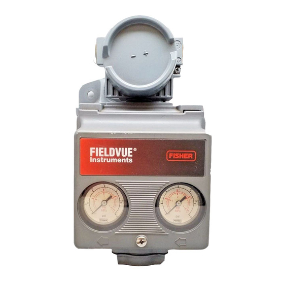
!"#$%%% &'()'*
+,-.!"/-
!)0)123 "234' #561(533'(*
751'
89)* 0:);' <(54);'* )6*123321)56= )6)1)23
*'1:< 26; >23)?(21)56= 26; @2)61'A
626>' )6B5(@21)56 B5( 19' !"#$%%% &'A
()'* ;)0)123 "234' >561(533'(*C &'' 19'
+,-.!"/- !"#$%%% &'()'* !)0)123
"234' #561(533'( ,6*1(:>1)56 D26:23 A
+5(@ $EE$= 242)32?3' B(5@ F5:( +)*9'(
('<('*'6121)4' 5( *23'* 5BB)>'= B5( 2;;)A
1)5623 )6B5(@21)56= 5( 4)*)1 5:( G'?*)1'
21 GGGC+,-.!"/-C>5@C
"
!"#$%
!"#$ %&#'( )**+#($ ,-.
/012333 4(5#($
/(?#>(
@#5<A)5(
;(?#$#-=
;(?#$#-=
B
C
?05 *+-.#/" "++ 2.%+ E>E
!
!"#$%%% &'()'*
6-'(+ 782 9:;!
1-<<&=#>),-5
9)5'A)5(
/(?#>( /($>5#*,#-=
;(?#$#-=
;(?#$#-=
2
B )=' D
,$#-#./ 1+-)2 .$* 3./#45.-#0$
12+7#8#7.-#0$" .$* 9+/.-+* :07);+$-"
<)#7=>1-.5- ()#*+
?05; @ABA
C0D+;4+5 EFFF
!"#$% &'#" ()#*+
,$"-.//.-#0$
6.#$-+$.$7+
H
I
E
J
$
Advertisement
Table of Contents


Need help?
Do you have a question about the Fieldvue DVC5010 and is the answer not in the manual?
Questions and answers
oosward161@gmail.com