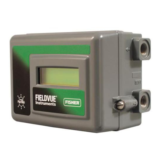
Fisher FIELDVUE DVC2000 Quick Start Manual
Digital valve controller
Hide thumbs
Also See for FIELDVUE DVC2000:
- Instruction manual (80 pages) ,
- Instruction manual supplement (28 pages) ,
- Mounting instructions (8 pages)
Table of Contents
Advertisement
Quick Start Guide
D103203X012
™
Fisher
FIELDVUE
Controller
Contents
. . . . . . . . . . . . . . . . . . . . . . . . . . . . . .
. . . . . . . . . . . . . . . . . . . . . . . . . . . . . . . . . .
. . . . . . . . . . . . . . . . . . . . . . . . . . . . . . . .
. . . . . . . . . . . . . . . . . . . . . . . . . . . . . . .
Scan or click
to access
field support
Note
This guide provides installation, connection, and basic setup and calibration information using the local operator interface.
Refer to the DVC2000 digital valve controller instruction manual (D103176X012) for detailed configuration and calibration
using the Field Communicator, maintenance and troubleshooting information, and replacement part details. This document is
available from your Emerson sales office, Local Business Partner, or Fisher.com.
www.Fisher.com
™
DVC2000 Digital Valve
. . . . . . . . . . . . . . . . . . . . . .
. . . . . . . . . . .
. . . . . . . . . . . . . . . . . . . .
2
4
4
15
18
29
31
W8861-2
DVC2000 Digital Valve Controller
July 2017
Advertisement
Table of Contents

Related Manuals for Fisher FIELDVUE DVC2000


Summary of Contents for Fisher FIELDVUE DVC2000
-
Page 1: Table Of Contents
Refer to the DVC2000 digital valve controller instruction manual (D103176X012) for detailed configuration and calibration using the Field Communicator, maintenance and troubleshooting information, and replacement part details. This document is available from your Emerson sales office, Local Business Partner, or Fisher.com. www.Fisher.com... -
Page 2: Local Interface Flow Chart
Quick Start Guide DVC2000 Digital Valve Controller July 2017 D103203X012 Local Interface Flow Chart These items are identified by an alert icon on the default screen Home Screen TRAVEL = 66.8% TRAVEL CHECK CHECK I/P SHUTDOWN CHECK 14.6 MA 0.92 BAR DEVIATION MOUNTING ACTIVATED... - Page 3 Quick Start Guide DVC2000 Digital Valve Controller D103203X012 July 2017 Only when transmitter / limit switch hardware is installed REPLACE MAIN SWITCH1 = OPEN PROTECTION FW3:1, HW1:2 " OFF BOARD SWITCH 2 = CLOSED TUNING = C QUICK SETUP COMPLETE Y + B INVERT DISPLAY 180_ Note: Hold Y + B...
-
Page 4: Using This Guide
D FM Hazardous Area Approvals - DVC2000 Digital Valve Controllers (D104225X012) D ATEX Hazardous Area Approvals - DVC2000 Digital Valve Controllers (D104226X012) D IECEx Hazardous Area Approvals - DVC2000 Digital Valve Controllers (D104227X012) Documents are available from your Emerson sales office, Local Business Partner, or Fisher.com. Installation Note The DVC2000 is not designed to correct for significant stem rotation on sliding stem actuators. - Page 5 Quick Start Guide DVC2000 Digital Valve Controller D103203X012 July 2017 D Use lock‐out procedures to be sure that the above measures stay in effect while you work on the equipment. D Check with your process or safety engineer for any additional measures that must be taken to protect against process media.
-
Page 6: Linear
Figure 1 shows the available configurations. Figure 1. Housing Variations HOUSING FOR LINEAR AND ROTARY ACTUATORS, HOUSING FOR FISHER GX ACTUATORS FISHER 657 SIZE 30i - 70i, AND 667 SIZE 30i - 76i CONNECTIONS AVAILABLE: S M20 CONDUIT AND G1/4 PNEUMATIC CONNECTIONS AVAILABLE:... -
Page 7: The Linear Magnet Arrays Are Symmetrical. Either End May Be Up
INDEX MARK D Air‐to‐open sliding‐stem (linear) actuators D Air‐to‐close sliding‐stem (linear) actuators D Air‐to‐open 667 size 30i - 76i or Fisher GX actuator D Air‐to‐close 657 size 30i - 70i or GX actuator D Rotary actuators with travel up to 90 degrees MAGNET ASSEMBLY... -
Page 8: Linear
5. Align the magnet array as follows: D For air‐to‐open actuators (e.g. Fisher 667) vertically align the magnet array so that the center line of the alignment template is lined up as close as possible with the upper extreme of the valid travel range on the feedback array. -
Page 9: Linear
Quick Start Guide DVC2000 Digital Valve Controller D103203X012 July 2017 6. Tighten the fasteners and remove the alignment template. Note Use a flat end hex key to tighten the magnet assembly fasteners to a torque of 2.37 N•m (21 in•lbf) for 4 mm screws, and 5.08 N•m (45 in•lbf) for 5 mm screws. - Page 10 9. Figure 8. Mounting to Fisher GX Actuator with Insulating Gasket and O‐Ring. Figure 9. Guidelines for Applying High Process Temperature Solutions to the Fisher GX and FIELDVUE DVC2000 -100...
- Page 11 Quick Start Guide DVC2000 Digital Valve Controller D103203X012 July 2017 If the process and ambient temperatures exceed the limits indicated by zone 2, then the DVC2000 high temperature mounting kit can not be used. If temperatures exceed zone 2, you must use an extension bonnet or bracket mounted instrument. 1.
- Page 12 Quick Start Guide DVC2000 Digital Valve Controller July 2017 D103203X012 6. Tighten the fasteners and remove the alignment template. Continue on with the appropriate step 7 below. Note Use a flat end hex key to tighten the magnet assembly fasteners to a torque of 2.37 N•m (21 in•lbf) for 4 mm screws, and 5.08 N•m (45 in•lbf) for 5 mm screws.
- Page 13 Quick Start Guide DVC2000 Digital Valve Controller D103203X012 July 2017 12. Install a vent in the port on the upper diaphragm casing. Note Refer to 667 Diaphragm Actuator Sizes 30/30i through 76/76i and 87 instruction manual (D100310X012) for 667 product information.
- Page 14 Quick Start Guide DVC2000 Digital Valve Controller July 2017 D103203X012 Quarter‐Turn (Rotary) Actuators The DVC2000 digital valve controller can be mounted to any quarter‐turn (rotary) actuator, as well as those that comply with the NAMUR guidelines. A mounting bracket and associated hardware are required. Refer to figure 13. Figure 13.
-
Page 15: Electrical And Pneumatic Connections
Condensation in the air supply should be minimized. A Fisher 67CFR filter regulator with standard 5 micrometer filter, or equivalent, may be used to filter and regulate supply air. If pressure regulation is not required, a 10 micron in‐line filter may be used. - Page 16 Quick Start Guide DVC2000 Digital Valve Controller July 2017 D103203X012 The digital valve controller is normally powered by a control system output card. The use of shielded cable will ensure proper operation in electrically noisy environments. Wire size requirements are 14 AWG maximum, 26 AWG minimum.
- Page 17 Quick Start Guide DVC2000 Digital Valve Controller D103203X012 July 2017 4. If a second switch is to be used, connect the control system input card positive wire “switch input” to the +51 terminal. Connect the control system input card negative wire “switch input” to the -52 terminal. 5.
-
Page 18: Basic Setup And Calibration
Quick Start Guide DVC2000 Digital Valve Controller July 2017 D103203X012 Basic Setup and Calibration The local operator interface is available on all DVC2000 digital valve controllers. The interface consists of a liquid crystal display, four pushbuttons, and a switch for position transmitter configuration. The DVC2000 is supplied with one of three different language packs preinstalled, depending on the firmware revision and ordering option. - Page 19 Quick Start Guide DVC2000 Digital Valve Controller D103203X012 July 2017 Basic Setup WARNING Changes to the instrument setup may cause changes in the output pressure or valve travel. Depending on the application, these changes may upset process control which may result in personal injury or property damage. When the DVC2000 digital valve controller is ordered as part of a control valve assembly, the factory mounts the digital valve controller and sets up the instrument as specified on the order.
-
Page 20: Linear
Quick Start Guide DVC2000 Digital Valve Controller July 2017 D103203X012 Quick Setup When installing the DVC2000 digital valve controller on an actuator for the first time, the quick setup procedure will calibrate and tune the instrument automatically. Table 2 lists the values that are preconfigured at the factory. Table 2. - Page 21 Quick Start Guide DVC2000 Digital Valve Controller D103203X012 July 2017 Travel Calibration WARNING During calibration the valve will move full stroke. To avoid personal injury and property damage caused by the release of pressure or process fluid, isolate the valve from the process and equalize pressure on both sides of the valve or bleed off the process fluid.
- Page 22 Quick Start Guide DVC2000 Digital Valve Controller July 2017 D103203X012 Tuning WARNING Changes to the tuning set may cause the valve/actuator assembly to stroke. To avoid personal injury and property damage caused by moving parts, keep hands, tools, and other objects away from the valve/actuator assembly. To manually tune the instrument or automatically tune the instrument without changing the calibration values, the TUNING routine is available.
- Page 23 Quick Start Guide DVC2000 Digital Valve Controller D103203X012 July 2017 Table 3. Gain Values for Preselected Turning Sets Tuning Set Proportional Gain Velocity Gain Minor Loop Feedback Gain A typical starting point for most small actuators is “C”. Using the UP (Y) and DOWN (B) arrow keys will apply the values immediately.
-
Page 24: Linear
Quick Start Guide DVC2000 Digital Valve Controller July 2017 D103203X012 The factory default characteristic is LINEAR. You can also use a QUICK OPEN, EQUAL %, or CUSTOM function. However, the custom function is initially configured linear, unless you use a HART based host to reconfigure the custom points. Custom configuration can be selected, but the curve cannot be modified with the local interface. - Page 25 Quick Start Guide DVC2000 Digital Valve Controller D103203X012 July 2017 Figure 21. XMTR Switch TRANSMITTER SWITCH FOR FAIL SIGNAL + HIGH (SHOWN) OR -LOW W8839 Switch #1 Trip Point—Defines the threshold for the limit switch wired to terminals +41 and -42 in percent of calibrated travel.
- Page 26 Quick Start Guide DVC2000 Digital Valve Controller July 2017 D103203X012 Figure 22. Position Transmitter Calibration TRAVEL = 66.8% 14.6 MA 0.92 BAR QUICK SETUP TRAVEL CALIBRATION TUNING DETAILED SETUP ANALOG INPUT CALIBRATION USE Y OR B USE Y OR B POSITION "...
- Page 27 Quick Start Guide DVC2000 Digital Valve Controller D103203X012 July 2017 The UP (Y) and DOWN (B) arrow keys will allow you to change the setpoint and therefore move the valve manually. To exit the manual mode, use the LEFT (A) arrow key to return to the choice list. Select ANALOG. Note When placing the instrument back into ANALOG, the valve will step back to the position commanded by the input current.
- Page 28 Quick Start Guide DVC2000 Digital Valve Controller July 2017 D103203X012 Once switch circuit 1 is powered properly, question marks (???) will indicate that the corresponding switch is disabled. Shutdown Activated— This screen appears if the positioner has shut down and no air is being delivered to the actuator. Therefore, the valve is at its fail‐safe position.
-
Page 29: Maintenance
Quick Start Guide DVC2000 Digital Valve Controller D103203X012 July 2017 Maintenance Replaceable components on the DVC200 include the I/P converter and the pneumatic relay. When replacing the components of the DVC2000 the maintenance should be performed in an instrument shop whenever possible. Make sure that the electrical wiring and pneumatic tubing is disconnected prior to disassembling the instrument. - Page 30 Quick Start Guide DVC2000 Digital Valve Controller July 2017 D103203X012 6. Pull the manifold assembly straight out. The interconnecting board is electrically connected to the termination board with a rigid connector. 7. Remove the interconnect board from the mounting frame. 8.
-
Page 31: Specifications
Quick Start Guide DVC2000 Digital Valve Controller D103203X012 July 2017 Specifications Available Configurations Pressure Dew Point: Class 3 or at least 10_C less than the lowest ambient temperature expected Integral mounting to 657/667 or GX actuators Sliding‐stem applications Temperature Limits Quarter‐turn rotary applications -40 to 80_C (-40 to 176_F). - Page 32 Supply and Output Pressure: 1/4 NPT internal Declaration of SEP Electrical: 1/2 NPT internal Fisher Controls International LLC declares this Materials of Construction product to be in compliance with Article 4 paragraph 3 of the PED Directive 2014/68/EU. It was designed...
- Page 33 Quick Start Guide DVC2000 Digital Valve Controller D103203X012 July 2017 Table 4. EMC Summary Results—Immunity Port Phenomenon Basic Standard Test Level Performance Criteria Electrostatic discharge 6 kV contact IEC 61000‐4‐2 (ESD) 8 kV air 80 to 1000 MHz @ 10V/m with 1 kHz AM at 80% Radiated EM field IEC 61000‐4‐3 1400 to 2000 MHz @ 3V/m with 1 kHz AM at 80%...
- Page 34 Responsibility for proper selection, use, and maintenance of any product remains solely with the purchaser and end user. Fisher, FIELDVUE, and ValveLink are marks owned by one of the companies in the Emerson Automation Solutions business unit of Emerson Electric Co.
Need help?
Do you have a question about the FIELDVUE DVC2000 and is the answer not in the manual?
Questions and answers