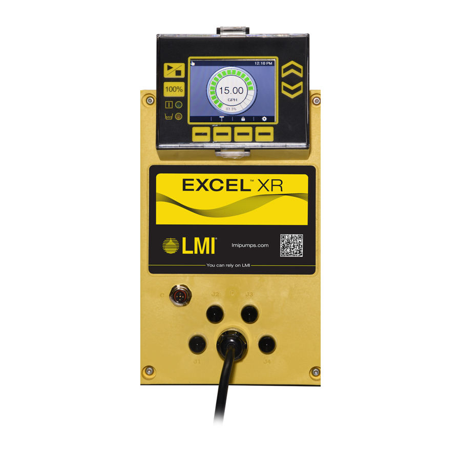
LMI Excel XR Series Installation & Operation Manual
Electronic metering pump
Hide thumbs
Also See for Excel XR Series:
- Installation & operation manual (48 pages) ,
- Instruction manual (36 pages) ,
- Manual (22 pages)

Related Manuals for LMI Excel XR Series


Summary of Contents for LMI Excel XR Series
- Page 1 Excel™ XR Series Electronic Metering Pump Installation & Operation Manual (Enhanced Control) Manual No.: 54772 Revision Rev. Date: 07/2016 Note: This manual is a supplement to 54630...
-
Page 3: Table Of Contents
Table of Contents 1.0 Precautions ..................1 2.0 Introduction..................4 3.0 Icons ....................4 4.0 Enhanced Control Operation............6 4.1 Analog Mode ....................6 4.2 Pulse Mode ..................... 7 4.3 Batch Mode ..................... 9 4.4 Cycle Timer ....................10 4.5 Timed Event Mode ..................12 4.6 Enhanced Control Inputs and Outputs ............ - Page 4 Table of Figures Figure 1: Analog Mode Home Screen ................6 Figure 2: Analog Adjust ....................6 Figure 3: Pulse Mode Home Screen ................8 Figure 4: Pulse Adjust ..................... 8 Figure 5: Batch Mode Home Screen ................9 Figure 6: Batch Adjust ....................10 Figure 7: Cycle Timer Home Screen ................
-
Page 5: Precautions
Refer to Safety Data Sheets (SDS) precautions from your solution supplier. Water Pre-Prime All LMI pumps are pre-primed with water when shipped from the factory. If your solution is not compatible with water, disassemble the Pump Head Assembly. Thoroughly dry the pump head, valves, O-rings, balls and diaphragm. - Page 6 PRECAUTIONS Back Pressure/Anti-Syphon Valve If you are pumping downhill or into low or no system pressure, a back pressure /anti-syphon device should be installed to prevent over pumping or syphoning. Contact your LMI distributor for further information. Electrical Connections WARNING: To reduce the risk of electrical shock, the metering pump must be plugged into a properly grounded grounding-type receptacle with ratings conforming to the data on the pump control panel.
- Page 7 PRECAUTIONS Flow Display The accuracy of the flow value as shown on the pump display is highly dependent on the specific application. Calibration is necessary in order to display an accurate measure of the flow. Spills CAUTION: Spills of Dangerous chemicals should be cleaned up immediately.
-
Page 8: Introduction
OPERATION 2.0 Introduction LMI's metering pumps deliver the highest level of repetitive accuracy and reliability with the capability to pump a wide range of chemicals. Our comprehensive selection of pumps means you get the right pump for the right application. Every one of our pumps is engineered to exceed expectations and is backed by a global network of highly trained field engineers and aftersales support. - Page 9 OPERATION Analogue pacing signal (loss of signal alarm) Analogue pacing signal (signal over range) Pulse input not synched Max pump volume exceeded (in pulse mode) Max flow exceed in batch mode...
-
Page 10: Enhanced Control Operation
OPERATION 4.0 Enhanced Control Operation This manual covers features supported in the enhanced control model Excel™ XR Series pumps. Enhanced control features are driven by a variety of external inputs and outputs. Please see section 5.0 Cable Wiring for information on connections, signal types, and requirements. -
Page 11: Pulse Mode
OPERATION Press Left or Right to navigate to the parameter entry boxes. Enter the desired flow rates and currents at points P1 and P2. The range of allowable values for flow rate are from zero to the maximum capacity of the pump. Input signal current can range from 0.0 to 20.0 mA. -
Page 12: Figure 3: Pulse Mode Home Screen
OPERATION Flow Rate Figure 3: Pulse Mode Home Screen # of Pulses Pulse Volume / Units Pulse Width Figure 4: Pulse Adjust FIELD ALLOWABLE VALUES Pulse Count 1 - 10000 Volume 0.1 - 10000 Units fl. oz. – GAL or mL – L (dependent on units setting) Pulse Width 4 mS –... -
Page 13: Batch Mode
OPERATION press Exit to exit without modifying the parameters. For devices with pulse widths less than 4mS, use digital input DI1. In pulse mode, when the pump receives a pulse stream, the calculated flow output value will be displayed. The Start / Stop button must be pressed or Remote Start / Stop activated for the pump to dose at the calculated flow rate. -
Page 14: Cycle Timer
OPERATION 2. Enter the values for the quantity and units of the volume of fluid to be dosed (Figure 6). NOTE: If a set of entered values results in a condition that exceeds the pump’s maximum calibrated flow, the field will be highlighted red. Increase or decrease this or one of the other parameters to clear the condition. -
Page 15: Figure 7: Cycle Timer Home Screen
OPERATION Delay Cycle Figure 7: Cycle Timer Home Screen 1. From the cycle timer home screen (Figure 7) press the Up or Down buttons to access the cycle timer adjust screen (Figure 8). 2. Enter the desired values for delay, duration and cycle times by pressing Left or Right to navigate between fields. -
Page 16: Timed Event Mode
OPERATION FIELD ALLOWABLE VALUES Delay (hr:min) 0:01 to 23:59 Duration (hr:min) 0:01 to (Cycle setting - 0:01) Cycle (hr:min) 0:01 to 23:59 Calculated Flow 0.1 to Maximum Capacity The clock starts when the Start / Stop button is pressed or a remote start signal is received. -
Page 17: Enhanced Control Inputs And Outputs
OPERATION Day of Week Event On/Off Event Parameters Figure 10: Timed Event Adjust FIELD ALLOWABLE VALUES Start Time (hr:min)AM/PM 0:01 to 12:00 AM/PM Duration (hr:min) 0:01 to (Cycle setting - 0:01) Flow Rate 0.001 to Maximum Capacity 1. Press Left and Right to navigate and the Up and Down buttons to set start time, duration and flow rate. -
Page 18: Inputs
OPERATION 4.6.1 Inputs Enhanced control model pumps have four digital and two analog configurable inputs. Digital inputs are labeled DI1 – DI4. Analog inputs are AI1 and AI2. See section 5.0 Cable Wiring, for the cable and pin assignments for each of these inputs. Each digital input can be assigned to one of five functions or <Disable>. -
Page 19: Analog Tank Level Input
OPERATION 4. Press Save and Exit Internal Mode External Mode Figure 11: Int/Ext Select With the selections shown above, the input configured per section 4.6.1.3 Configuring Enhanced Control Inputs, and cable hookups per section 5.0 Cable Wiring, a Remote Internal/External signal will toggle the pump between manual and analog modes. 4.6.1.2 Analog Tank Level Input Selecting this input overrides the digital tank level empty and tank level low inputs and combines both functions into one analog signal. -
Page 20: Outputs
OPERATION Digital Inputs 1-4 Analog Inputs 1-2 Figure 12: Configure Input In the Settings screen, navigate to configure input and press Enter . Press Left and Right to navigate between fields and the Up and Down buttons to make selections. Each input can be identified as NO (normally open) or NC (normally closed). If testing produces the opposite effect from what is desired, frequently an easy solution is to change the switch type from NO to NC or vice versa. -
Page 21: Stroke Pulse
OPERATION Output Type Function <Disable> De-activates input Stroke Pulse Indicator pulse when pump strokes Pump Running Indicates steadily while pump is dosing Pump Standby Pump Start/Stop toggled to Start, not dosing Digital Alarm Out Indicates any alarm is active Internal/External Mode Indicates if pump control is internal or external User Alarm Out Indicates any user-selected alarm is active... -
Page 22: User Alarm Out
OPERATION 4.6.2.6 User Alarm Out Similar to 4.6.2.4 Alarm Out, user alarm out becomes active when any alarm state that the user has selected occurs. 1. To configure, from the settings screen navigate to Alarm Set (Figure 13) and press Enter 2. -
Page 23: Pump Stopped
OPERATION 4.6.2.7 Pump Stopped This output becomes active when the Start / Stop button has been pressed or a Remote Start / Stop signal has been received to stop the pump and the pump status indicator is off. 4.6.2.8 Timed Event Indicates the pump is currently running in response to a pre-programmed timed event. -
Page 24: Cable Wiring
OPERATION 5.0 Cable Wiring Figure 15: Cable Wiring Diagram Connector Pin # Input/Output Type Function Input Digital Programmable Input Digital Programmable Input Digital Programmable Input Digital Programmable Power 24V DO1A Output – N.O. Contact Digital / Dry Contact Programmable DO1B Output –... -
Page 25: Figure 16: Input Diagram For Digital Inputs Di1 - Di4
OPERATION Wire Red/White Green Red/Yellow Figure 16: Input Diagram for Digital Inputs DI1 - DI4 (J1) Figure 17: Output Diagram for Digital Outputs DO1 – DO2 (J2) -
Page 26: Figure 18: Input Diagram For Analog 0-20Ma Inputs Ai1 - Ai2
OPERATION Figure 18: Input Diagram for Analog 0-20mA Inputs AI1 - AI2 (J3) Figure 19: Output Diagram for Analog 4-20mA Output AO1 (J4) -
Page 27: Troubleshooting
4. Suction tubing is curved or coiled in 4. Suction tubing must be vertical. Use tank LMI ceramic weight supplied with pump (see section 3.4 Foot Valve / Suction Tubing Installation) 5. Fittings are overtightened 5. DO NOT OVERTIGHTEN FITTINGS! - Page 28 TROUBLESHOOTING 5. Fittings are over tightened 5. DO NOT OVERTIGHTEN FITTINGS! This causes seal rings to distort and not seat properly which caused pump to leak back or lose prime 6. Air trap in suction valve tubing 6. Suction tubing should be as vertical as possible.
- Page 29 INTENTIONALLY LEFT BLANK...
- Page 30 INTENTIONALLY LEFT BLANK...
- Page 31 INTENTIONALLY LEFT BLANK...
- Page 32 LMI is a registered trademark of Milton Roy, LLC. EXCEL is a trademark of Milton Roy, LLC info@lmipumps.com www.lmipumps.com © 2016 Milton Roy, LLC...
Need help?
Do you have a question about the Excel XR Series and is the answer not in the manual?
Questions and answers