
Related Manuals for LMI ROYTRONIC EXCEL AD Series


Summary of Contents for LMI ROYTRONIC EXCEL AD Series
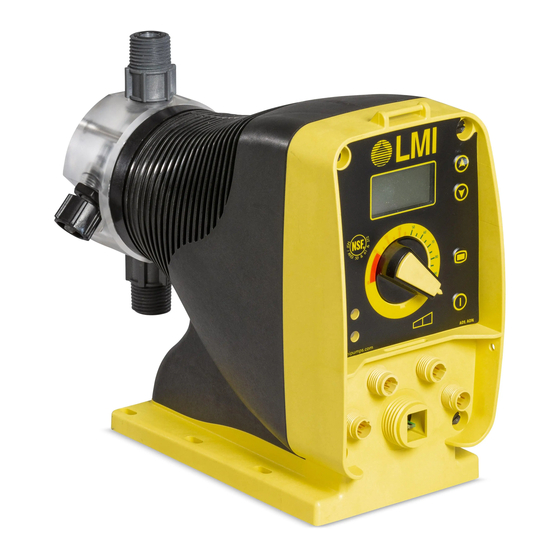
- Page 1 ROYTRONIC EXCEL™ Series AD Electronic Metering Pumps Instruction Manual Manual No : 2024 Rev. Rev. Date : 06/2019...
- Page 2 Model AD 2 5 1 - 8 3 8 S I Model Code Configuration AD2 - Dual Manual Control – Digital: Stroke frequency and length manually adjustable with digital LCD display, low level indication (remote input). Display configurable to indicate calculated pump flow. AD8 - Pulse/Analog Input w/ Dual Manual Control –...
- Page 3 Refill the pump head with the solution to be pumped before priming the pump. (This will aid in priming.) Liquid Compatibility The evaluation performed by UL was tested with water only. LMI pumps are tested to NSF ®...
- Page 4 Plumbing Always adhere to your local plumbing codes and requirements. Be sure installation does not constitute a cross connection. Check local plumbing codes for guidelines. LMI is not ® responsible for improper installations.
- Page 5 Line Depressurization To reduce the risk of chemical splash during disassembly or maintenance, all installations should be equipped with line depressurization capability. Using LMI ’s Four-Function Valve ® (4 FV) is one way to include this feature. Over Pressure Protection...
-
Page 6: Table Of Contents
TABLE OF CONTENTS SECTION 1 - INTRODUCTION . . . . . . . . . . . . . . . . . . . . . . . . . . . . . . . . . . . . . . . . . . . . . . . . . . . . . . . . . . . . . . . . . . . . . . . . . . . . . . . . . . . . . . . . . 1 1 .1 SPECIFICATIONS . - Page 7 SECTION 4 - SPARE PARTS REPLACEMENT AND ROUTINE MAINTENANCE . . . . . . . . . . . . . . . . . . . . . . . . . . . . . . . . . . . . . . . . . . . . . . 21 4 .1 DEPRESSURIZING THE DISCHARGE LINE (FOR PUMPS EQUIPPED WITH A 4-FV ONLY) .
-
Page 8: Section 1 - Introduction
® of economical and efficient metering pumps. This manual addresses the installation, maintenance and troubleshooting procedures for manually and externally controlled pumps. LMI has a worldwide ® network of stocking representatives and authorized repair centers to give you prompt and efficient service. -
Page 9: Unpacking Check List
SECTION 1 - INTRODUCTION UNPACKING CHECK LIST Your carton will contain many or all of the following items. Please notify the carrier immediately if there are any signs of damage to the pump or its parts. Foot Valve Tubing (0 to 3 Rolls) Metering Pump Ceramic Foot Injection Check... -
Page 10: Section 2 - Installation
Since the suction tubing is filled with ambient temperatures above 113°F (45°C). solution, priming is accomplished quickly and the If the pump will be exposed to direct sunlight, LMI ® chance of losing prime is reduced. A foot valve is black, UV resistant tubing should be installed. -
Page 11: Suction Lift - Wall Bracket Mount
SECTION 2 - INSTALLATION 2.2.2 Suction Lift - Wall Bracket Mount The pump may be mounted using an LMI Wall ® Mount Bracket Assembly (part no. 34643) directly above the solution tank. A pump mounted in this manner allows for easy changing of solution tanks or drums. -
Page 12: Tubing Connections
SECTION 2 - INSTALLATION 2.3 TUBING CONNECTIONS 1. Insert tubing through Coupling Nut. Tubing A. USE ONLY LMI TUBING. ALWAYS USE LMI SUPPLIED ® ® should enter the smaller end of the Coupling Nut TUBING WITH YOUR PUMP, AS THE TUBING IS SPECIFICALLY first, orienting the larger opening of the Coupling DESIGNED FOR USE WITH THE PUMP FITTINGS. -
Page 13: Four-Function Valves (4-Fv)
Contact your local LMI stocking ® distributor. The features of a 4-FV are listed below. -
Page 14: Four-Function Valves Installation
SECTION 2 - INSTALLATION 2.5 FOUR-FUNCTION VALVE INSTALLATION To install a 4-FV, the 4-FV Fitting and Coupling Nut should be assembled with the appropriate cartridges into the discharge port of the pump. Use a 13/16” or 20 mm socket to tighten fitting. Tightening to 50 inch-pounds is recommended. -
Page 15: Fastprime
SECTION 2 - INSTALLATION 2.7 AUTOPRIME™ FASTPRIME™ Pumps installed with the AUTOPRIME™ Liquid The FASTPRIME™ Head is equipped with a valve End are equipped with a valve that allows that allows for opening the head to atmospheric for constant removal of vapors and gasses pressure. -
Page 16: Foot Valve / Suction Tubing Installation
SECTION 2 - INSTALLATION 2.8 FOOT VALVE / SUCTION TUBING The ceramic weight, when installed, positions the INSTALLATION foot valve in a vertical position. The Foot Valve acts as a check valve to keep the 1. Attach the foot valve to one end of the pump primed in suction lift applications. -
Page 17: Injection Check Valve And Discharge Tubing Installation
SECTION 2 - INSTALLATION 2.9 INJECTION CHECK VALVE AND When installing the Injection Check Valve, be sure DISCHARGE TUBING INSTALLATION to position it so that the valve enters the bottom of your pipe in a vertical position. Variations left and The Injection Check Valve prevents backflow from right within 80°... -
Page 18: Section 3 -Operation
SECTION 3 - OPERATION OUTPUT ADJUSTMENT Up Button: This button increases the stroke CONTROLS speed of the pump. It will increase the stroke speed by 1 each time it is pressed. If this button is held down, it will rapidly increase the stroke speed. - Page 19 The pin functions closed for external. (and the wire color for the standard LMI ® 2. Alarm Return (Red) - Return side for the above external control cable) are as follows: pin 1 Alarm Out.
- Page 20 SECTION 3 - OPERATION 11. Low-Level Connector (3-Pin): 12. Flow Monitor / Meter Connector (4-Pin): This connector is for the connection of a Low- This connector will be used with a Milton Roy Level Sensor (49246) or a Dual-Level Sensor flow meter or the Milton Roy DIGI-PULSE™...
-
Page 21: Start-Up And Adjustment
SECTION 3 - OPERATION 3.2 START-UP AND ADJUSTMENT 3.2.2 Start-Up/Priming for Pump Supplied with 4-FV (LE-XXXSX or LE-XXXHX) 1. The pump is normally self-priming if suction lift READ THIS ENTIRE SECTION is 5 ft (1.5m) or less and the steps below are COMPLETELY BEFORE PRO-... -
Page 22: Start-Up/Priming For Autoprime™ Heads (Le-Xxxax Or Le-Xxxhx)
SECTION 3 - OPERATION 3.3 OUTPUT ADJUSTMENT 3.2.3 Start-Up/Priming for AUTOPRIME™ Heads (LE-XXXAX or LE-XXXHX) Once the pump has been primed, an appropriate READ THIS ENTIRE SECTION output adjustment MUST be made. Pump output COMPLETELY BEFORE PRO- should be calculated and adjustments made CEEDING. -
Page 23: Calibrating The Displayed Flow (Ad2, Ad8)
SECTION 3 - OPERATION 3.3.2 Calibrating the Displayed Flow (AD2, AD8) 1. Prepare a flow measuring device such as a graduated cylinder or a scale sensitive to The Roytronic Excel Pumps are equipped a gram. to display a theoretical flow rate based upon the pump’s stroke speed and stroke length. -
Page 24: Methods Of Externally Triggering Or Pacing Ad8 And Ad9 Pumps
SECTION 3 - OPERATION 3.4 METHODS OF EXTERNALLY 10. Use the Up and Down Buttons to match TRIGGERING OR PACING AD8 AND the displayed volume to the measured volume. AD9 PUMPS If using a graduated cylinder, the presence of Method of Triggering AD8 and AD9 Pumps the tubing will cause the measurement to be through External Control Connector. - Page 25 SECTION 3 - OPERATION Blue 1. Switch Closure Switch closing White triggers pump + Blue 2. NPN Transistor Base goes high − White to trigger pump + Blue 3. PNP Transistor Base goes low − White to trigger pump + Blue 4.
-
Page 26: Control Modes
SECTION 3 - OPERATION 3.4.1 Control Modes If it is necessary to change the pulse duration required to recognize a pulse from the factory 3.4.1.1 Local/Internal Mode default of 60 ms, hold both the Up Button and 1. When in local mode Roytronic Excel pumps run Down Button until a number appears followed by at the speed indicated on the LCD Display. -
Page 27: Analog Mode (For Ad8)
SECTION 3 - OPERATION 3.4.1.3.3 Analog Mode (for AD8) The pump is in Analog Mode when ‘mA’ is shown on the left-hand side of the LCD Display. Pressing the Up or Down Button will display ‘P1’ and the milliamp input that corresponds to zero strokes. -
Page 28: Section 4 - Spare Parts Replacement And Routine Maintenance
This involves replacing the LIQUIFRAM™, MAINTENANCE OR REPLACEMENT ON YOUR PUMP. cartridge valves, O-rings, and the injection check READ STEPS 1 AND 2 BELOW valve spring. LMI recommends replacing these ® BEFORE PROCEEDING. parts at least once a year; however, frequency will 1. -
Page 29: Liquifram™ (Diaphragm) Replacement
LIQUIFRAM™, cartridge clothing, gloves and face shield, immerse the valves, O-rings and the injection check valve head in water or other neutralizing solution. spring. LMI recommends replacing these parts at ® 3. Remove the four metric screws and washers least once a year;... -
Page 30: Start-Up / Priming For Autoprime™ Heads
® instructions for valve replacement. Please follow the proper Spare Parts Kit or RPM PRO PAC™ the instructions included with the replacement kit. kit number or contact your local LMI stocking ® distributor. 3. Carefully disconnect one tubing connection and fitting at a time, then remove and replace the 1. -
Page 31: Injection Check Valve Parts Replacement
® Before disassembling the check valves, note the proper Spare Parts Kit or RPM PRO PAC™ the orientation of the valve. kit number or contact your local LMI stocking ® 4. Install a new spring, seat, ball, and O-ring. distributor. -
Page 32: Fastprime™ Valve O-Ring Replacement
Metering Pump Price List for ® 5. Reinsert the FASTPRIME™ Valve assembly the proper Spare Parts Kit or RPM PRO PAC™ and retighten the Retaining Nut. Then turn kit number or contact your local LMI stocking ® the FASTPRIME™ Knob clockwise to tighten distributor. - Page 33 SECTION 4 - MAINTENANCE O-Rings O-Rings Retaining Nut 3/8" Clear Vinyl Tubing FastPrime Valve FASTPRIME Valve FASTPRIME Knob Figure 17b. FASTPRIME™ Valve O-Ring Replacement Instruction Manual...
-
Page 34: Drive Parts List
SECTION 4 - MAINTENANCE 4.7 DRIVE PARTS LIST Drive Parts List Figure 18. Bubble Number Description Bubble Number Description EPU O-Ring Stroke Dial EPU Return Spring Control Panel O-Ring EPU Shim Wire Harness Plunger O-Ring Drive Assembly Screws Retaining Ring Female Stroke Shaft Stroke Bracket Male Stroke Shaft... -
Page 35: Epu Wiring Diagram
SECTION 4 - MAINTENANCE 4.8 EPU WIRING DIAGRAM AD8 / AD9 PULSER POWER CORD EPU ASSEMBLY AD2 PULSER POWER CORD EPU ASSEMBLY Figure 19. EPU Wiring Diagram Instruction Manual... -
Page 36: Liquid End Parts
“Product” drop down to select “Liquid Handling For the latest and most accurate information on Assemblies.” your liquid end, please refer to the Liquid End 3. Select “Gallery” or ”Index” to view Liquid End Sheets available in the LMI Online Library at: ® sheets. www.lmipumps.com. - Page 37 DEPENDING ON TUBING SIZE, THE FERRULE GEOMETRY WILL BE DIFFERENT. DEPENDING ON CARTRIDGE DESIGN, AN O-RING MAY BE PRESENT AS PART OF THE ASSEMBLY Figure 21. AUTOPRIME™ Liquid End Assembly Instruction Manual...
- Page 38 OPTIONAL PIPE AND PIPE FITTINGS ARE CUSTOMER SUPPLIED DO NOT APPLY PTFE TAPE TO THIS THREAD PIPE AND PIPE FITTINGS ARE CUSTOMER SUPPLIED OPTIONAL Figure 22. Stainless Steel Liquid End Assembly Instruction Manual...
-
Page 39: Section 5 - Wiring Diagrams
SECTION 5 - WIRING DIAGRAMS 5 PIN CONNECTOR USE 5 PIN CABLE (LMI P/N 48414) PIN WIRE SIGNAL Remote On-Off White Ground-Return External Pulse Input Green-Yellow 4-20 mA Input 6 PIN CONNECTOR USE 6 PIN CABLE (LMI P/N 49035) PIN WIRE... - Page 40 SECTION 5 - WIRING DIAGRAMS INPUT WIRING DIAGRAM HALL EFFECT FLOWMETER INPUT CONNECTION REFERENCE: TANK ON INPUT CONNECTION REFERENCE: NOTE: A Cable Cord set for this application is included with an optional LMI dual switch assembly P/N 49249. ® Instruction Manual...
- Page 41 SECTION 5 - WIRING DIAGRAMS INPUT WIRING DIAGRAM TANK EMPTY INPUT CONNECTION REFERENCE: NOTE: A Cable cord set for this application is included with an optional LMI low level switch assembly ® P/N 49246 or a LMI dual level switch assembly P/N 49249.
- Page 42 SECTION 5 - WIRING DIAGRAMS INPUT WIRING DIAGRAM EXTERNAL PULSE INPUT CONNECTION REFERENCE: INTERNAL / EXTERNAL CONTROL INPUT CONNECTION REFERENCE: Instruction Manual...
- Page 43 SECTION 5 - WIRING DIAGRAMS INPUT WIRING DIAGRAM 4 - 20 MA INPUT CONNECTION REFERENCE: NOTE: 0 to 20 input impedence is dynamic and will work with supply currents needing 130 Ohm or above impedence. Instruction Manual...
- Page 44 SECTION 5 - WIRING DIAGRAMS OUTPUT WIRING DIAGRAM PULSE OUTPUT CONNECTION REFERENCE: NOTE: When using a “PULL UP” option use a 10K resistor and a 24VDC source (can be used with Pin 5 of 5 Pin CONN). 4 TO 20 MA OUTPUT CONNECTION REFERENCE: Instruction Manual...
- Page 45 SECTION 5 - WIRING DIAGRAMS OUTPUT WIRING DIAGRAM ALARM OUTPUT CONNECTION REFERENCE: NOTE: Use to switch on 24V source or less. Do not use to switch on AC line Voltage without Relay. Relay coils should be 24VDC or less with maximum Current of 35 mA. Instruction Manual...
-
Page 46: Section 6- Troubleshooting
4. Pump suction lift too high. High Viscosity Liquid Handling Assemblies require flooded suction. 5. Suction tubing is curved or coiled in 5. Suction tubing must be vertical. Use LMI ® ceramic tank. weight supplied with pump (see Section 2.7). - Page 47 ® 4-FV (see Section 2.4). Excessive 2. If pressure at injection point is less than Pump 2. Little or no pressure at injection 25 psi (1.7 Bar), an LMI ® 4-FV should be Output point. installed see Section 2.4). 3. Excessive strokes per minute.
- Page 48 is a registered trademark of Milton Roy, LLC. ® ROYTRONIC EXCEL™ is a trademark of Milton Roy, LLC. LIQUIFRAM™ is a trademark of Milton Roy, LLC. FASTPRIME™ is a trademark of Milton Roy, LLC. AUTOPRIME™ is a trademark of Milton Roy, LLC. DIGI-PULSE™...
Need help?
Do you have a question about the ROYTRONIC EXCEL AD Series and is the answer not in the manual?
Questions and answers