Table of Contents
Advertisement
Quick Links
For file reference, please record the following data:
Model No:
Serial No:
Installation Date:
Installation Location:
When ordering replacement parts for your LMI Pump, please include the complete
Model Number and Serial Number of your unit.
Instruction
Instruction
Instruction
Instruction
Instruction
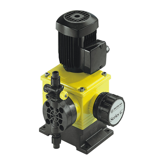
Series G, Model B
Motor-Driven Pump
Manual
Manual
Manual
Manual
Manual
8 Post Office Square
Acton, MA 01720 USA
TEL: (978) 263-9800
FAX: (978) 264-9172
http://www.Imipumps.com
Replace same of 1784 Rev. A 1/98
1784 B. 12/99
1
Advertisement
Table of Contents

Related Manuals for LMI G Series


Summary of Contents for LMI G Series
- Page 1 For file reference, please record the following data: Model No: Serial No: Installation Date: Installation Location: When ordering replacement parts for your LMI Pump, please include the complete Model Number and Serial Number of your unit. 8 Post Office Square Acton, MA 01720 USA TEL: (978) 263-9800 FAX: (978) 264-9172 http://www.Imipumps.com...
-
Page 2: Table Of Contents
Table of Contents 1.0. Description ............................... 3 1.2 Principle of Operation ..........................3 1.3 General Specifications ........................3 1.4 Product Code ............................ 4 2.0. Installation ..............................5 2.1 Unpacking ............................5 2.2 Safety precautions ..........................5 2.3 Storage ............................. 5 2.4 Handling of Pump .......................... -
Page 3: Description
It is important that the pressure in the liquid end remain above the vapor pressure of the process fluid during the suction stroke. If the fluid pressure drops below the vapor pressure, cavitation will occur, negatively impacting the performance of the pump. If you suspect the possibility of cavitation, contact an LMI Master Distributor for assistance. -
Page 4: Product Code
Product Code Series G Pumps are available in a variety of different configurations. For a breakdown of the options included in a specific pump, compare the pump model number and product code found on the pump nameplate with the model/product code breakdown shown in Figure 1. -
Page 5: Installation
Installation Unpacking Pumps are shipped f.o.b. factory or distributor warehouse and the title passes to the customer when the carrier signs for receipt of the pump. In the event that damages occur during shipment, it is the responsibility of the customer to notify the carrier immediately and to file a damage claim. -
Page 6: Mounting
To minimize viscous flow losses when handling viscous liquids, it may be necessary to use suction piping up to four times larger than the size of the suction connection on the pump. If in doubt, contact your nearest LMI Master Distibutor to determine the necessary pipe size. - Page 7 Vent Pulsation Dampener Safety Pressure Valve Gauge Back Pressure Valve Calibration Column To Injection Supply Tank Point Prime/Air Purge Valve Strainer Pulsation Dampener Metering Pump = Shut off Valve To Drain Figure 5: Typical Recommended Pump Installation Scheme Suction Piping Considerations •...
- Page 8 To prevent a blocked discharge line from causing damage to the pump, piping, or process equipment, install an LMI Safety Valve in the pump discharge line. This valve is designed and sized to handle system flow rates and pressures safely while resisting corrosion by the process liquid.
-
Page 9: Leak Detection
Leak Detection Series G, Model B pumps are equipped with a leak detection port. For ease of installation, each pump has a plastic tubing connector installed in the leak detection port (see item 448 in Figure 8). In the event of a failure of the oil seal (70 in Figure 7) or diaphragm assembly (261 in Figure 8), pump drive oil or process fluid will escape from this leakage port. -
Page 10: Maintenance
The pump can be calibrated by measuring the decrease in liquid level pumped from a calibrated vessel. This method is recommended for hazardous liquids because it eliminates operator contact with the liquid. LMI test-tube Calibration Columns are available for convenient and accurate calibration of any pump. -
Page 11: Shipping Pumps For Repair
Refer to the instructions in the “Corrective Maintenance” section. Check Valves LMI recommends that check valve balls, seats, gaskets, and O-Rings be replaced on an annual basis. If highly corrosive material (acids, slurries, etc.) is being pumped, some applications may require more frequent replacement. -
Page 12: Corrective Maintenance
Corrective Maintenance Before carrying out any servicing operation on the metering unit or pipes, disconnect electrical power from the pump, and take the necessary steps to ensure that the harmful liquid they contain cannot escape or come CAUTION into contact with personnel. Suitable protective equipment must be provided. Check that there is no pressure before proceeding with dismantling. - Page 13 Plastic Check Valves: Reassembly 1. Fit new O-Rings into position on the ball guide and seat. To assure a tight, leak free seal, new O-Rings should be used each time the check valves are disassembled. 2. Drop the ball into the curved inner chamber end of the ball guide. 3.
- Page 14 4. Position the check valve assembly onto the liquid end, trapping a gasket between the two metal surfaces. (Seat and pump head). 5. Slide the valve clamp (437) over the connection (435) and screw into the liquid end using the three screws (441,442) and their split washers (439).
- Page 15 Reassembly (Refer to Figures 7 and 8) 1. With the stroke adjusting knob at 100% and the diaphragm fully forward as in steps 1 and 5 above, screw the diaphragm assembly into the connecting rod until it reaches its natural mechanical stop. 2.
-
Page 16: Troubleshooting Guide
Troubleshooting Guide Symptoms & Remedies Pump will not operate ......• Low process liquid level in the tank. Add liquid. • Worn or dirty check valves. Clean or replace. • Blocked discharge line. Clear line. • Frozen liquid. Thaw liquid throughout pumping system. •... - Page 17 Motor and pump body hot ..... • Normal operating temperature of both motor and pump body is frequently uncomfortable to the touch. However, neither should exceed 200° F (93° C). • Power supply does not match electrical requirement of motor. Insure proper matching of power supply and motor.
-
Page 18: Parts (Figures 7 Through 14)
Parts Basic Parts 56C Motor IEC 80 Motor Check valves Refer to Figures 9-12 Figure 7: Series G Basic Parts — Side View... - Page 19 Basic Parts Figure 8: Series G Basic Parts — Top View...
- Page 20 Check Valve Parts Figure 10: B40 Metallic Check Valve Parts Figure 9: B40 Plastic Check Valve Parts Figure 11: B60 & B80 Plastic Check Valve Parts Figure 12: B60 & B80 Metallic Check Valve Parts...
- Page 21 Basic Parts Figure 13: B80 Liquid End Adapter Parts...
- Page 22 Basic Parts Check Valves Ref. to Figures 9-12 Figure 14: Double Diaphragm (Optional)
-
Page 23: Parts Lists
Parts Lists Basic Parts List (Refer to Figure 7) l a i l a i l a i l a i l a i — — — — — — — — — — — — — — e t t —... -
Page 24: Check Valve Parts List
Basic Parts List - Continued (Refer to Figures 8 & 14) Drawing Qty. Location Description Material Part Number Req. Reference 316 SS 305-0976-120 60150 Diaphragm Assembly (B40 Liquid End) Polypropylene 305-0976-110 PVDF 305-0976-130 316 SS 305-0976-320 60151 Diaphragm Assembly (B60 Liquid End) Polypropylene 305-0976-090 PVDF... - Page 25 Basic Parts List - Continued ( refer to Figures 8, 13, and 14) Single Row Bearing — 60057 Retaining Ring — 040-4010-7231 O-Ring (2-230) Buna N 040-8009-5171 Stroke Adjustment Screw — 60442 Stroke Scale — 025-3004-6062 Stroke Adjustment Screw Insert —...
- Page 26 Check Valve Parts List (refer to Figures 9 through 12) Part Number Drawing Liquid End Qty. Location Description Material PUMP Reference Liquid End Liquid End 316 SS See Note 2 029-2005-2016 003-0155-071 003-0106-071 Ball Guide Polypropylene 003-0155-070 003-0106-070 PVDF 003-0155-078 003-0106-078 316 SS 305-0876-602...
-
Page 27: 8.0 Statement Of Limited Warranty
8.0 Statement of Limited Warranty LMI TERMS AND CONDITIONS OF SALE: 1. Seller warrants that the equipment delivered by it to the Buyer is in accordance with the Seller’s published specifications and is of the kind and of the description contained in seller’s invoice. - Page 28 8 Post Office Square Acton, MA 01720 USA TEL: (978) 263-9800 FAX: (978) 264-9172 http://www.Imipumps.com © 1999 LMI Milton Roy - All Rights Reserved Liquifram is a trademark of Liquid Metronics Incorporated Printed in USA Specifications subject to change without notice.
Need help?
Do you have a question about the G Series and is the answer not in the manual?
Questions and answers