Table of Contents
Advertisement
Quick Links
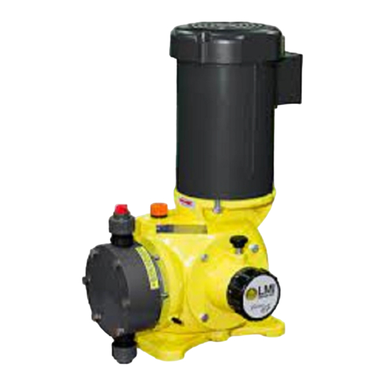
Series G Model D
METERING
PUMP
INSTALLATION,
OPERATION, AND
MAINTENANCE
MANUAL
Please record the following data for file reference
Tag Number(s): _____________________________________
Model Number: _____________________________________
Serial Number: _____________________________________
Installation Date: ____________________________________
Installation Location: ________________________________
339-0080-000
ISSUED JULY 2011
Advertisement
Table of Contents

Related Manuals for LMI G Series


Summary of Contents for LMI G Series
- Page 1 Series G Model D METERING PUMP INSTALLATION, OPERATION, AND MAINTENANCE MANUAL Please record the following data for file reference Tag Number(s): _____________________________________ Model Number: _____________________________________ Serial Number: _____________________________________ 339-0080-000 Installation Date: ____________________________________ ISSUED JULY 2011 Installation Location: ________________________________...
- Page 2 Precautions Amendment to Pump Manual For Pumps with PVC & 316SS Liquid Ends WHEN USED IN SWIMMING POOLS OR SPAS/HOT TUBS (ANSI/NSF 50) 1. Caution on Chemical Concentration: There is a potential for elevated chemical concentration during periods of no flow, for example, during backwash in the system.
-
Page 3: Table Of Contents
TABLE OF CONTENTS SECTION DESCRIPTION PAGE Series G Model D Pump Model Number and Options ................iii 1.0 DESCRIPTION ............................1 1.1 General Information ........................... 1 1.2 Principles of Operation ........................2 1.3 General Specifications ........................3 2.0 INSTALLATION ............................5 2.1 Unpacking ............................ - Page 4 SECTION DESCRIPTION PAGE 4.5 Corrective Maintenance ........................16 4.5.1 Check Valve Assemblies Replacement: Liquid Ends SD2 and SD4 - PVC, PVDF, and ............................16 4.5.2 Check Valve Replacement: Liquid End Sizes SD2 and SD4 - Polymer ......17 4.5.3 Check Valve Replacement: Liquid End Sizes SD2 and SD4 - Metallic ......17 4.5.4 Check Valve Replacement: Liquid End Sizes SD4 - Slurry ..........
- Page 5 MACROY D PUMP MODEL NUMBER AND OPTIONS Frame and Liquid End (D Frame) Liquid End Material Code Description Code Description Max 0.7 GPH / 175 PSI PVDF Max 12.0 GPH 316ss Max 50 GPH Max 115 GPH Polymer Service Slurry Applications Stroking Speed Applications Code...
- Page 6 THIS PAGE INTENTIONALLY BLANK...
-
Page 7: Description
SECTION 1 DESCRIPTION 1.1 GENERAL INFORMATION The basic pump components as illustrated in Figure 1 are: The Series G Model D is a reciprocating, chemical dos- ing pump capable of producing flows up to 115 gallons • a drive device comprising a motor (1) per hour (430 liters per hour) at pressures up to 175 psi •... -
Page 8: Principles Of Operation
Figure 2: Stroke Control Operating Principle Zero Stroke Setting Suction Phase Discharge Phase Setting to Maxmum Stroke Worm Diaphragm Worm Gear Stroke: two times the distance between (A) and (B) Eccentric Position at rear neutral point Connecting Rod Position at forward neutral point 1.2 PRINCIPLES OF OPERATION Mechanically Actuated Diaphragm Liquid End (See Figure 2) -
Page 9: General Specifications
As the diaphragm starts forward on the discharge stroke PAINT: the pressure immediately rises inside the liquid end. Power Coating When the liquid end pressure rises above the discharge line pressure, the discharge ball check is “pushed” up- ward and the process fluid in the liquid end flows into SUCTION LIFT: the discharge line. - Page 10 THIS PAGE INTENTIONALLY BLANK...
-
Page 11: Installation
SECTION 2 INSTALLATION 2.1 UNPACKING Electrical Equipment 1. Motors should be prepared in the manner prescribed Pumps are shipped f.o.b. factory or representative ware- by their manufacturer. If information is not available, house and the title passes to the customer when the dismount and store motors as indicated in step 3 be- carrier signs for receipt of the pump. -
Page 12: Mounting
Figure 3: Series G Model D Dimensional Outline 2.5 DRIP COLLECTION ING PLACE. A NOTICE SHOULD BE POSTED BY THE POWER SWITCH TO WARN THAT In the event of a failure of the diaphragm or oil seal bel- SERVICING IS BEING CARRIED OUT ON THE lows, provisions need to be made to contain the pro- EQUIPMENT. - Page 13 Figure 4: Typical Installation Injection Nozzle Tank Foot Valve (with Filter) Shut-off Valve Metering Pump Filter Process Piping Pulsation Damper Bleed Valve...
-
Page 14: Npsh Considerations
Figure 5: General Piping 2.6.1 NPSH CONSIDERATIONS Because vapor in the liquid end will cause inaccurate pump delivery, piping should be sloped up from pump Size piping to accommodate peak instantaneous flow. suction check to the supply tank to prevent formation of Because of the reciprocating motion of the pump dia- vapor pockets. -
Page 15: Discharge Piping Considerations
2.7 VALVES tive pressure applications it is important that all con- nections be absolutely drip free and vacuum tight, and Back Pressure Valves that a foot valve be installed at the bottom of the suction line (see upper left illustration of Figure 4). All metering pumps are prone to overpumping (exces- sive output) at low discharge pressures. -
Page 16: Electrical Connections
2.8 ELECTRICAL CONNECTIONS OPERATION WITH THE WRONG MOTOR RO- TATION MAY DAMAGE THE PUMP AND MO- TOR AND VOID THE WARRANTY. DO NOT FORGET TO CONNECT THE EARTH TERMINAL ON THE MOTOR TO THE EQUIP- MENT EARTH CONDUCTOR. Ensure that the electrical supply matches the pump motor nameplate characteristics. -
Page 17: Operation
SECTION 3 OPERATION 3.1 START-UP PROCEDURES AND CHECKS flowing from the priming valve. If no priming valve is in place, when the liquid end is primed, the discharge Check that the pump is secured to its support. check valves can be heard to be operating (should hear a clicking noise caused by movement of check valve If oil was previously removed for any reason, make sure balls). - Page 18 ITEM ITEM ITEM ITEM NOMENCLATURE NOMENCLATURE NOMENCLATURE NOMENCLATURE Housing Female Eccentric O-Ring Sticker Gasket Spring Pin Side Cover Bearing O-Ring Stroke Adjust Key Screw Worm Oil Drain Plug Gear Key Washer Motor Coupling Gear Retaining Ring Stroke Lock Ball Screw Connecting Rod Bearing Stroke Lock Screw...
-
Page 19: Maintenance
Assuming the pump has been calibrated as described in Section 3, the capacity can be checked by shutting As in the case of the diaphragm, LMI/Milton Roy Com- the valve from the supply vessel and opening the valve pany recommends that check valve balls, seats, gas-... -
Page 20: Spare Parts
Figure 7: Diaphragm Assemblies By Liquid End Size and Material SD4 (Plastic) SD7 and SD8 SD4 (316SS) 4.4 SPARE PARTS 4.4.1 SIZE D2 LIQUID ENDS - PVC, PVDF, POLY- MER, AND H The following spare parts should be stocked for each pump to prevent serious delays in repairs. -
Page 21: Size Sd4 Liquid Ends - Pvc, Pvdf, Polymer, H 2 So 4 , And Slurry
2 each, O-Ring: Item 419, Seat: Item 420, Ball: Item 1 each, PTFE Washer: Item 274 in Figure 12. 422, Cartridge: Item 426, Washer: Item 427 and 2 each, Cartridge Assy.: (P/N 39461) Included in Spring: Item 428 (Discharge Only) in Figure 9. Kit and Coupling Nut: Item 428 in Figure 12. -
Page 22: Size Sd7 And Sd8 - Liquid Ends - Stainless Steel
Check Valve Replacement 2 each, Seat: Item 420, Ball: Item 422 in Figure 13. General 4 each, O-Ring: Item 419 in Figure 13. Before beginning work on the valve assemblies, make Liquid End Kit for D7/D8 Polymer sure the suction and discharge shut-off valves are closed and that pressure has been bled from the pump liquid RPM 211/210, Includes: end. -
Page 23: Check Valve Replacement: Liquid End Sizes Sd2 And Sd4 - Polymer
Suction 1. Unscrew the valve body (424) from the pump head (280). 2. Remove the valve assembly: assembly includes ball DO NOT APPLY PTFE TAPE TO THE (422), seat (420), Cartridge (426), O-ring (419), and THREADS OF CHECK VALVE BODY THAT washer (427). -
Page 24: Check Valve Replacement: Liquid End Sizes Sd4 - Slurry
Disassembly 2. Unscrew the check valve assembly (425) from the pump head (280). Remove the check valves by unscrewing them from the pump head. 3. Screw the union nut part way (one or two turns) onto the end of the ball guide (424) that has the seat in it. Be Reassembly sure the union nut is on loosely. -
Page 25: Check Valve Replacement: Liquid End Size Sd7 And Sd8 - Polymer
(C) REVERSE PUMPING ACTION (FROM 2. Remove the valve assembly: assembly includes two DISCHARGE LINE INTO SUCTION LINE) O-rings (419), seat (420), ball (422), poppet (426), spring (423) and check valve body (424). 1. Drop the ball (422) into the curved inner chamber end of the body (424). -
Page 26: Diaphragm And Oil Seal Bellows Replacement
4.6.1 DIAPHRAGM REPLACEMENT: LIQUID END Reassembly SIZE SD2 (SEE FIGURES 6, 9, AND 10) 1. Loosen the head screws (Item 290 in Figure 9) and remove the diaphragm head (Item 280 in Figure 9). Mark THE ORDER OF ASSEMBLY AND ORIENTA- the suction and discharge ports on the diaphragm head TION OF THE SUCTION AND DISCHARGE prior to removal. -
Page 27: Oil Seal Bellows Replacement
5. Make sure that stainless steel support nut (270) is Note: Steps 13 and 14 are applicable to Liquid clean and free of corrosion. When cleaning the support End Size SD7 and SD8 (See Figure 6). nut, take care not to scratch the smooth angled surface 15. -
Page 28: Restarting The Pump
4.8 RESTARTING THE PUMP 7. Remove the diaphragm support ring (Item 230 in Fig- ure 12) from the spacer (225). 1. Reconnect the pump to the piping system. 8. Drain the oil out of the pump drive by removing the 2. -
Page 29: Parts List
SECTION 5 PARTS LIST GENERAL 1. This section gives information regarding replaceable components. ILLUSTRATED PARTS LIST 1. Figure and Item Number Column (a) The item numbers shown in the detailed parts list correspond to the item numbers appearing on the exploded view illustration. To find an unknown part number, locate the part on the illustration and note the item number. - Page 30 Figure 8. Drive Assembly...
-
Page 31: Parts List For Drive
5.1 PARTS LIST FOR DRIVE FIGURE QUANTITY ITEM PART DESCRIPTION NUMBER PUMP NUMBER NUMBER Drive Housing Assembly, D2, 43 SPM, (NE56C) SD-40-01-NE56C Drive Housing Assembly, D2, 43 SPM, (IEC71) SD-40-01-IEC71 Drive Housing Assembly, D2, 86 SPM, (NE56C) SD-20-01-NE56C Drive Housing Assembly, D2, 86 SPM, (IEC71) SD-20-01-IEC71 Drive Housing Assembly, D2, 173 SPM, (NE56C) SD-10-01-NE56C... - Page 32 Figure 9: D2 Plastic Liquid End...
-
Page 33: Parts List For D2 Plastic Liquid End Pvc, Pvdf, H 2 So
5.2 PARTS LIST FOR D2 PLASTIC LIQUID END PVC, PVDF, H , AND POLYMER-NPT / PVC, PVDF - TUBING. Model: Reference Code: Model: Reference Code: D2_ _ 8P _ _ _ _ (PVC NPT) D2_ _ NP _ _ _ _ NPT) D2_ _ 8T _ _ _ _ (PVC TUBE) -
Page 34: Parts List For Sd2 Metallic Liquid End Stainless Steel-Npt
Figure 10: SD2 Metallic Liquid End ASSEMBLY ASSEMBLY 5.3 PARTS LIST FOR SD2 METALLIC LIQUID END STAINLESS STEEL-NPT Model: SD2 _ _ 7P FIGURE ITEM PART QUANTITY REFERENCE DESCRIPTION NUMBER NUMBER NUMBER PUMP CODE Diaphragm/Oil Seal Bellows 60048 Oil Seal Clamp Ring 60043 Spacer 61035... -
Page 35: Parts List For Sd4 Metallic Liquid End Stainless Steel-Npt
Figure 11: SD4 Metallic Liquid End ASSEMBLY ASSEMBLY 5.4 PARTS LIST FOR SD4 METALLIC LIQUID END STAINLESS STEEL-NPT Model: SD4 _ _ 7P FIGURE ITEM PART QUANTITY REFERENCE DESCRIPTION NUMBER NUMBER NUMBER PUMP CODE Oil Seal Clamp Ring 60043 Spacer 61035 Pan Head Screw, M6 X 20 70054... - Page 36 5.4 PARTS LIST FOR D4 METALLIC LIQUID END STAINLESS STEEL-NPT Model: D4 _ _ 7P _ _ _ _ A (316SS) FIGURE ITEM PART QUANTITY REFERENCE DESCRIPTION NUMBER NUMBER NUMBER PUMP CODE 61059 Pan Head Screw, #10-24 X 3/4 Check Valve Assembly CV202294 Liquid End Kit, 316SS RPM 104...
-
Page 37: Pvdf, And H 2 So 4 - Tubing
5.5 PARTS LIST FOR D4 PLASTIC LIQUID END PVC, PVDF, H , SLURRY, AND POLYMER-NPT / PVC, PVDF, AND , H -TUBING. Model: Reference Code: Model: Reference Code: D4_ _ 8P _ _ _ _ (PVC NPT) D4_ _ NP _ _ _ _ NPT) D4_ _ 8T _ _ _ _ (PVC TUBE) -
Page 38: So -Npt
5.5 PARTS LIST FOR D4 PLASTIC LIQUID END PVC, PVDF, H , SLURRY, AND POLYMER-NPT / PVC, PVDF, AND , H -TUBING. Model: Reference Code: Model: Reference Code: D4_ _ 8P _ _ _ _ (PVC NPT) D4_ _ NP _ _ _ _ NPT) D4_ _ 8T _ _ _ _ (PVC TUBE) - Page 39 THIS PAGE INTENTIONALLY BLANK...
- Page 40 Figure 13: D7 & D8 Plastic Liquid End...
- Page 41 5.6 PARTS LIST FOR D7 AND D8 PLASTIC LIQUID END PVC-NPT/TUBING, PVDF-NPT, POLYMER-NPT, SLURRY-NPT, & H -NPT. Model: Reference Code: Model: Reference Code: D7/D8_ _ 8P _ _ _ _ A (PVC NPT) D7/D8_ _ NP _ _ _ _ D (H NPT) D7/D8_ _ 2P _ _ _ _...
- Page 42 5.6 PARTS LIST FOR D7 AND D8 PLASTIC LIQUID END PVC-NPT/TUBING, PVDF-NPT, POLYMER-NPT, SLURRY-NPT, & H -NPT. Model: Reference Code: Model: Reference Code: D7/D8_ _ 8P _ _ _ _ A (PVC NPT) D7/D8_ _ NP _ _ _ _ D (H NPT) D7/D8_ _ 2P _ _ _ _...
- Page 43 Figure 14: D7 & D8 316SS Liquid End...
-
Page 44: Parts List For Sd7 And Sd8 316Ss-Npt Liquid End
5.7 PARTS LIST FOR SD7 AND SD8 316SS-NPT LIQUID END Model: SD6 _ _ 7P or SD8 _ _ 7P FIG. ITEM QTY. REF. DESCRIPTION PART NO. PART NO. PUMP CODE Adapter 61155 61155 Socket Head Set Screw, M8 X 20 4350016075N 4350016075N Oil Seal Bellows... -
Page 45: Troubleshooting
SECTION 6 TROUBLESHOOTING SYMPTOMS POSSIBLE CAUSE REMEDY 1. Pump motor won't operate. a) Low process liquid level in the a) Add liquid. tank. b) Worn or dirty check valves. b) Clean or replace. c) Blocked discharge line. c) Clear line. d) Frozen liquid. - Page 46 SYMPTOMS POSSIBLE CAUSE REMEDY 3. Erratic pump delivery. a) Leaky suction piping. a) Repair piping. b) Leaky safety valve. b) Repair or replace valve. c) Insufficient suction head. c) Raise suction tank level and/or install foot valve in suction line. d) Liquid near boiling.
- Page 47 THIS PAGE INTENTIONALLY BLANK...
- Page 48 201 Ivyland Road • Ivyland, PA 18974 USA • (215) 293-0401 • Fax: (215) 293-0445• www.lmipumps.com E-mail: info@lmipumps.com...
Need help?
Do you have a question about the G Series and is the answer not in the manual?
Questions and answers