
Related Manuals for Beckman Coulter LS 13 320


Summary of Contents for Beckman Coulter LS 13 320
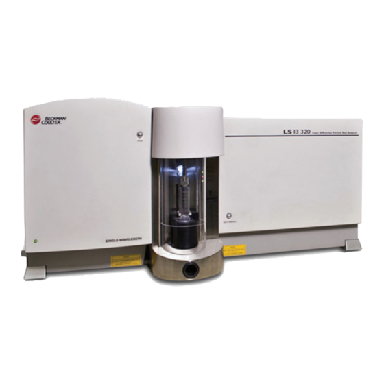
- Page 1 User’s Manual LS 13 320 Laser Diffraction Particle Size Analyzer PN B05577AC July 2017 Beckman Coulter, Inc. 250 S. Kraemer Blvd. Brea, CA 92821 U.S.A.
- Page 2 PN B05577AC (July 2017) Copyright © 2017 Beckman Coulter, Inc. All rights reserved. Beckman Coulter, the stylized logo, and the Beckman Coulter product and service marks mentioned herein are trademarks or registered trademarks of Beckman Coulter, Inc. in the United States and other countries.
-
Page 3: Revision History
Revision History This document applies to the latest software listed and higher versions. When a subsequent software version affects the information in this document, a new issue will be released to the Beckman Coulter Web site. For labeling updates, go to www.beckmancoulter.com... - Page 4 Revision History PN B05577AC...
-
Page 5: Safety Notice
Safety Notice Read all product manuals and consult with Beckman Coulter-trained personnel before attempting to operate instrument. Do not attempt to perform any procedure before carefully reading all instructions. Always follow product labeling and manufacturer’s recommendations. If in doubt as to how to proceed in any situation, contact your Beckman Coulter Representative. - Page 6 Information CAUTION Read all product manuals and consult with Beckman Coulter-trained personnel before attempting to operate instrument. Do not attempt to perform any procedure before carefully reading all instructions. Always follow product labeling and manufacturer’s recommendations. If in doubt as to how to proceed in any situation, contact your Beckman Coulter Representative.
- Page 7 Laser Safety The LS 13 320 contains a 5 mW diode laser. The instrument therefore may pose certain hazards associated with low-power lasers if misused. You should be aware of these possible hazards as described in the next paragraph. Additionally, misuse of diluents for sample dispersion can also create hazardous situations.
- Page 8 Safety Labels Radiation Hazards In the design and manufacture of the BECKMAN COULTER LS 13 320, Beckman Coulter Inc., Particle Characterization Group, has complied with the requirements governing the use and application of a laser as stipulated in regulatory documents issued by the U.S. Department of Health and Human Services and the Center for Devices and Radiological Health (CDRH).
- Page 9 Safety Notice Safety Labels or on those covers that, when removed, might expose laser radiation. Refer to the figure titled Warning labels - Instrument Front Cover And Laser Cover for the warning labels and their locations. Warning labels - Instrument Front Cover And Laser Cover Certification Label (Instrument Back Cover) PN B05577AC...
- Page 10 • Do not use any diluents that are not compatible with the specific wetted surface of the sample module. Consult Beckman Coulter or its local representative before using any chemicals not listed in this manual. • Proper handling procedures for diluents and reagents used in particle analysis should be adhered to at all times.
- Page 11 • Take care disconnecting diluent lines. Open-ended tubing may allow liquid to spill out of the vessel. • Never place containers of liquids on top of the LS 13 320. Repair of instruments damaged or affected by spilled liquids will not be covered by any warranty.
- Page 12 Safety Notice Scope of Manual PN B05577AC...
-
Page 13: Table Of Contents
Contents Revision History, iii Safety Notice, v LS 13 320 Introduction, xxiii CHAPTER 1: Theory, 1-1 Theoretical Background, 1-1 Light Scattering, 1-1 Theory, 1-2 3.1.2 Fraunhofer Theory, 1-2 Polarization Intensity Differential Scattering (PIDS), 1-3 3.1.4 Particle Non-Sphericity & Light Scattering, 1-4... - Page 14 Measure Background, 2-12 Measure Loading, 2-12 Running a Control, 2-13 Running a Sample, 2-18 Reference Background, 2-19 CHAPTER 3: LS 13 320 Software, 3-1 File Menu Options, 3-2 Window Menu Options, 3-11 Run Menu Options, 3-12 Preference Options, 3-17 Printed...
- Page 15 Contents Additional Security Features, 4-8 Data Mirroring, 4-8 File Attributes, 4-8 Starting Security-Enabled Software, 4-9 CHAPTER 5: Data File Menus, 5-1 RunFile Menu, 5-1 Open for Overlay, 5-1 Save, 5-3 Export, 5-3 Info, 5-6 Get File History, 5-6 Edit Menu, 5-7 View Menu, 5-9 Graphs, 5-9...
- Page 16 Contents Software, 6-24 Menu, 6-24 File Menu, 6-25 Edit Menu, 6-26 8.2.3.1 APS Run Menu, 6-26 Auto-Prep Station Settings, 6-27 8.2.3.2 APS Select Menu, 6-29 8.2.4 APS Troubleshooting, 6-30 Micro Liquid Module, 6-30 Description, 6-31 Loading the MLM, 6-32 Software, 6-32 Control Menu, 6-32 Stirrer...
- Page 17 ULM, 6-78 Cleaning Fluids, 6-78 Cleaning the Cell, 6-79 Replacing the Diffraction Cell Window, 6-81 Troubleshooting, 6-85 Specifications, 6-85 APPENDIX A: LS 13 320 Specifications, A-1 Specifications, A-1 APPENDIX B: Sample Handling, B-1 Material Handling, B-1 Liquid Sampling, B-1 Solid...
- Page 18 Background, D-4 Part 2 - Using the Reference Background, D-8 APPENDIX E: Maintenance, E-1 Cleaning Procedures, E-1 Cleaning Fluids, E-1 Cleaning the Lens, E-1 Fourier Lenses, E-2 Projection Lens, E-3 Beckman Coulter, Inc. Customer End User License Agreement Related Documents xviii...
- Page 19 Optical Model Dialog Screen, 2-19 2.18 Run Cycle Options Dialog, 2-21 2.19 Reference Background File Selection, 2-22 LS 13 320 Software, 3-1 User Privileges Dialog: No Security, 3-43 User Privileges Dialog: Low Security, 3-45 User Privileges Dialog: Medium Security, 3-46...
- Page 20 Illustrations Drain Valve Knob, 6-3 Figure 4 Line Locations and Connections, 6-4 Inlet and Drain Lines, 6-5 Sample Cell, 6-5 PIDS Windows Thumbscrews, 6-16 Diffraction and PIDS Windows, 6-16 6.10 Diffraction Window, 6-18 6.11 Pencil Reflections Test, 6-19 6.12 Auto-Prep Station with Aqueous Liquid Module, 6-22 6.13 Connecting the...
- Page 21 Illustrations 6.42 Sheath Flow Filter, 6-64 6.43 Miscibility Guide, 6-78 6.44 Cell Cover Thumbscrews, 6-80 6.45 Cleaning Inside the Cell Windows, 6-80 6.46 Diffraction Cell Windows, 6-81 6.47 Difraction Cell Window Levers, 6-82 6.48 ULM Cell Window Nylon Screw Removal, 6-82 6.49 Pencil, 6-83 Figure 1.
- Page 22 Tables Tables Table 4.1 LS 13 320 Power Requirements, 2-2 Initial Dialog Box After Software Launch, 2-6 Controls Used With Specific Sample Modules, 2-13 Mean Diameters, C-6 xxii...
-
Page 23: Introduction
1, measures the size distribution of particles suspended either in a liquid or in dry powder form by using the principles of light scattering. The LS 13 320 particle size analyzer provides reliable and reproducible results for researchers, quality control laboratories, product and process control departments, or anyone with the need to measure particle size distributions. - Page 24 Figure 2 PIDS Detectors The LS 13 320 is designed to be fully compliant with the ISO standard covering particle sizing by the laser scattering method (ISO 13320-1 Particle size analysis - Laser scattering methods - Part 1: General principles).
- Page 25 LS 13 320 Introduction Determining PSD An important component of making this measurement in an LS 13 320 instrument is the Fourier lens (Figure 3). A Fourier lens serves two functions: it focuses the incident beam so it will not interfere with the scattered light, and it also transforms the angularly-scattered light into a function of location on the detection plane.
- Page 26 The LS 13 320 Optical Bench Overview The LS 13 320 optical system is comprised of a source of illumination, a sample chamber in which the sample interacts with the illuminating beam, a Fourier lens system used to focus the scattered light, and an array of photodetectors that record the scattered light intensity patterns.
- Page 27 Open Light Source The LS 13 320 uses a 5 mW laser diode with a wavelength of 750 nm (or 780 nm) as the main illumination source. It also has a secondary tungsten-halogen light source for the PIDS system. The...
- Page 28 The delivery system may include certain features such as a circulation pump, an ultrasonic probe, or stirring bars to help better disperse and circulate the particles. The LS 13 320 operates with sample cells designed for particles suspended in liquids or in dry powder form. These modules are: •...
- Page 29 MS Windows Version Software The Microsoft Windows-based LS 13 320 control program provides both hardware control and data management. Among other functions, the program allows you to: • Display, print, store, and export data. • Customize (user interface) on-screen and printed reports.
- Page 30 LS 13 320 Introduction System Components PN B05577AC...
-
Page 31: Theory
The technique is fast and flexible, and also provides precise and easily adaptable measurements. The LS 13 320 series of instruments analyze the patterns of scattered light produced to provide precise and reproducible particle size distributions. Theoretical Background... -
Page 32: Mie Theory
Theory Theoretical Background In characterizing particle size using light scattering, a sample concentration is optimized to a proper range. This range allows enough scatter intensity for the measurement to be completed with a desired signal-to-noise ratio, but not to the point of saturating the detecting system. The sample concentration is also optimized for minimal particle-particle interaction and minimal multiple scattering so that the measurement is performed based on elastic single particle scattering. -
Page 33: Polarization Intensity Differential Scattering (Pids)
Combining the polarization effects of light scattering with the wavelength dependence at high angles, Beckman Coulter can extend the lower size limit to as low as 17 nm, almost reaching the theoretical limit. This approach is the Polarization Intensity Differential Scattering (PIDS) technique.. -
Page 34: 3.1.4 Particle Non-Sphericity & Light Scattering
Theory Polarization Intensity Differential Scattering (PIDS) visualized in Figure 1.2. Thus, if a detector is facing the direction of oscillation it will receive no scattering from single dipoles. When the light beam is polarized in either the vertical or the horizontal direction, the detected scattering intensity I and I at a given angle will be different. -
Page 35: Pids Sizing
” PIDS Sizing As mentioned above, with its patented PIDS assembly the LS 13 320 can provide information about particles within the range of 0.017 microns. Particles in this range offer limited information in diffraction patterns, so the PIDS technology is required to accurately measure these small particles. -
Page 36: Description
Theory PIDS Sizing Description The PIDS assembly provides the primary size information for particles in the 0.017 µm to 0.4 µm range. It also enhances the resolution of the particle size distributions up to 0.8 µm. This additional measurement is needed because it is very difficult to distinguish particles of different sizes by diffraction patterns alone when the particles are smaller than 0.4 µm in diameter. -
Page 37: Installation
Beckman Coulter Service Representative is responsible for unpacking, installing, and setting the instrument for you. Each LS 13 320 is tested before shipping. International symbols and special handling instructions are printed on the shipping cartons to inform the carrier of the precautions and care applicable to electronic instruments. -
Page 38: Temperature And Humidity Requirements
The Aqueous Liquid Module requires clean, bubble-free liquid as suspension fluid. Regular tap water that is filtered and degassed can be used. Beckman Coulter recommends that you use a 0.2 µm or smaller pre-filter. PN B05577AC... -
Page 39: Drain For Aqueous Liquid Module
Vacuum for Tornado Dry Powder System The Dry Powder System requires a vacuum source (optionally supplied by Beckman Coulter) for operation. If you choose to supply one, you will need a unit capable of sustaining rates up to 420 L/minute at 740 to 750 torr (15 cfm at 5 to 10 inches of water below atmospheric pressure). -
Page 40: Software Installation
The software installation begins automatically when you insert the CD into the computer's CD drive. Just follow the prompts to complete the installation. Configuring Software Parameters To configure the connection parameters for your LS 13 320 and PC: From the LS 13 320 software program select Security... -
Page 41: Instrument Verification
Beckman Coulter personnel. Getting Started The PC software has been designed to control all the operations of the LS 13 320. Once the instrument and its corresponding module have been set up and the software installed, click on the program icon to launch the program. -
Page 42: Security Level Options
Installation Getting Started Table 2.2 Initial Dialog Box After Software Launch Non-Compliant Software Compliant Software Figure 2.4 Security Level Options The status screen shown in Figure 2.4 allows you to select the security level you wish to use. For more on security levels refer to Security Options. Once a security level has been selected, the dialog screen shown in Figure 2.4 will not be displayed again. -
Page 43: Setting Up For Compliance
Installation Getting Started Figure 2.5 User Set-up Flowchart Setting Up For Compliance If you selected the security option as described in Security Options, a dialog box appears requiring you to enter a user name and password. If the security option was not selected it can be selected at this time. - Page 44 Installation Getting Started From the Main Menus select Security The security level option dialog box is displayed. 21 CFR Part 11 to display the following screen. Click on the to display the Add a User Account dialog box. The Add a User... Full Name Login , and...
- Page 45 Installation Getting Started After completing the required information and selecting , another user may be added at this point. After all users have been added, select Cancel and the following dialog screen will be displayed. You will be prompted to choose a new password. PN B05577AC...
-
Page 46: Selecting A Module
(Figure 2.6). . If there is no module connected to the LS 13 320 or there is a Use Optical Module (COM 1) problem with communication between the computer and the LS 13 320 bench, an error message will... -
Page 47: Selecting An Optical Module
Figure 2.7 Message When An Optical Module Is Not Found IMPORTANT If this occurs, ensure that an optical module is connected to the LS 13 320 bench. Make sure that the module is docking properly; otherwise contact your Beckman Coulter Service Representative. -
Page 48: Making Measurements
In the LS 13 320, the laser beam is aligned within 1-2 microns of the center of the detector array on the horizontal and vertical axes. -
Page 49: Running A Control
The above steps are recommended when analyzing a sample in order to obtain consistent and accurate results. The selection of the controls (provided by Beckman Coulter) to be used will depend on the sample module being used and are listed in Table 2.3. -
Page 50: Run Menu
Installation Making Measurements and select the check box (see Figure 2.10) if your sample contains New Sample Include PIDS particles below 0.4 µm (ULM and ALM only). Figure 2.10 Run Menu 2-14 PN B05577AC... -
Page 51: Measuring Offsets Screen
Installation Making Measurements . A sequence of steps will automatically follow after selecting as indicated Start Start below. a. Measuring offsets Figure 2.11 Measuring Offsets Screen b. Alignment Figure 2.12 Auto Align Screen PN B05577AC 2-15... -
Page 52: Measuring Offsets Screen
Installation Making Measurements c. Background measurement Figure 2.13 Measuring Offsets Screen d. Measure loading Figure 2.14 Measuring Obscuration (Loading) Screen Once the correct obscuration is obtained, click on the button to continue to Start Analysis the next step. 2-16 PN B05577AC... -
Page 53: Sample Info Dialog
Installation Making Measurements e. Sample information Figure 2.15 Sample Info Dialog Run information Figure 2.16 Run Settings Dialog PN B05577AC 2-17... -
Page 54: Running A Sample
Installation Making Measurements Complete the sample and run information dialog boxes with the pertinent information. The above procedures can be greatly simplified by using either the Standard Operating Method and/or Standard Operating Procedure features. For more on these procedures see the sample module section. -
Page 55: Reference Background
Installation Making Measurements From this point on the sequence of steps is the same as described in the previous section Running a Control. Figure 2.17 Optical Model Dialog Screen As with controls, the sample analysis steps can be simplified through the use of Standard Operating Methods and Procedures (see your specific sample module manual for more information). - Page 56 ZXBYYYY.$ls, where: X = L for the ALM U for the ULM M for the MLM P for the Tornado DPS Y = the last four digits of the optical LS 13 320 bench serial number 2-20 PN B05577AC...
-
Page 57: Run Cycle Options Dialog
Installation Making Measurements Figure 2.18 Run Cycle Options Dialog PN B05577AC 2-21... -
Page 58: Reference Background File Selection
Installation Making Measurements Figure 2.19 Reference Background File Selection 2-22 PN B05577AC... -
Page 59: Chapter 3
CHAPTER 3 LS 13 320 Software Figure 3.1 LS 13 320 Software PN B05577AC... -
Page 60: File Menu Options
LS 13 320, it must have an extension that matches what is shown in the Files of type: field. -
Page 61: Ls 13 320 Software,
LS 13 320 Software File Menu Options To open a file: or click on the icon. File > Open Open Select the file you want to open and click Open PN B05577AC... - Page 62 LS 13 320 Software File Menu Options The results screen is displayed along with a box that displays the statistics as shown below. If the statistics box is not displayed, you may access it by selecting Analyze > Show Statistics on Graph...
- Page 63 LS 13 320 Software File Menu Options Overlay... Overlay is analogous to Open, but allows you to open a total of 30 files and display them as an overlay in one graph. Saving an overlay as a .ovr file only saves a list of the names of the files in the overlay.
- Page 64 LS 13 320 Software File Menu Options Average... command allows you to create a single file produced by averaging the data from up to Average 150 files on a channel-by-channel basis. Some information (especially header information not common to all files) is not included in the composite file, but the individual runfiles themselves are not altered by the function.
- Page 65 LS 13 320 Software File Menu Options Create Size Trends... command allows you to view and print sequences or groups of analyses in a Create Size Trend single graph. It provides a graph/listing of a chosen sample statistics across sample files. For...
- Page 66 Using file names with a 3-character extension beginning with the symbol '$' is recommended when saving imported data. Files that have an extension beginning with "$" will be automatically recognized by the LS 13 320 program. PN B05577AC...
- Page 67 LS 13 320 Software File Menu Options In the dialog box (see next figure) select the first and last lines that include the data of interest followed by the channel sizes and data. PN B05577AC...
- Page 68 LS 13 320 Software File Menu Options Open Overlay List... Opens a saved overlay file (.ovr). Average From List... Opens files with the extension .avg. Change Folder... The Change Folder command can be used to locate data files stored elsewhere on your computer.
-
Page 69: Window Menu Options
LS 13 320 Software Window Menu Options Window Menu Options Copy Window... command creates a copy of the current active window and pastes it into the Copy Window Windows buffer, where it can then be pasted into other applications. Cascade... -
Page 70: Run Menu Options
LS 13 320 Software Run Menu Options Run Menu Options IMPORTANT The Run menu shown above will become active once the optical module is connected to the Run Cycle... menu allows you to set all the parameters necessary to perform an analysis on a Run Cycle sample. - Page 71 LS 13 320 Software Run Menu Options Running a Control for more information on the options under the menu. Run Cycle Run Cycle Options... This option allows the user to set up parameters for various parts... the offset, alignment, and background measurements that will be used under the menu described above.
- Page 72 LS 13 320 Software Run Menu Options Loading of the sample can be controlled either by obscuration, sample weight, or sample volume. Any one of these options is selected by checking the corresponding check box under Sample Loading Options Create SOP... Load SOP...
- Page 73 LS 13 320 Software Run Menu Options Refer to your specific Sample Module section in this manual for further instructions. Make Optical Model... Making optical models is necessary to obtain the correct size distribution on your particular sample. For more on optical models refer to APPENDIX C, Optical Models.
- Page 74 LS 13 320 Software Run Menu Options File Name Generation... The file name generation dialog is used to determine the format of new file names. Existing file names cannot be edited using this option. Selecting different options from the “File Name Generation” dialog box will allow you to give your analysis a unique identification with up to 271 characters plus an extension.
-
Page 75: Preference Options
LS 13 320 Software Preference Options Preference Options Preference files define the settings for data presentation, the appearance of the program window, the format for reports, etc. At any time, you may change any of the settings in the dialog boxes accessed by commands in the Preferences menu. - Page 76 LS 13 320 Software Preference Options analysis using user-selectable channel boundaries • Interpolation: trend data graphical and tabular format options • Size Trend Graph: trend data in a tabular format • Trend Listing: presents size data (tabular or graphical) using sieve format by mesh size or mesh number •...
- Page 77 LS 13 320 Software Preference Options Size Listings... tab allows you to customize tabular data presentations by selecting Size Listing Preferences specific listing information and designating column sequence for quick output to the printer. Make your selections by clicking the desired option boxes; click again to deselect. Up to seven categories of information may be included in tabular data output.
- Page 78 LS 13 320 Software Preference Options Size Interpolation option software utilizes a reduced number of user-specified size classes to Size Interpolation categorize sample data. Use the Interpolation dialog box to enter up to 150 interpolation points. In the group box labeled Interpolation Type, select the distribution % type to size that you want printed.
- Page 79 LS 13 320 Software Preference Options Statistics option is used to define the distribution and statistic type used. It is also useful in Statistics defining which percentiles and statistics appear on the size statistics report and when selecting option from the individual run file menu.
- Page 80 LS 13 320 Software Preference Options 3-22 PN B05577AC...
- Page 81 LS 13 320 Software Preference Options Sieve... dialog offers the option of presetting the size data in a format that allows comparison of Sieve data obtained with sieves. The sieve option allows you to show a , as well as .
- Page 82 LS 13 320 Software Preference Options “Sieve Listings” will print up to seven distribution listings including Mesh Size Trend... allows you to view and print sequences or groups of analyses in a single graph. Size Trend Analysis A statistical quantity, such as the mean, can be plotted versus time of analysis, date of analysis, or several other choices.
- Page 83 LS 13 320 Software Preference Options Result Options Result Options will allow you to select the units of measure in which the data will be reported, i.e. mm3 for volume. The Default View option under this menu lets you choose the display format that will appear at the end of an analysis.
- Page 84 LS 13 320 Software Preference Options Averaging and Trend Displays the dialog box, which may be used to select the type of measure Averaging and Size Trend to use, distribution type, and trend limits type. It allows file names printed with their full path, and an option to add data from other averaged or trend files.
- Page 85 LS 13 320 Software Preference Options Numeric formatting options are also included in the dialog. Data Export Page Setup tab provides all the options necessary to set up how the report will be printed. By Page Setup checking the radio button for...
- Page 86 LS 13 320 Software Preference Options 3-28 PN B05577AC...
- Page 87 LS 13 320 Software Preference Options Graph Options Under this tab you will find all the option to set up the way graphs will be printed in a report. PN B05577AC 3-29...
-
Page 88: Preference Files
LS 13 320 Software Preference Options Fonts & Colors This option allows you to set different font types and sizes as well as colors for headings, listings, graphs and statistics for display and for the printed reports. Preference Files... brings up a dialog box with the names of stored preference files. Selecting one of... - Page 89 LS 13 320 Software Preference Options Saving a preference file: Select Preferences > Preference Files Select and enter a name for the preference file under the field. Save Preference As… File Name Make sure the file is saved under the correct folder. If you want this preference to be your default preference, use the option.
-
Page 90: Security Options
LS 13 320 Software Security Options Security Options The Security options allow the software to be configured for 21 CFR part 11 (for the compliant version of software only) compliance. This option also permits the operation of the software with some degree of security to be able to keep the integrity of the data being acquired by the instrument and stored in electronic form. - Page 91 LS 13 320 Software Security Options This diagram summarizes the steps when setting up a security level: PN B05577AC 3-33...
-
Page 92: Security Setup
LS 13 320 Software Security Setup Security Setup The Security Set-up box is accessible when the program is first started after installation. Once a security level is set-up it cannot be changed to a different level. Even though the level cannot be changed, different settings are accessible through the User Privileges options which is accessible only by the administrator. -
Page 93: 5.5.2 Types Of Users
LS 13 320 Software Security Setup After completing the required information and selecting , you will be prompted to add another user. Select if another user is to be added. Repeat step 3. If not select Cancel After an account has been set up, the user will be prompted to change his/her password. - Page 94 LS 13 320 Software Security Setup passwords. The figure below shows the menus accessible by the administrator when logged-in in Administrator Mode To access this screen: Select Security Select Enter Administrator Mode If prompted, enter your Log-in ID Password Selecting displays.
- Page 95 LS 13 320 Software Security Setup as password expiry and dialog inactivity, and has the required password lengths. Select the options in the dialog box and click NOTE The dialog has a button marked 21 CFR 11 (for the compliant version of software only). When activated this ensures all options are set so that the settings meet with the rules as applicable to 21 CFR part 11.
-
Page 96: Add A User Account
LS 13 320 Software Security Setup is also accessed from the User Privileges screen or Administrator drop down Audit Trail Settings menus. Audit trail settings allows you to select the events to monitor. These events relate to SOMs, SOPs as well as analysis runs, electronic signatures and preference files. For more information on audit trailing see Audit Trail. -
Page 97: Edit A User Account
LS 13 320 Software Security Setup Edit a User Account Under this option, a current user's account can be edited. Note that only the Type of user, Log-in Name, Full Name, and ID can be edited. View User Account Info This option keeps track of any changes done to a user's account as well as the number of log-ins done by the user. -
Page 98: Supervisor
LS 13 320 Software Security Setup Supervisor Supervisor is the second highest ranking user after Administrator. To access this mode you must follow the log-in steps as long as there is an account set up for a supervisor. Both the administrator and supervisor have access to the menu items shown in the figure above. -
Page 99: Customize Run Menus
LS 13 320 Software Security Setup Customize Run Menus Choices made in this dialog determine the menus that will NOT be available when setting up RunFile , and , and . Clicking on any one of these options will deactivate it. -
Page 100: Recent Files And Directories
LS 13 320 Software No Security Recent Files and Directories This dialog box controls the number of files and folders shown in the main File menu. It is accessed by the Administrator from the Administrator menu. No Security By selecting , there is no need for log-in ID's or passwords. -
Page 101: Low Security
LS 13 320 Software Low Security Figure 3.2 User Privileges Dialog: No Security Low Security Low security requires an administrator to set up accounts for other users. A full name, log-in name and password are required as well as the type of user. - Page 102 LS 13 320 Software Low Security The Add a User Account dialog box is displayed. Fill in the dialog boxes with the proper information and choose the type of user from the drop down list box. After filling in the dialog boxes with the proper information and selecting , you will be prompted to add a user account.
-
Page 103: Medium Security
LS 13 320 Software Medium Security Figure 3.3 User Privileges Dialog: Low Security NOTE Under this security level only the Administrator is required to log in. Medium Security As with low security, requires the Administrator to set up accounts for other users. -
Page 104: High Security
LS 13 320 Software High Security Figure 3.4 User Privileges Dialog: Medium Security Under this security level all users need to log-in, but only the administrator and supervisor are required to provide a password. The option to add an electronic signature is left open only for the Administrator and Supervisor. -
Page 105: User Privileges Dialog: High Security
LS 13 320 Software High Security Figure 3.5 User Privileges Dialog: High Security PN B05577AC 3-47... -
Page 106: Logging Out
LS 13 320 Software Logging Out Logging Out As shown under Administrator and User Names and Passwords, a user is logged out after a certain period of time set by the Administrator. The user can also log out by selecting Log-Out from user dialog box. -
Page 107: Chapter 4: Regulatory Compliance - 21 Cfr Part
LS 13 320 software. File History is enabled for any file created by the LS 13 320 software in 21 CFR Security mode. Under these conditions, all changes made to a file are automatically recorded. These changes consist of computer-generated, time-stamped audit trails to independently record the data and time of operator entries and actions that create, modify, or delete electronic records. - Page 108 Regulatory Compliance - 21 CFR Part 11 Electronic Record Control - 21 CFR Part 11 be ensured that, audit trail documentation is retained for a period at least as long as that required to maintain records. To access the File History information: On the menu, click .
-
Page 109: Audit Trail
Close Audit Trail In addition to the auditing associated with the electronic file itself the LS 13 320 software offers two additional levels of auditing, as follows: 1. A general system trails all records and stores information at a system level; for example, who logged in when, when users were added to the system, and so on. -
Page 110: Electronic Signatures
Non-biometric signatures are those that are computer generated and employ at least two distinct identification components such as an identification code and password. It is this form of electronic signature that is supported by the LS 13 320 software. PN B05577AC... -
Page 111: Generating Electronic Signatures
Add a User Account dialog screen. The identification code or user name of each LS 13 320 user must be unique. No two users on the same LS 13 320 system can have the same user name. It is also required that users, supply a password to access the LS 13 320 software, thus satisfying the requirement of employing at least two distinct identification components, identification code and password. - Page 112 Regulatory Compliance - 21 CFR Part 11 Electronic Record Control - 21 CFR Part 11 The following screen is displayed. Provide your password and select a meaning for the electronic signature from the pull down options or type a new meaning. The Electronic Signature Meanings can be created from the User Privileges dialog box.
-
Page 113: Applying Electronic Signatures
The LS 13 320 software uses the application of the user name and password to authenticate the user making and saving the changes, in conjunction with file history and audit trailing, to independently record the date and time of operator entries and actions that create, modify, or delete electronic records. -
Page 114: Additional Security Features
Regulatory Compliance - 21 CFR Part 11 Additional Security Features Additional Security Features The LS 13 320 software offers two important additional levels of security, that while not specifically called for by the regulations, make defining and implementing system policies easier. Data Mirroring The administrator has the option to securely store files in a separate location and in addition to that specified by a user. -
Page 115: Starting Security-Enabled Software
Starting Security-Enabled Software After all settings for 21 CFR Part 11 security have been configured, every time the LS 13 320 software is started, the user is prompted to enter a user name and password. The software will automatically configure according to the privileges granted to the user by the administrator. - Page 116 Regulatory Compliance - 21 CFR Part 11 Starting Security-Enabled Software 4-10 PN B05577AC...
-
Page 117: Data File Menus
Open for Overlay The LS 13 320 software enables you to view more than one data file on the same graph. This is useful when you want to compare data from different files. To open new data files for overlay. - Page 118 Data File Menus RunFile Menu Select the file you wish to overlay with the current opened file. Open PN B05577AC...
-
Page 119: Save
Data File Menus RunFile Menu Unlike the Overlay command, which allows you to select multiple files at once, the Open for Overlay command allows you to open one file at a time. You can overlay up to 30 files. Save Modified (edited) files must be saved in order for any changes to take effect. -
Page 120: Export Data Dialog Box
Data File Menus RunFile Menu Figure 5.1 Export Data Dialog Box Click the appropriate export option check boxes. By default, files export to Microsoft Excel. You can select a different location in the Export To section. When finished, click . The Preferences dialog box displays. Export PN B05577AC... -
Page 121: Preferences Data Dialog Box Exporting Data
Data File Menus RunFile Menu Figure 5.2 Preferences Data Dialog Box Exporting Data Select additional settings as necessary. After selecting Settings the following dialog box is displayed. PN B05577AC... -
Page 122: Get Info
Data File Menus RunFile Menu Get Info Information about the run parameters and sample info are contained in this dialog. Get File History The file history is linked to the Audit Trail. This screen records any changes that have been made to a file. -
Page 123: Edit Menu
A setup with security selection for the Edit menu would have “Add Electronic Signature” displayed. Copy Window This command will place the information displayed in the LS 13 320 window onto the clipboard. Edit Sample Info Information about the sample can be edited through this option. Under all levels of security, except No Security, any changes made during the editing process will be recorded in the File History. - Page 124 Data File Menus Edit Menu Edit Size Results Edit size results allows you to actually add and/or delete data values from your size distribution. Under No Security any user has access to this option. For Low and Medium Security the operator and reviewer are not allowed to edit the size data.
-
Page 125: View Menu
Data File Menus View Menu View Menu The View menu allows you to choose the way the data is presented on your computer screen. This format can be printed as it appears on the screen using the RunFile, Print command. The data can be displayed in graphical form, by listings, or by showing a set of interpolation points. -
Page 126: Display Values On One Channel
Data File Menus View Menu The graph options are selected from the Graph menu as shown in the next figure. Once a graph is displayed there are several operations that can be executed. These are covered in the next sections. Display Values on One Channel Point the arrow to a channel and press the left button of the mouse to display a cursor and the channel's value. -
Page 127: Listing
Data File Menus View Menu Listing The listing options are shown in the following figure. The options selected will be displayed in tabular form with the first column being the first option selected. PN B05577AC 5-11... -
Page 128: Analyze Menu
Analyze Menu Analyze Menu Statistics See APPENDIX C, Optical Models Statistics, for definitions of statistics used in the LS 13 320 program. To view the statistics for the active run file: On the Analyze menu, click Statistics. Statistics information displays. -
Page 129: Compare To Standard
Data File Menus Analyze Menu To view the statistics for only part of the size distribution, add cursors around the desired portion of the distribution and repeat steps to 3. Compare to Standard Compare to Standard enables you to compare a file against a standard. Standard files can be an actual instrument control sample or a sample that is designated to be a standard control for other similar samples. - Page 130 Only the results from the last optical model used for analysis are stored with the run file. - This factor, also known as the shape factor, helps correlate results obtained from the e-factor LS 13 320 to those obtained by other methods, such as the Coulter Principle, SEM, etc. 5-14 PN B05577AC...
-
Page 131: Sample Modules
Universal Liquid Module Aqueous Liquid Module The Aqueous Liquid Module (ALM) is intended for use with the LS 13 320 Optical Bench. It is capable of suspending samples in the size range of 0.017 µm to 2000 µm. Figure 6.1 Aqueous Liquid Module (ALM) with Sample Cell The ALM presents the entire sample to the instrument by re-circulating the sample. -
Page 132: Alm Description
Sample Modules Aqueous Liquid Module ALM Description System Description The ALM system consists of: • A sample vessel containing the suspension fluid and dispersed sample particles. • A sample cell. • A sonicator that aids in the dispersion of the sample. •... -
Page 133: Software,
Sample Modules Aqueous Liquid Module Figure 6.3 Indicators – opens the inlet valve. Pressing this button will open the inlet and turn the LED ON to • Fill indicate the vessel is being filled. – indicates that the pump is ON. •... -
Page 134: Connecting The Alm
Sample Modules Aqueous Liquid Module Connecting the ALM Recirculation Lines The module is connected to the sample cell by two tubes (“lines”). Refer to Figure 6.5. Line 1 carries fluid from the module to the sample cell, line 2 returns the fluid to the module, making it a closed- loop system. -
Page 135: Loading The Sample Cell Into The Optical Bench
Loading the Sample Cell Into the Optical Bench Figure 6.7 Sample Cell Open the LS 13 320 door to load the sample cell by undocking the auto-docking tray. Press the button on the instrument and the sliding door moves to the left. When it is open, press OPEN button to extend the tray toward the user. -
Page 136: Software
When these pins have engaged into the slots on the back of the Sample Cell, tip the Sample Cell up to its vertical position. The Sample Cell should now be resting on the auto-dock tray. Press the button and the Sample Cell will be drawn into the LS 13 320. EJECT MODULE CAUTION Do not place fingers inside bench as the sample cell docks into bench. -
Page 137: 8.1.3.1 Control Menu
Sample Modules Aqueous Liquid Module 8.1.3.1 Control Menu system can be operated through a Aqueous Liquid Module series of manual controls accessed through software commands. These controls offer flexibility when there is a need to operate the system manually. To access these control commands: and select the function you want to activate. -
Page 138: Standard Operating Methods (Som)
Sample Modules Aqueous Liquid Module Pump Speed This option opens a dialog box that allows you to set the speed of the pump. Click on the arrows or drag the indicator to increase or decrease the speed. Pump On – Pump Off Selecting one of these options turns the pump ON or OFF. - Page 139 Sample Modules Aqueous Liquid Module Select . A sequence of screens will guide you through the SOM creation. Create an SOM Step 1 prompts you to input a description of both the sample and the SOM being created for this particular sample.
- Page 140 Sample Modules Aqueous Liquid Module Step 3 allows you to set Run Cycle options such as offsets, alignment and background. The button will take you to the Run Cycle Options dialog box, where the measurement Cycle Options times of the offsets, background, and alignment are set. Sonication is also set within this screen. 6-10 PN B05577AC...
- Page 141 Sample Modules Aqueous Liquid Module In Step 4 the run length is chosen. For analyses that require collection of PIDS data, a run length of at least 90 seconds is recommended. For analyses without PIDS, 60 seconds is the recommended time for the analysis, though analyses may be as short as 10 seconds. The optical model can be selected during this step.
-
Page 142: 8.1.3.3 Loading An Som
Sample Modules Aqueous Liquid Module Step 5 provides the user with a summary of the options selected in the previous steps. The SOM is saved during this step. IMPORTANT SOM files, by default, are saved under the SOP folder, but they can be saved to the folder of your choice as well. -
Page 143: Standard Operating Procedures (Sop)
Sample Modules Aqueous Liquid Module 8.1.3.4 Standard Operating Procedures (SOP) Creating an SOP Standard Operating Procedures (SOPs) are the last step in setting all the parameters necessary to fully define restricted operation of the instrument. To create an SOP: Select Create an SOP From the Create an SOP dialog box, select an SOM and Preference file. -
Page 144: Suspension Fluids
The ALM requires clean, bubble-free liquid for its suspension fluid. Regular tap water that is filtered and degassed can be used. Beckman Coulter recommends that you use a 0.2 µm, or smaller, pre- filter. Only use suspension fluids in the ALM that have flash points greater than 43.3°C (110°F) and meet the requirements listed below. -
Page 145: Cleaning The Alm
Cleaning Fluids Beckman Coulter recommends cleaning solution supplied with the module for cleaning the inner surfaces of the ALM sample system. Beckman Coulter recommends lens cleaning paper for cleaning the lenses and sample cell windows. Cleaning the Cell Clean the inner surfaces of the sample system (pump, hoses and within the sample cells) whenever they become coated. - Page 146 Sample Modules Aqueous Liquid Module After removing the cover you will have access to the inside of the cell. This will allow you to insert a swab with an extension (provided with your accessory kit) to clean the inside of the cell windows.
-
Page 147: Replacing The Diffraction Cell Window
Sample Modules Aqueous Liquid Module Replacing the Diffraction Cell Window Equipment Needed • lens tissues • lens cleaning solution • window sealing tool Procedure Use this procedure to replace a diffraction sample cell window that is scratched or damaged. To replace a diffraction sample cell window: Drain liquid from module. - Page 148 Sample Modules Aqueous Liquid Module Figure 6.10 Diffraction Window 1. Difraction Cell Window 4. Nylon Screws 2. O-ring 5. Sample Cell 3. Retaining Ring 6. Supply Hose Cup your hand over the loose retaining ring and tilt the sample cell stand until the retaining ring falls into your hand.
- Page 149 Sample Modules Aqueous Liquid Module Figure 6.11 Pencil Reflections Test 1. O-ring 3. Light-Colored Reflection 2. Coated Side 4. Dark-Colored Reflection a. Take the eraser end of a pencil and hold it close to the window, near its edge. Note the two reflections, dark and light colored, of the pencil.
- Page 150 Sample Modules Aqueous Liquid Module Remove the tool and check if the O-ring is completely seated down and around the window. Clean the retaining ring, then gently place it on top of the window. Replace the two new nylon screws that hold the retaining ring. Clean the outer surface of the diffraction window as described in step 10.
-
Page 151: Alm Troubleshooting
15.4 kg (34.0 lb) Auto-Prep Station The Auto-Prep Station (APS) is intended to be used with the LS 13 320 optical bench and the Aqueous Liquid Module (ALM). It is capable of adding dispersant as well as sonicating a total of thirty samples. -
Page 152: Aps Description
Sample Modules Auto-Prep Station Figure 6.12 Auto-Prep Station with Aqueous Liquid Module The APS adds the entire amount of sample to the ALM vessel by rinsing the sample tube into the ALM vessel with water for a preset, user-selectable time. APS Description The APS consists of: •... - Page 153 Sample Modules Auto-Prep Station Figure 6.13 Connecting the APS 1. Inlet 3. To APS 2. Drain from ALM 4. To ALM Electrical and Communications The electrical and communications connections are made through two separate cables that connect from the APS to the right side of the LS bench, as shown in the figure above, and from the APS to the computer.
-
Page 154: Software
Sample Modules Software Software This section covers the software commands used to operate the Auto-Prep Station as well as how to use SOM wizards to set the APS for consistent results. Run Menu The APS is set for operation through a series of options found under the Run menu. Using these options provides flexibility in the way the APS is set up to perform analyses. -
Page 155: File Menu
Sample Modules Software The following section covers each menu of the Run the Auto-Prep Station dialog screen. File Menu – allows you to load slots that have been previously saved in a file in the same • Load All Slots order in which they were saved. -
Page 156: Edit Menu
Sample Modules Software Edit Menu • Copy All – copies information from one slot into all other slots. This is done by: — Select > Select All Slots — Edit > Copy All • Copy Sample IDs – copies the sample ID from one completed slot into all other slots. •... -
Page 157: Auto-Prep Station Settings
Sample Modules Software Auto-Prep Station Settings option helps you select the way in which the sample tubes will be set Auto-Prep Station Settings up for analysis. Three options are provided and each option has a different set up. – selecting this radial button sets all slots to use the same SOM, which is •... - Page 158 Sample Modules Software • By bar code Each tube provided with the Auto-Prep Station comes with a bar code for easy identification when setting samples for analysis. This selection provides other options to help optimize your analysis. Clicking on the Edit List button displays the following dialog box: This dialog is employed to create a list of bar codes that will be used to read the sample tube.
-
Page 159: 8.2.3.2 Aps Select Menu
Sample Modules Software Bar code type selection is done through the following screen. In order for any of these bar codes to work properly, the sample tube must have the selected code. The following are short descriptions of each of the code types. Note that the default type is Code 128. -
Page 160: 8.2.4 Aps Troubleshooting
• Check bar code label for looseness. Micro Liquid Module The LS 13 320 Micro Liquid Module (MLM) measures size distributions of particles suspended in liquids from 0.4 microns to 2000 microns. It provides reliable results for researchers, quality control laboratories, product or process control departments, or anyone needing to measure particle size distributions. -
Page 161: Mlm Description
Sample Modules Micro Liquid Module Figure 6.15 Micro Liquid Module The MLM measures the entire sample in the instrument by circulating the sample with a stir bar. The amount of sample needed depends on its size and concentration. Prior sample preparation is often needed to achieve proper dispersion (see APPENDIX B, Sample Handling for more information... -
Page 162: Loading The Mlm
Loading the MLM To install the MLM: Open the LS 13 320 door to load the sample cell by undocking the auto-docking tray. Press the button on the instrument and the sliding door moves to the left. When it is open, press OPEN button to extend the tray toward the user. -
Page 163: Stirrer Speed
Sample Modules Micro Liquid Module Figure 6.17 Figure 1 Control Menu Stirrer Speed Figure 6.18 Figure 2 Stirrer Speed This options opens a dialog box that allows you to adjust the speed of the stirrer. Click on the arrows or drag the indicator to increase or decrease the speed. The stirrer keeps the sample suspended without creating bubbles. - Page 164 Sample Modules Micro Liquid Module Step 1 (Figure 6.19) prompts you to input a description of both your sample and the SOM you're creating for this particular sample. Figure 6.19 Figure 3 Step 1 of SOM development to select or edit the suspension fluid to be used (figure 4). This screen is a Select Fluid database of common fluids plus any other fluids added by the operator.
- Page 165 Sample Modules Micro Liquid Module Figure 6.21 Figure 5 Edit Fluid List Dialog In Step 2 (Figure 6.22) information about the sample as well as the (file name format) under file name are entered. Figure 6.22 Step 2 of SOM Development In Step 3 (figure 7) offsets, alignment and background are selected.
- Page 166 Sample Modules Micro Liquid Module Figure 6.23 Figure 7 Step 3 of SOM Development Figure 6.24 Figure 8 Run Cycle Options Dialog 6-36 PN B05577AC...
- Page 167 Sample Modules Micro Liquid Module In Step 4 (figure 9) the run length is set. Sixty seconds is the recommended time for an analysis, though analyses may be as short as 10 seconds. The Stirrer Speed is also adjusted in this dialog screen.
-
Page 168: Loading An Som
Sample Modules Micro Liquid Module IMPORTANT SOM files, by default, are saved under the SOP folder, but they can be saved to the folder of your choice as well. Figure 6.26 SOM Summary Under high security (21 CFR Part 11, for compliant version of software only), SOMs can only be saved by the Administrator. - Page 169 Sample Modules Micro Liquid Module Figure 6.27 SOM List Dialog PN B05577AC 6-39...
-
Page 170: Standard Operating Procedures (Sop)
Sample Modules Micro Liquid Module When an SOM is loaded, the status panel will show information about the loaded SOM and the Start Cycle button will change to Start SOM. Clicking on this button will start an analysis using all the settings unique to that SOM. -
Page 171: Loading An Sop
Sample Modules Micro Liquid Module Select . By default the SOP file will be saved in the SOP folder. Save Figure 6.28 Create an SOP Dialog Loading an SOP To load an SOP: Select . SOPs can also be loaded from the status panel by clicking on the Load an SOP Load SOP button. -
Page 172: Suspension Fluids
Sample Modules Micro Liquid Module Figure 6.29 Figure 13 SOP List Dialog Suspension Fluids The materials used in the construction of the MLM that come in contact with the suspension fluid ® ® are Teflon , 316 stainless steel, glass, and Kal-rez Only use suspension fluids that have flash points greater than 10.0°C (50°F) and meet the requirements listed below. - Page 173 Sample Modules Micro Liquid Module Listed below are acceptable suspension fluids for the MLM. If your application requires a fluid not listed here, check with your local Beckman Coulter representative for chemical compatibility. Butanol Butanone Carbon Tetrachloride Chloroform Ethanol Ethylene Glycol...
-
Page 174: Mlm System Preparation
Sample Modules Micro Liquid Module Figure 6.30 Miscibility Guide MLM System Preparation Placing the Cell on the Sample Stand Open the door to the optical bench. If the module has been docked, undock it. Place the sample cell on the sample stand with the locator pin fitting into the locator notch on the sample stand as shown in figure 14. -
Page 175: Filling Micro Liquid Module With Diluent
Sample Modules Micro Liquid Module Figure 6.31 Locator Notch 1. Cell 2. Locator Pin 3. Locator Notch Filling Micro Liquid Module with Diluent Open the door to the optical bench. If the sample cell is placed on the stand, remove it. Remove the cap. -
Page 176: Adding Sample
Sample Modules Micro Liquid Module To remove air bubbles after the sample cell has been filled, tilt the cell to the side to allow trapped air to escape. Tilt it the opposite direction and repeat this procedure. Alternatively, place the cell on the sample stand and turn the stirring motor on at a low speed. With high viscosity fluids, you may have to turn off the motor periodically to let the bubbles rise. -
Page 177: Cleaning The Mlm
Sample Modules Micro Liquid Module Cleaning the MLM IMPORTANT Always remove the Micro Liquid Cell from the sample stand to add fluid or sample in order to prevent spills on the Micro Liquid Sample Stand or inside the optical module. If you follow this advice, only the Micro Liquid Cell will require occasional cleaning. - Page 178 Sample Modules Micro Liquid Module Figure 6.33 Sample Cell Components 1. Sample Entry Funnel 5. Stirring Bar 2. Cell Body 6. Cap 3. Locator Pin 7. Window 4. O-Ring 8. Cup It is not necessary to take the cell apart every time there is a need for cleaning. Adding a small amount of cleaning solution and scrubbing with the swab supplied can also clean the inside of the cell.
-
Page 179: Mlm Troubleshooting
Tornado Dry Powder System The Tornado Dry Powder System is intended for use with the LS 13 320 Optical Bench. It is capable of feeding and measuring dry powder samples in the size range 0.4 µm to 2000 µm. The... -
Page 180: Tornado Description
Sample Modules Tornado Dry Powder System Tornado Description The Tornado DPS system consists of: • The Tornado DPS module • A vacuum source • A vacuum hose that connects the Tornado DPS to the vacuum • Sample tubes The Tornado DPS provides automatic feed rate (obscuration) control. The set point for the obscuration is user selectable between 4% and 8%. -
Page 181: Docking The Tornado Dps
If the Power LED does not turn ON, it means the Tornado did not properly dock into the LS 13 320. Gently push the Tornado both at the top and bottom into the LS 13 320 and it should then properly dock. -
Page 182: 8.4.3.1 Control Menu
Sample Modules Tornado Dry Powder System 8.4.3.1 Control Menu The Tornado DPS system can be operated through a series of manual controls accessed through the software. and select the function you want to activate from the menu shown in the figure below. Control - Runs a cycle that runs the cleaning •... -
Page 183: Standard Operating Methods (Som)
Sample Modules Tornado Dry Powder System pressure reading. If the LED light is flashing red, indicating the vacuum is high, adjust the Upper Error Limit to be greater than the vacuum pressure reading. 8.4.3.2 Standard Operating Methods (SOM) The Standard Operating Methods (SOMs) are used in part to assure consistency in the way analyses are performed. - Page 184 Sample Modules Tornado Dry Powder System Step 2 information about the sample as well as the (file name format) under the file name is entered. Step 3 options such as offsets, alignment and background are set during this step. Run Cycle button will take you to the dialog box in which the Run Cycle Options...
- Page 185 Sample Modules Tornado Dry Powder System In Step 4 the obscuration value (%) at which the analysis will be performed is selected. For the Tornado DPS this value should be between 4% and 8%. The ISO 13320 standard suggests an obscuration value of 5% (ISO 13320-1 Particle size analysis –...
-
Page 186: 8.4.3.3 Loading An Som
Sample Modules Tornado Dry Powder System Step 5 summarizes the options selected in the previous steps. The SOM is saved during this step. IMPORTANT SOM files, by default, are saved under the SOP folder, but they can be saved to any other folder. -
Page 187: Standard Operating Procedures (Sop)
Sample Modules Tornado Dry Powder System 8.4.3.4 Standard Operating Procedures (SOP) The Standard Operating Procedures (SOPs) bring together the SOMs and the preference files, thus setting all the parameters necessary to fully control the operation of the instrument, as well as data presentation. -
Page 188: Loading An Sop
Sample Modules Tornado Dry Powder System Loading an SOP To load an SOP: Select Load an SOP. SOPs can also be loaded from the status panel by clicking on the Load SOP button. Select the desired SOP file from the SOP subfolder or the subfolder where the file was last saved. Cleaning the Tornado DPS It is important for all glass surfaces in your sample system to be clean, as dusty or coated optical surfaces can cause erroneous results. -
Page 189: Cleaning The Cell Windows
Sample Modules Tornado Dry Powder System Cleaning the Cell Windows To clean the windows the sample cell must be removed from the module housing. Loosen the screws that hold the bracket in place. Lift the bracket to disengage the pins from the pin slots. - Page 190 Sample Modules Tornado Dry Powder System Figure 6.37 Sample Cell Latches 1. Sample Cell Latches Remove the sample cell. Clean the inner and outer surfaces of the sample cell windows (refer to Figure 6.38) whenever they become coated. To clean the cell windows: Remove the set of screws holding the window you wish to clean.
-
Page 191: Cleaning The Sample Tubing
Sample Modules Tornado Dry Powder System Figure 6.38 Sample Cell Windows 1. Screws 2. Sample Cell Windows Fold three to four lens tissues in half. Apply lens cleaner onto the creased area of the folded lens tissue. Place the lens tissues on the window surface, holding the tissue in place with two fingers. Slowly, wipe the window. - Page 192 Sample Modules Tornado Dry Powder System Remove the module cover by undoing the two latches found in the back of the module (Figure 6.39). Figure 6.39 Cover Latches 1. Cover Latches Remove the wall impact plate by removing the four screws. Refer to Figure 6.40.
-
Page 193: Cleaning The Sheath Flow Filter
Sample Modules Tornado Dry Powder System Use the brush provided in the Tornado DPS accessory kit to clean the suction and sheath flow tubes in the direction shown by the arrows in Figure 6.41. Use the same brush to clean the tube that runs perpendicular to the suction tube and runs towards the sheath flow tube. -
Page 194: Tornado Dps Troubleshooting
Sample Modules Tornado Dry Powder System Figure 6.42 Sheath Flow Filter 1. Sheath Flow Filter 2. Wall Impact Plate Remove the filter (Figure 6.42) and clean with soap and water. Allow it to dry before re- installing. The filter can also be cleaned by applying vacuum to it. Tornado DPS Troubleshooting The LEDs on the Tornado DPS will aid you in troubleshooting the module. - Page 195 Sample Modules Tornado Dry Powder System Problem Possible Cause/Solution Low vacuum pressure • Sheath flow filter missing. Install filter. • Leaks. Tighten windows screws. • Sheath flow tube plugged. Clean tube. • Vacuum bag full or filter clogged. Replace vacuum bag and/or filter. High vacuum pressure •...
-
Page 196: Tornado Dps Specifications
Pressure: 740 to 750 torr (15 cfm at 5 to 10 inches of H2O below atmospheric pressure) Universal Liquid Module The Universal Liquid Module (ULM) is intended for use with the LS 13 320 Optical Bench. It is capable of suspending samples in the size range of 0.017 µm to 2000 µm. -
Page 197: Ulm Description
(provided with the module). Loading the ULM Open the LS 13 320 door to load the ULM by undocking the auto-docking tray. Press the OPEN button on the instrument and the sliding door moves to the left. When it is open, press the EJECT button to extend the tray toward the user. -
Page 198: Ulm Software
When these pins have engaged into the slots on the back of the ULM, tip the module up to its vertical position. The ULM should now be resting on the auto-dock tray. Press the button and the MLM will be drawn into the LS 13 320. EJECT MODULE CAUTION Do not place fingers inside bench as automatic sliding door closes. -
Page 199: Sop),
Sample Modules Universal Liquid Module Fill This option opens the inlet valve to fill the vessel with the diluent. The drain valve, if open, will be closed. Make sure the fill hose is completely submerged in the diluent. Rinse Selecting this option will start an automatic rinse cycle. The order of operations is Open Drain, Close Drain, Fill, and Pump On. -
Page 200: Standard Operating Methods (Som)
Sample Modules Universal Liquid Module Sonicate You may sonicate your sample before an analysis by selecting this option. The following dialog box is displayed with options to select the time for sonication and the power at which the sonication is to be done. - Page 201 Sample Modules Universal Liquid Module Step 1 prompts you to input a description of both your sample and the SOM you are creating for this particular sample. Step 2 information about the sample as well as the (file name format) under the file name is entered.
- Page 202 Sample Modules Universal Liquid Module Step 3 options such as offsets, alignment and background are set during this step. The Run Cycle button will take you to the Run Cycle Options dialog box in which the Run Cycle Options measurement times for offsets, background and alignment are set. Run Cycle Options are selected from this screen as well.
- Page 203 Sample Modules Universal Liquid Module In Step 4 the run length is set. For analyses that require collection of PIDS data, a run length of at least 90 seconds is recommended. For analyses without PIDS, 60 seconds is the recommended time for the analysis, though analyses may be as short as 10 seconds.
-
Page 204: 8.5.3.3 Loading An Som
Sample Modules Universal Liquid Module Step 5 provides the user with a summary of the options selected in the previous steps. The SOM is saved during this step. IMPORTANT SOM files, by default, are saved in the SOP folder, but they can be saved to a folder of your choice as well. -
Page 205: Standard Operating Procedures (Sop)
Sample Modules Universal Liquid Module 8.5.3.4 Standard Operating Procedures (SOP) Creating SOPs Standard Operating Procedures (SOPs) is the last step in setting all the parameters necessary to fully control the operation of the instrument. To create an SOP: Select Create an SOP From the Create an SOP dialog box, select an SOM and preference file. -
Page 206: Suspension Fluids
Sample Modules Universal Liquid Module Loading an SOP To load an SOP: Select . SOPs can also be loaded from the status bar by clicking on the Load an SOP Load SOP button. Select the desired SOP file from the SOP subfolder or the subfolder where the file was last saved. Suspension Fluids The materials used in the construction of the ULM that come in contact with the suspension fluid ®... - Page 207 Sample Modules Universal Liquid Module Listed below are acceptable suspension fluids for the ULM. If your application requires a fluid not listed here, check with your local Beckman Coulter representative for chemical compatibility. Butanol Butanone Carbon Tetrachloride Chloroform Ethanol Ethylene Glycol...
-
Page 208: Cleaning The Ulm
Cleaning Fluids Beckman Coulter recommends using the cleaning solution supplied with the module for cleaning the inner surfaces of the ULM sample system. Beckman Coulter recommends lens cleaning paper for cleaning the exterior surfaces of the lenses and sample cell windows. -
Page 209: Cleaning The Cell
Sample Modules Universal Liquid Module Cleaning the Cell Clean the inner surfaces of the sample system (pump, hoses and within the sample cells) whenever they become coated. To clean the sample system: Select Control Select Rinse Select after the Rinse routine has finished. Open Drain Prepare the cleaning solution. - Page 210 Sample Modules Universal Liquid Module You can also clean the windows by removing the thumbscrews that hold the cover, as shown in this figure. Figure 6.44 Cell Cover Thumbscrews 1. ULM Cell Window Cover 2. Cell Cover Thumbscrews After removing the cover you will have access to the inside of the cell. This will allow you to insert a swab with an extension (provided with your accessory kit) to clean the inside of the cell windows.
-
Page 211: Replacing The Diffraction Cell Window
Sample Modules Universal Liquid Module Figure 6.46 Diffraction Cell Windows 1. Diffraction Cell Windows Replacing the Diffraction Cell Window Equipment Needed • Lens tissues • Lens cleaning solution • Window seating tool Procedure Use this procedure to replace a diffraction sample cell window that is scratched or damaged. To replace a diffraction sample cell window: Drain liquid from module. - Page 212 Sample Modules Universal Liquid Module Figure 6.47 Difraction Cell Window Levers 1. Difraction Cell Window Levers Loosen the two nylon screws to remove each window. Refer to Figure 6.48. Figure 6.48 ULM Cell Window Nylon Screw Removal 1. Difraction Cell Window 4.
-
Page 213: Sample Cell Windows,
Sample Modules Universal Liquid Module Cup your hand over the loose retaining ring and tilt the sample cell stand until the retaining ring falls into your hand. NOTE You can now lay down the sample stand so the window to be replaced is facing up. Stick a piece of masking tape on the window and lift the tape up to remove the O-ring and window. - Page 214 Sample Modules Universal Liquid Module Gently place the window, coated side to the outside, into the sample cell window opening. It must be flat to avoid scratching the other window. Lubricate the O-ring with lens cleaning solution. Carefully place the new O-ring on top of the window. Insert the grooved end of the window-sealing tool into the sample cell.
-
Page 215: Ulm Troubleshooting
Pump will not work • Module is not completely full of fluid. • Check power to the system. • Check belt drive. Module leaking • Check fittings. • If leakage is inside, contact Beckman Coulter • service. ULM Specifications Item Specification Power The ULM derives its power directly from the optical bench <... -
Page 216: Module,
Sample Modules Universal Liquid Module 6-86 PN B05577AC... -
Page 217: Appendix A: Ls 13 320 Specifications
Altitude Sea level to 3,000 m (10,000 ft) Laser Classification I for operator (no access to radiation) IIIb for service and maintenance (trained Beckman Coulter personnel only). Power 5 mW 4 mW operating power Wavelength 750 nm or 780 nm... - Page 218 LS 13 320 Specifications Specifications Item Specification PIDS Lamp Type Tungsten-halogen Ratings 6.0 V, 1.7 A, 10 W Output 150 lumens at 2,900° K Life Expectancy 2,000 hours Particle Sizing Aqueous Liquid Module and Universal Liquid Module: 0.017 µm to 2000 µm Range Micro Liquid Module and Tornado Dry Powder System: 0.4 µm to 2000 µm...
-
Page 219: Appendix B: Sample Handling
APPENDIX B Sample Handling The probability of obtaining a sample, which perfectly represents the parent distribution, is remote. For example, when powder is poured into a heap, size separation or partitioning occurs with the fine particles located at the center of the heap. Also, when a container of powder is subjected to vibration the fine particles percolate through the coarse particles. -
Page 220: Spinning Riffler
Sample Handling Material Handling A representative sample can be obtained by implementing one of the five common sampling procedures. The five procedures are listed in descending order with respect to their efficiency at getting good sample representation. Spinning Riffler The spinning riffler consists of a rotary sample tray, hopper, and a vibratory feeder. The sample fills the mass flow hopper without heaping in piles and falls from the hopper to the chute of the vibratory feeder. - Page 221 Sample Handling Material Handling Figure B.2 Figure 3. Table Sampling Table sampling The sample is fed to the top of an inclined plane. The sample stream flows downward and is broken up into fractions as it encounters prisms and holes. The draw back of this device is that it depends on the initial feed being uniformly distributed and complete mixing after each separation.
-
Page 222: Scoop Sampling
Sample Handling Liquid Sample Dispersion Scoop sampling This technique is prone to error since the whole sample does not pass through the sampling device. Sample is taken from the surface, where it may not be typical of the bulk. To eliminate segregation, it is usual to shake the sample in a container using different modes of shaking. -
Page 223: Physical Methods Of Liquid Dispersion
In the preceding examples, Beckman Coulter illustrates why sometimes it is beneficial to select a non-aqueous medium over an aqueous one. Nevertheless, aqueous systems have fewer precautions in the handling and disposal of waste, and water is far less costly than any organic solvent. -
Page 224: Chemical Methods Of Liquid Dispersion
Sample Handling Liquid Sample Dispersion Chemical Methods of Liquid Dispersion • Wetting agents: used to lower surface tension (e.g., hydrophobicity) between diluent (typically water) and particle (usually nonionic agent). • Surfactants: “Surface active agents” increase the surface charge of the particles in order to cause them to repel one another so that they remain properly dispersed while in the suspension. -
Page 225: Steric Stabilization
Sample Handling Liquid Sample Dispersion Steric Stabilization • Best in organic solutions. Can be anionic, cationic, or nonionic dispersants or block copolymers. Optimal structure has anchor region that adsorbs strongly on the organic solid (example: alkane chains, aryl groups), and another region that is highly soluble in the liquid (example: polyethylene oxide chains are soluble in water). -
Page 226: Solid Sample Dispersion
Sample Handling Solid Sample Dispersion Solid Sample Dispersion Solid sample dispersion is an attempt to disperse a dry powder with the intent of suspending it in air. As previously mentioned, dry powders encounter problems with solubility, reactivity and suspendibility, when suspended in liquid media. Due to these problems, analysis of dry systems is quite often preferred. -
Page 227: Consider Characteristics Of The Diluent
Sample Handling Diluent Selection Consider Characteristics of the Diluent Viscosity: 1. Too high: • Entraining of bubbles • Inadequate sampling of particles due to slow movement of diluent • Pump may work too hard • Difficult to disperse sample in diluent properly 2. - Page 228 Sample Handling Diluent Selection B-10 PN B05577AC...
-
Page 229: Appendix C: Optical Models
(and suspension fluid) on the LS 13 320. The LS 13 320 also lets you make optical models using the complete Mie theory of the scattering of light by spherical particles. The Mie theory takes into account the complex refractive indices of both the particles and the suspension fluid. -
Page 230: Extended Optical Model
Optical Models Extended Optical Model • Black or highly pigmented materials, metallic particles, carbon black (imaginary values for metals are similar in magnitude as the refractive index) - 1 to 10 Extended Optical Model Although refractive indices are generally wavelength dependent, only use this option in the rare cases when the wavelength dependence of the refractive index is large, such as with colored pigments and toners. -
Page 231: Creating An Optical Model From The Runfile Menu
Optical Models Creating an Optical Model from the RunFile Menu If using PIDS, check the box. Extended Optical Model (PIDS) Enter the real part of the refractive index for the fluid (suspension fluid). See Table 1. If the Tornado DPS is being used, enter in this field. -
Page 232: Dialog,
These files use extensions that indicate the type of analysis that the model is to be used for. All optical model files used with LS 13 320 benches that are equipped with the 750 nm laser use a file extension that begins with the characters “rf” while benches equipped with the 780 nm laser will use the file extension “rf780”. -
Page 233: Statistics
A log-normal distribution is symmetrical when plotted on a logarithmic size scale. The statistical formulas used by the LS 13 320 software, and a brief description of each, are presented in the next sections. User-Defined Mean There are two general formulas for the user-defined mean diameter D(p,q), one for arithmetic means and one for geometric means. -
Page 234: Median And Mode
Volume-weighted geometric m.d. (Geometric mean size in Volume % mode) D(4,3) Volume weighted m.d. (Arithmetic mean size in Volume % mode) The default mean value in the LS 13 320 output is D(4,3). Median and Mode Median The median is the particle diameter at which half of the distribution (half of the volume percent, surface area percent, or number percent) is larger and half is smaller. -
Page 235: Standard Deviation
Optical Models Statistics ∑ – ------------------------------------- - ∑ Geometric ∑ – ----------------------------------------------- - ∑ Where fi = bin height. Standard Deviation The standard deviation, SD, is the square root of the variance: Arithmetic ∑ – ------------------------------------ - ∑ Geometric ∑ –... -
Page 236: Kurtosis
Optical Models Statistics Arithmetic ∑ – ------------------------------------- - ∑ Geometric ∑ – ------------------------------------------------- ∑ When a distribution is perfectly symmetrical, the values of mean, median, and mode coincide. Under these circumstances, the coefficient of skewness equals zero (g1 = 0). For right-skewed distributions, the mainly larger values increase the value of the mean, while the value of the mode is unaffected and the skewness coefficient is positive (g1 >... - Page 237 Optical Models Statistics If the distribution has a lower, broader peak than a normal curve, then it has a smaller degree of kurtosis and is termed platykurtic (g2 < 0). In this type of distribution, the particle sizes are more widespread.
- Page 238 Optical Models Statistics C-10 PN B05577AC...
-
Page 239: Appendix D: Troubleshooting
APPENDIX D Troubleshooting Background The background flux pattern can offer information about the cleanliness and integrity of the diluent. It is good practice to become familiar with this flux pattern. Figure D.1 is an example of a good background pattern. Figure D.1 Normal Background If the current background flux pattern is higher in any channel by a factor of two, the cause should be determined and remedied before running further samples. -
Page 240: Contaminants,
Troubleshooting Background Graph > Background (Flux) Figure D.2 Background Showing the Presence of Bubbles Figure D.3 Background Showing the Presence of Contaminants PN B05577AC... -
Page 241: Troubleshooting High Backgrounds
Troubleshooting Troubleshooting High Backgrounds Troubleshooting High Backgrounds If the background intensity is too high, you need to determine the reason for the high background. After making a diagnosis and performing the appropriate corrective action, you will need to check the background again to verify if the problem is solved. Use the following diagram as a guide in checking the background. -
Page 242: Part 1 - Setting Up A Reference Background
Troubleshooting Reference Background Set-Up comparison will allow you to determine if the background on an analysis being done is within an acceptable range. NOTE A reference background file is linked to a specific optical bench (serial number) and sample module being used. - Page 243 Troubleshooting Reference Background Set-Up Select all options as shown in the figure above. From the Run dialog select to display the Run Cycle Options dialog screen. Options PN B05577AC...
- Page 244 Troubleshooting Reference Background Set-Up In the page ensure that the box for is not checked Run Cycle Options Show Reference Background if there is a loaded background file. (If no background file is loaded the screen will appear as shown in the figure below.) a.
- Page 245 Troubleshooting Reference Background Set-Up Under ensure that “Compute Sizes”, “Save File” and “Print Report” are NOT Run Settings, selected, as shown in the figure below. d. Then click When prompted, select a File ID to save the run. After the run is complete select from the menu.
-
Page 246: Part 2 - Using The Reference Background
Troubleshooting Reference Background Set-Up Part 2 - Using the Reference Background Run Cycle Options In the page, select: . Select the file created under Run Cycle Options Show Reference Background step above. Click When the software gets to the Background graphics page during measurement there should now be 2 curves showing. -
Page 247: Appendix E: Maintenance
Cleaning Fluids Beckman Coulter recommends the cleaning solution provided with your instrument to clean the inner surfaces of the sample modules. Beckman Coulter also recommends LENS CLENS NO. 1 lens cleaner for cleaning the lenses and sample cell windows. Cleaning the Lens High backgrounds or odd backgrounds can indicate dirty lenses. -
Page 248: Fourier Lenses
Maintenance Fourier Lenses Fourier Lenses Use this procedure to clean the upper and lower Fourier lenses. To clean the Fourier lenses: If a sample module is docked, undock it, if not, open the Optical Module's door. CAUTION Use lens tissues only once, then discard. Never use silicone-coated, eyeglass lens tissues to clean lenses. -
Page 249: Projection Lens
CAUTION If the lens or soft anti-reflective coating is scratched, the lens must be replaced. Call your local Beckman Coulter Representative. Carefully inspect the lens' surface for cleanliness by shining a bright light on it and looking at the surface from all angles. - Page 250 CAUTION If the lens or soft anti-reflective coating is scratched, the lens must be replaced. Call your local Beckman Coulter Representative. Carefully inspect the lens surface for cleanliness by shining a bright light on it and looking at the surface from all angles.
-
Page 251: Beckman Coulter, Inc
Beckman Coulter Product software. Because some states do not allow the exclusion or limitation of liability for consequential damages, the above limitation might not apply to you. -
Page 252: Aps,
Beckman Coulter, Inc. Customer End User License Agreement Warranty-2 PN B05577AC... -
Page 254: Related Documents
Related Documents LS 13 320 Laser Diffraction Particle Size Analyzer Instructions for Use PN B05577 Introduction • Theory • Installation • LS 13 320 Software • Regulatory Compliance - 21 CFR Part 11 • Data File Menus • Sample Modules •...
Need help?
Do you have a question about the LS 13 320 and is the answer not in the manual?
Questions and answers
How to identified the audit trail in LS 13320
To identify the audit trail in the Beckman Coulter LS 13 320:
1. Open the RunFile menu.
2. Click Get File History to display the History Tracking dialog box.
3. The audit trail records all changes, ensuring previous information is not obscured.
4. To print the file history, click Print.
5. To close the dialog box, click Close.
The audit trail is stored inside the file itself and requires the user to electronically re-sign and enter a reason for any changes.
This answer is automatically generated