
Related Manuals for Beckman Coulter Multisizer 4


Summary of Contents for Beckman Coulter Multisizer 4
- Page 1 User’s Manual Multisizer™ 4 Particle Analyzer PN A51387AB March 2010 Beckman Coulter, Inc. 250 Kraemer Blvd. Brea, CA 92821...
- Page 2 Multisizer™ 4 Particle Analyzer PN A51387AB (March 2010) Copyright © 2010 Beckman Coulter, Inc. All rights reserved. No part of this document may be reproduced or transmitted in any form or by any means, electronic, mechanical, photocopying, recording, or otherwise, without prior written permission from Beckman Coulter, Inc.
-
Page 3: Table Of Contents
Table of Contents Introduction, xv About the Multisizer 4, xv How the Multisizer 4 Works, xv Particle Size Determination, xvi Displaying Multisizer 4 Data, xvii Multisizer 4 Components, xvii Multisizer 4 Specifications, xvii Dimensions and Weight, xvii Environmental Conditions, xviii... - Page 4 Analyzer, 1-18 Preparing the Analyzer for Sample Runs, 1-18 Software Overview, 2-1 CHAPTER 2: Opening the Multisizer 4 Software, 2-1 Connecting the Software to the Analyzer, 2-1 Connecting Analyzer and Software on Startup, 2-1 Connecting to the Analyzer Using the Software Main...
- Page 5 Table of Contents Main Toolbar Buttons: Fourth Group, 2-8 Status Panel, 2-8 Viewing Area, 2-10 Menu, 2-10 Instrument Toolbar Buttons, 2-11 Instrument Toolbar: Run Buttons, 2-11 Instrument Toolbar: Reset Button, 2-12 Instrument Toolbar: Fluid Control Buttons, 2-12 Status Bar, 2-12 Installing and Calibrating an Aperture Tube, 3-1 CHAPTER 3:...
- Page 6 Table of Contents Entering and Editing Aperture Tube Information, 3-23 Step 2: Remove the Currently Installed Aperture Tube, 3-26 Step 3: Install the New Aperture Tube, 3-26 Step 4: Place a Beaker of Clean Electrolyte on the Platform, 3-27 Step 5: Close the Door, 3-27 Step 6: Fill the System, 3-28...
- Page 7 Table of Contents Selecting Graphs, Statistics, and Data for Printing, 5-4 Including a Size Distribution Graph in Printed Reports, 5-4 Including Statistics in Printed Reports, 5-6 Including Averaged Statistics in Printed Reports, 5-6 Including a Comparison to Sample Specifications in Printed Reports, 5-6 Including Overlay Statistics in Printed Reports, 5-6...
- Page 8 Table of Contents Using Blank Runs, 6-14 Running a Blank Analysis, 6-14 Enabling Blank Subtraction for Analysis Runs, 6-15 Disabling Blank Analysis Subtraction, 6-15 Loading a Blank Run into an Open Analysis File, 6-15 Removing a Blank Run from an Open Analysis File, 6-15 Working with Analysis Files, 7-1...
- Page 9 List, 8-12 Adding a Folder to the Recent Folders List, 8-12 Customizing the Save Preferences Default Setting, 8-13 Choosing a Language, 8-13 Multisizer 4 Configuration Options, 8-14 Bar Code Reader Configuration Options, 8-15 Customizing Security Settings, 8-16 Logging In, 8-18...
- Page 10 Trail, 10-3 File History and Audit Trail, 10-3 Accessing File History, 10-3 Setting Audit Trail Options, 10-4 Maintaining Electronic Signatures, 10-5 Generating Electronic Signatures, 10-5 Applying Electronic Signatures, 10-6 Additional Security Features, 10-7 Starting the Multisizer 4 with Security Enabled, 10-7...
- Page 11 List of Figures Multisizer 4 Analyzer Components, 1-3 Installing the Waste Jar, 1-5 Control Panel, 1-6 Sample Compartment, 1-9 Platform in Loading Position: Beaker Side, 1-10 Platform in Loading Position: Accuvette® ST Side, 1-11 Reversing the Sample Platform, 1-11 Proper Handling of a Small Aperture...
- Page 12 List of Figures...
-
Page 13: List Of Tables
List of Tables Main Menu: Drop-Down Menus, 2-4 Main Toolbar: Buttons (First Group), 2-6 Main Toolbar Buttons (Second Group), 2-6 Main Toolbar: Buttons (Third Group), 2-7 Main Toolbar: Buttons (Fourth Group), 2-8 Instrument Toolbar: Run Buttons, 2-11 Instrument Toolbar: Function Buttons, 2-12 Aperture Sizes, 3-2... - Page 14 List of Tables...
-
Page 15: Introduction
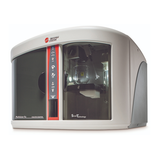
Figure 1 Multisizer 4 Analyzer How the Multisizer 4 Works The Multisizer 4 uses a unique, mercury-free “isolated piston” system to draw suspensions through the aperture at a steady rate and to meter these liquid volumes precisely enough to measure accurate particle concentrations. -
Page 16: Particle Size Determination
The advanced digital electronics used in the Multisizer 4 allow the number of channels to be changed in real time without losing any of the information acquired with other channel spacing. -
Page 17: Displaying Multisizer
Multisizer 4 Specifications Displaying Multisizer 4 Data The Multisizer 4 can display data graphically as number, volume, mass, and surface area size distribution plots, or as tables of values versus size. Both display types can show data as differential or cumulative frequencies. Full data reduction facilities are included for statistical and trend analysis, with export and import capabilities to text and spreadsheet programs via disk files or the Windows Clipboard. -
Page 18: Environmental Conditions
Altitude: Up to 2000 m (5500 ft). Above 7300 m (20,000 ft) unpressurized transport may damage the monitor. • Electrolyte Solutions: All aqueous and non-aqueous electrolyte solutions devised for use with aperture technology are suitable for use with the Multisizer 4. Electrolytes should be compatible with glass, fluoropolymers, fluoroelastomers, and stainless steel. Operational Parameters •... -
Page 19: Regulatory Compliance
Introduction Before You Start: Warnings and Cautions Aperture Diameter Range (µm) Volume Range µm or fL (Nominal Total Standard Extended Total Standard Extended Diameter, µm) 0.4–16 0.4–12 12–16 0.034–905 0.034–2.14×10 905–2.14×10 0.6–24 0.6–18 18–24 0.113–7.24×10 0.113–3.05×10 3.05×10 –7.24×10 1.0–40 1.0–30 30–40 0.524–33.5×10 0.524–14.1×10... -
Page 20: Electrical Warnings
Chemical Warnings • Do not use any electrolyte solutions that are not compatible with the materials of construction. Consult Beckman Coulter, Inc. or its local representative before using any concentrated acids or alkalis in the instrument. • Toxicity, safety, and proper handling procedures for electrolyte and reagents used in particle and cell analysis should be adhered to at all times. -
Page 21: Cautions
Electrical Cautions • Power must be largely free from interference. The Multisizer 4 is CE, UL and CSA compliant with regards to electrical interference but some circumstances may benefit from a constant voltage transformer or regulator. Chemical Cautions •... - Page 22 Introduction Before You Start: Warnings and Cautions xxii PN A51387AB...
-
Page 23: Analyzer Overview
• Enter sample information automatically • Prompt the software to load the Beckman Coulter ST aperture tube size, serial number, and Kd value after the tube has been calibrated • Enter the Multisizer 4 Smart Technology Beaker size, which prompts the Analyzer to move the stirrer into the ideal position for uniform particle distribution. -
Page 24: Automatic Blockage Detection
Extended Dynamic Range The Multisizer 4 is capable of measuring particles in the range of 2% to 80% of the aperture diameter, and in the range of 10% to 80% of the aperture diameter for a 2000-µm aperture tube. The standard range is 2% to 60%;... -
Page 25: Power On/Off Switch
Reducing Noise, page 9-1. NOTE The Multisizer 4 software will display an error message if you attempt to start a sample run while the door is open. For information on components inside the Sample Compartment, see Sample Compartment, page 1-3. -
Page 26: Waste Jar
Multisizer 4 software (see Settings, page 9-6). Waste Tank Electrolyte and Waste Jar Fluid Levels The Multisizer 4 software displays the fluid levels in the Electrolyte Jar and Waste Jars on the Status Panel (Status Panel, page 2-8). The fluid levels in the Electrolyte and Waste Jars are calculated by weight. It is usually necessary to calibrate the weight sensors only once, when you set up the Analyzer. -
Page 27: Control Panel
Method) window in the Multisizer 4 software. To disable the Control Panel stirrer buttons: 1. In the Multisizer 4 software Main Menu, select SOP > Edit the SOM 2. In the Edit the SOM (Standard Operating Method) window, select the Stirrer tab. -
Page 28: Viewing Control Panel Actions In Run Information
Control Panel Viewing Control Panel Actions in Run Information If you use Control Panel buttons to adjust stirrer operation during an analysis run, the Multisizer 4 software stores all changes in stirrer operation, direction, and speed with sample run information. -
Page 29: Stirrer Speed Controls
Options, page 8-15. To use the Bar Code Reader: In the Multisizer 4 software, a Bar Code Reader symbol indicates that you can use the scanner to enter information automatically into appropriate text fields. 1. When you see the Bar Code Reader symbol in a window, hold the ISOTON® II label, ST Aperture Tube, beaker, or sample bar code in front of the Bar Code Reader. -
Page 30: Sample Compartment
Analyzer Overview Sample Compartment Sample Compartment Sample Compartment components are labeled in Figure 1.4 (below). Aperture tube Aperture tube knob Sample Platform Platform Release External Electrode Stirrer Particle Trap LED green, amber, and white status lights Figure 1.4 Sample Compartment Aperture Tube The aperture tube, when in place, is located in the upper left corner of the Sample Compartment (Figure... -
Page 31: Sample Platform
ST Beakers and Accuvette® STs are designed to ensure optimal fluid use and circulation with the locked platform height. To lower the platform, use the platform release (page 1-11). The platform rotates and has two usable sides. One side of the platform has a guide for Multisizer 4 Smart Technology Beakers (Figure 1.5). -
Page 32: Reversing The Sample Platform
Analyzer Overview Sample Compartment Figure 1.6 Platform in Loading Position: Accuvette® ST Side Reversing the Sample Platform To turn the sample platform from the beaker to Accuvette® ST side, or vice versa: 1. Lower the platform to the loading position, if necessary. NOTE Rotate the platform only when it is located at or near the loading position. -
Page 33: Platform Release
Analyzer Overview Sample Compartment Figure 1.7 Reversing the Sample Platform Platform Release The platform release is located on the left edge of the Sample Compartment, above the sample platform in its lowered position (Figure 1.4, D). To lower the platform from its locked analysis position, push the top of the release towards the rear of the compartment. -
Page 34: Particle Trap
Analyzer Overview Sample Compartment NOTE The Multisizer 4 software automatically determines stirrer position for sample runs based on Standard Operating Method (SOM) settings. To change the stirrer position, or park the stirrer outside the beaker, select the appropriate checkboxes in the tab. -
Page 35: Accessories
Accessories Accessories Beakers Multisizer 4 Smart Technology Beakers (ST Beakers) are available in 100 mL, 200 mL, and 400 mL sizes. The unique design of ST Beakers optimizes particle suspension. A spherical interior interrupted by a raised cone creates an unstable area below the stirrer that provides uniform particle distribution. -
Page 36: Aperture Tubes
Analyzer Overview Accessories Aperture Tubes Beckman Coulter manufactures Smart Technology Aperture Tubes designed specifically for the Multisizer 4 Analyzer. Aperture tubes designed for use with the Multisizer 3 will not fit the Multisizer 4. Multisizer 4 Smart Technology Aperture Tubes: •... -
Page 37: Cleaning The Aperture Tube, Beakers, And Accuvette® Sts
Pre-Filtering the Electrolyte and Cleaning Fluid, page 1-17). CAUTION • If Beckman Coulter ISOTON® II is used, the Multisizer 4 must be drained and flushed through with distilled water before carrying out a sodium hypochlorite solution (bleach) disinfection procedure. • If the Multisizer 4 has been subjected to a bleach disinfection procedure, the instrument must be drained and flushed through with distilled water before refilling with ISOTON®... -
Page 38: Cleaning The Analyzer
98% Isopropyl Alcohol (IPA). Drain the system: 1. On the Multisizer 4 software Main Menu bar, select Run > Drain System 2. Remove and empty the Electrolyte and Waste Jars. -
Page 39: Pre-Filtering The Electrolyte And Cleaning Fluid
11. Rinse and fill the Electrolyte Jar with de-ionized water. 12. Repeat Steps 5 through 8 above. Flush the system: 13. Fill the Electrolyte Jar with filtered ISOTON® II. 14. On the Multisizer 4 software Instrument Toolbar, click the button to flush the aperture Flush tube. -
Page 40: Starting The Analyzer
Click Start NOTE The Multisizer 4 performs best when it has reached a steady working temperature. This typically takes 15 minutes from powering on the Analyzer. Preparing the Analyzer for Sample Runs To prepare the analyzer for a calibration, control, or sample analysis run: 1. - Page 41 The sample platform has two usable sides. The ST Beaker side has a built-in guide to ensure that a Multisizer 4 Smart Technology Beaker of any size is in the correct position when you raise the platform. The Accuvette® ST side has a smaller guide for Accuvette STs. The guides ensure that the ST Beaker or Accuvette®...
- Page 42 Analyzer Overview Preparing the Analyzer for Sample Runs 1-20 PN A51387AB...
-
Page 43: Chapter 2: Software Overview
Opening the Multisizer 4 Software To open the Multisizer 4 software: 1. On your desktop, double click the Multisizer 4 software shortcut, or select the program from your program list. 2. The Beckman Coulter Multisizer 4 startup window opens. The window displays the software version, the current date and time, and your security configuration. -
Page 44: Connecting To The Analyzer Using The Software Main Menu
To disconnect the software from the Analyzer, select on the Main Run > Disconnect from Multisizer 4 Menu bar. Multisizer 4 Software Window The Multisizer 4 software window is illustrated below. A Main Menu B Main Toolbar C Status Panel D Viewing Area... -
Page 45: Main Menu
Toolbar (B) or the Instrument Toolbar (F). Main Menu The Main Menu bar appears in the upper left corner of the Multisizer 4 software window. For information on Main Menu bar drop-down menus, see the table below. The Main Menu bar and its drop-down menu items change based on security settings. For example, if you are running the Multisizer 4 software in no security mode, a Configuration drop-down menu appears. - Page 46 • Customize sample information terms • Customize the default Preferences save setting • Set the security level • Choose a language • Configure file and User’s Manual locations • Change Multisizer 4 connection parameters • Configure Bar Code Reader PN A51387AB...
-
Page 47: Main Toolbar Buttons
• View software version information Main Toolbar Buttons The Main Toolbar is located below the Main Menu at the top of the Multisizer 4 software window. The Main Toolbar buttons are shortcuts that duplicate functions available in the Main Menu. -
Page 48: Main Toolbar Buttons: First Group
Save the open file with a new name. Save As Print the open file. The Multisizer 4 software will print the report using Print current Preferences settings. Open the Print Report window. The Print Report window allows you to Report change print settings or update Preferences before printing. -
Page 49: Main Toolbar Buttons: Third Group
This group of buttons is active only when an analysis file is open in the Viewing Area. NOTE If you are running the Multisizer 4 software in security mode, certain Main Toolbar buttons will appear only to user types with sufficient privileges (for example, the button). -
Page 50: Main Toolbar Buttons: Fourth
Open the Concentration Control window and run a concentration control CC Conc. sample. Status Panel The Status Panel, located on the left side of the Multisizer 4 software window, displays elapsed run time, particle count, and concentration information during an analysis run. PN A51387AB... - Page 51 Software Overview Status Panel Before an analysis run begins, the Status Panel displays READY or RUN COMPLETE if the Analyzer is not busy. The Status Panel displays three panes with basic information: the name of the SOP (if loaded), Sample Information (if entered), and SOM information (if entered). •...
-
Page 52: Viewing Area
Panel, page 8-8. Viewing Area The Viewing Area, located in the middle of the Multisizer 4 software window, displays analysis files as graphs, listings, or interpolations. During an analysis run, the Viewing Area displays a graph or listing showing the particle size distribution in progress. -
Page 53: Instrument Toolbar
Software Overview Instrument Toolbar Buttons Instrument Toolbar Buttons The Instrument Toolbar is located at the bottom of the Multisizer 4 software window, below the Viewing Area. Instrument Toolbar buttons duplicate functions also available in the Run drop-down menu. The buttons are divided into three sections: •... -
Page 54: Instrument Toolbar: Reset
Fill Status Bar The Status Bar is located in the lower left corner of the Multisizer 4 software window. The Status Bar text displays the current path and folder (if you are not mousing over a drop-down menu item) or a brief description of a highlighted menu item. -
Page 55: Chapter 3: Installing And Calibrating An Aperture
80% of the aperture diameter for a 2000-µm aperture tube. CAUTION If you select a 20-µm or 30-µm aperture, Beckman Coulter recommends that you follow special cleaning, handling, and operating procedures to accommodate the sensitivity of small apertures. For more information, see Using Small Aperture Tubes (20 µm and 30... -
Page 56: Installing An Aperture Tube
Follow the step-by-step guide provided in the Change Aperture Tube Wizard. The Change Aperture Tube Wizard allows you to verify calibration, test aperture settings, and enter the new aperture tube size and serial number in the Multisizer 4 software. To install an aperture tube: 1. -
Page 57: Using Small Aperture Tubes
Using Small Aperture Tubes (20 µm and 30 µm), page 3-4. 2. If you have not already done so, power on the Analyzer, open the Multisizer 4 software, and connect the software to the Analyzer. 3. In the Multisizer 4 software, select on the Main Menu bar. -
Page 58: Handling Small Aperture
Installing and Calibrating an Aperture Tube Using Small Aperture Tubes (20 µm and 30 µm) Using Small Aperture Tubes (20 µm and 30 µm) Small apertures (20 µm and 30 µm) are fragile and require special handling, cleaning, and operating procedures. -
Page 59: Unblocking Small Aperture
Installing and Calibrating an Aperture Tube Using Small Aperture Tubes (20 µm and 30 µm) Unblocking small aperture tubes The orifices of 20 µm and 30 µm aperture tubes block easily. To unblock the aperture, use the Unblock button in the Instrument Toolbar, or use Standard Operating Method settings to automatically unblock the aperture (see Standard Operating Method: Blockage Detection, page 4-18). -
Page 60: Cleaning The Analyzer Prior To Using A Small
Installing and Calibrating an Aperture Tube Using Small Aperture Tubes (20 µm and 30 µm) Figure 3.2 Closed-Circuit Filtration System Cleaning the Analyzer Prior to Using a Small Aperture Before running analyses with a small aperture tube, clean the system. An effective cleaning procedure includes filling and draining the system multiple times and in multiple cycles, alternating between pre-filtered, de-ionized water and 98% isopropyl alcohol. -
Page 61: Cleaning An St Aperture Tube With A Squeeze Bottle
Installing and Calibrating an Aperture Tube Using Small Aperture Tubes (20 µm and 30 µm) 4. Fill the clean beaker with clean or pre-filtered ISOTON® II or de-ionized water (see Pre-Filtering the Electrolyte and Cleaning Fluid, page 3-5). Make sure that the fluid level is higher than the fluid level during the previous run. -
Page 62: Noise Profile, Clean System (20 Μm Aperture)
Installing and Calibrating an Aperture Tube Using Small Aperture Tubes (20 µm and 30 µm) If you are unable to obtain results similar to those in Figure 3.4 after thoroughly cleaning the system (see Cleaning the Analyzer, page 1-16), your aperture tube may be damaged or blocked. NOTE Figure 3.4 is an example of a clean noise profile. -
Page 63: Using Appropriate Current And Gain
Beckman Coulter recommends that you set the gain to 4 and the current to 600 µA. You can set current and gain using the Change Aperture Tube Wizard (see... -
Page 64: Calibrating The Aperture
Calibrating the Aperture Calibrating the Aperture When you calibrate the aperture, the Multisizer 4 runs an analysis to measure calibrator beads of a predetermined size (ranging from a nominal modal value of 2 µm to 400 µm). Calibrate the aperture with a particle standard that is 10% to 20% of the aperture size (20% is preferred). -
Page 65: Standards,
If you use polystyrene nano-particle calibrators, Beckman Coulter recommends that you keep the concentration level below 2%. Polystyrene nano-particles can bind to system components. After the Multisizer 4 has analyzed a high concentration of nano-particles, it is necessary to clean the aperture tube and external electrode thoroughly. - Page 66 Modal Diameter). Beckman Coulter recommends that you calibrate the system using the standards on the assay sheet supplied with the calibrator. b. If you would like the Multisizer 4 software to prompt the operator to verify calibration at regular intervals: •...
- Page 67 Calibration > Calibrate Aperture settings allow them to create a Standard Operating Procedure (SOP). If the Multisizer 4 software is running with no security, every operator can calibrate the aperture.
-
Page 68: Pausing Or Stopping Calibration,
If you are using a polystyrene nano-particle calibrator, keep the concentration level below 2%. Pausing or Stopping Calibration During calibration, the Multisizer 4 software displays a graph in the Viewing Area. The Status Panel displays elapsed time, total particle count, and particle concentration. To pause or stop calibration:... -
Page 69: Completing The Calibration Run
Stop the calibration. The Multisizer 4 software Stop displays calibration results from the stopped run in the Calibrate Aperture window. Cancel the calibration. The Multisizer 4 software does Cancel not display calibration results. To restart calibration, select Calibration Calibrate Aperture on the Main >... -
Page 70: Obtaining The Mean Kd
Accept New Kd NOTE When you calibrate the aperture, the Multisizer 4 runs an analysis to measure calibrator beads of a predetermined size (ranging from a nominal modal value of 2 µm to 90 µm). Deviations in the Analyzer’s measurement of the calibrator beads determine the calibration constant (Kd) required for the Analyzer to measure the beads at their actual size. -
Page 71: Example
Installing and Calibrating an Aperture Tube Calibrating the Aperture Example This example uses a 10 µm calibrator and a 100 µm Aperture Tube. Table 3.4 Obtaining Mean Kd Value 124.15 125.82 125.13 125.23 125.43 125.13 124.25 125.62 124.25 125.03 MEAN Updating the Mean Kd Value If you have calculated the mean calibration constant (Kd) value for the aperture (page 3-16), you can manually enter the Kd value using the Change Aperture Tube Wizard. -
Page 72: Verifying The Calibration
Installing and Calibrating an Aperture Tube Verifying the Calibration 3. In the Select Aperture Tube window, click . The Edit Aperture Tube List window Edit List opens. 4. In the Edit Aperture Tube List window: a. In the Diameter/Serial Number/Kd/Comment box, click the row you want to edit. b. - Page 73 Installing and Calibrating an Aperture Tube Verifying the Calibration the operator to verify the calibration at regular intervals using the Aperture Calibration Options window (page 3-11). To verify aperture calibration: 1. Select on the Main Menu bar. Calibration > Verify Aperture Calibration 2.
- Page 74 Installing and Calibrating an Aperture Tube Verifying the Calibration 5. When the run is complete, the Verify Aperture Calibration window opens. 6. In the Verify Aperture Calibration window: Table 3.5 Verifying Aperture Calibration If the window displays... Then... The Calibration is OK The measured particle size is within 3% of the actual calibrator size, and the calibration was successful.
-
Page 75: Saving The Calibration File
2. In the Save As window, navigate to the appropriate folder. 3. In the File name field, enter a name for the calibration file. NOTE The Multisizer 4 software uses the .#m4 extension for all run data files, including calibration runs. 4. Click... - Page 76 Installing and Calibrating an Aperture Tube The Change Aperture Tube Wizard To use the Change Aperture Tube Wizard: Select on the Main Menu bar. The Change Aperture Tube Wizard Run > Change Aperture Tube Wizard window opens. The following sections describe how to use the Change Aperture Tube Wizard: •...
-
Page 77: Step 1: Select The New Aperture Tube
(page 3-26). Entering and Editing Aperture Tube Information To enter or update the size, serial number, and Kd of a new aperture tube in the Multisizer 4 software, use the Change Aperture Tube Wizard. PN A51387AB... - Page 78 To enter the tube size and serial number automatically, hold the aperture tube bar code in front of the Bar Code Reader. The Multisizer 4 software will enter the aperture Diameter, Serial Number, and estimated Kd value in the appropriate text fields. For information on using the Bar Code Reader, see page 1-1.
- Page 79 Installing and Calibrating an Aperture Tube The Change Aperture Tube Wizard To edit the aperture tube list: 1. In the Change Aperture Tube Wizard, click Aperture Tube 2. In the Select Aperture Tube window, click . The Edit Aperture Tube List window Edit List opens.
-
Page 80: Step 2: Remove The Currently Installed Aperture Tube
Installing and Calibrating an Aperture Tube The Change Aperture Tube Wizard Step 2: Remove the Currently Installed Aperture Tube The Change Aperture Tube Wizard prompts you to remove the currently installed aperture tube from the Sample Compartment, if necessary. For information on removing an aperture tube, see Installing an Aperture Tube, page 3-2. -
Page 81: Step 4: Place A Beaker Of Clean Electrolyte On The Platform
Platform to the loading position. 5. Place the beaker on the platform (beaker side up). The beaker guides ensure that a Multisizer 4 Smart Technology Beaker of any size will be in the correct position in relation to the aperture tube, electrode, and stirrer when you raise the platform. -
Page 82: Step 6: Fill The System
Setting current and gain determines the electrical pulse size (current) and amplification (gain) that the Analyzer will use as particles pass through the aperture. Unless you are running Service Mode (page 9-18), the Multisizer 4 software sets current and gain automatically. 3-28... - Page 83 600 µA. Higher currents can erode the aperture and create electrical noise. Beckman Coulter recommends that you set the gain to 4, and the current to 600 µA. For information on how to change current and gain settings, see...
-
Page 84: Step 9: Measure Noise Level
Installing and Calibrating an Aperture Tube The Change Aperture Tube Wizard requires a higher current setting. If you are using a more concentrated electrolyte solution, the software will select a lower current setting. A low current with high gain will increase the noise level. A current set too high could saturate the amplifier, damage the aperture orifice, distort your results, or damage cells. -
Page 85: Step 10: Verify Calibration
This step in the Change Aperture Tube Wizard assumes that you have already calibrated the currently installed aperture tube (page 3-10). The Multisizer 4 software will automatically verify the calibration of the aperture tube using the serial number you entered in Step 1: Select the new aperture tube, page 3-23. -
Page 86: Verify Aperture Calibration
Installing and Calibrating an Aperture Tube The Change Aperture Tube Wizard 6. When the verification is complete, the Verify Aperture Calibration window opens. 7. In the Verify Aperture Calibration window: Table 3.6 Verify Aperture Calibration Window If the window displays... Then... -
Page 87: Step 11: All Done
The Control Sample Options menu item is only visible to user types with sufficient security privileges. The system administrator configures security settings. If the Multisizer 4 software is running with no security, every operator can set control sample options, create an SOP, and configure the software. - Page 88 Running a Concentration Control Sample 2. In the Control Sample Options window: a. Select Run a Control Sample. b. If you would like the Multisizer 4 software to prompt you to run a control sample at regular intervals: • Select Hours or Days for the intervals between reminders.
- Page 89 Start 6. The Multisizer 4 software flushes the system and begins the run. 7. When the run is complete, a second Concentration Control window opens and displays results. The window displays a message that the concentration is low or high if the Analyzer measurement deviates from the concentration control by 10% or more.
- Page 90 Installing and Calibrating an Aperture Tube Running a Concentration Control Sample 3-36 PN A51387AB...
-
Page 91: Definitions: Som, Preferences, And
Create a Preferences file to specify view and print settings, including graph, statistics, trend, page setup, and export settings. You can save your Preferences to a file and load the Preferences file into the Multisizer 4 software when needed. You can also include the Preferences file in a Standard Operating Procedure (SOP). -
Page 92: Som),
Settings, page 4-23). SOP > Edit the SOM NOTE The Multisizer 4 software will not allow you to open the SOM Wizard if a Standard Operating Procedure (SOP) is loaded. To remove an SOP, click in the Status Panel, or select Remove SOP on the Main Menu bar. - Page 93 Selecting Analysis Settings: SOM and SOP Using a Standard Operating Method (SOM) NOTE You can exit the SOM Wizard at any time; however, your changes will be lost unless you save them. Go to Step 9 in the SOM Wizard, and click Save Standard Operating Method: Description Use Step 1 of the SOM Wizard (page 4-2) to enter descriptive information, aperture and electrolyte...
-
Page 94: Creating Automatically Generated Analysis File
Selecting Analysis Settings: SOM and SOP Using a Standard Operating Method (SOM) In the Description window: • Click to set automatic file name generation settings (page 4-4). File Name • Click to set all fields to their default values and enter a new Standard Operating New SOM Method. - Page 95 Using File Name Template Codes In the File Name Generation window (page 4-4), each sample information field is preceded by a code that the Multisizer 4 software uses when creating a template for the file name. For example, the template: <F10>_<S10>_<R1>_<U2>.<X>...
-
Page 96: Write-Protecting Saved Analysis
Use Step 2 of the SOM Wizard (page 4-2) or the Control Mode tab of the Edit the SOM window (page 4-23) to enter settings that will determine when an analysis run will end. The Multisizer 4 can end an analysis run based on elapsed time, total count, modal count, or the volume of sample that has passed through the aperture. - Page 97 Selecting Analysis Settings: SOM and SOP Using a Standard Operating Method (SOM) Table 4.3 Control Mode (Step 2): Selections Select and specify... To end the run when... Time The specified number of seconds have elapsed since the run began. Enter any time from 1 to 999 seconds, or select a number from the drop-down list.
-
Page 98: Standard Operating Method: Run
Selecting Analysis Settings: SOM and SOP Using a Standard Operating Method (SOM) Click to specify how often the Waste Tank will empty. In the Waste Tank window, Waste Tank select the intervals by run or time. If you do not select an option to automatically empty the Waste Tank, you can do so manually whenever a run is not in progress by clicking on the Empty... - Page 99 Include Pulse Data is selected. Files will use name parameters specified in Step 1 of the SOM Wizard (page 4-4). The Multisizer 4 software will save the file to the folder displayed in the Status Bar (at the lower left corner of the screen).
-
Page 100: Standard Operating Method: Stirrer
4-11). NOTE The Multisizer 4 will automatically position the stirrer based on the beaker size you select in the SOM. Beckman Coulter recommends that you use Multisizer 4 Smart Technology Beakers with automatic stirrer positioning to ensure consistency and accuracy of results. -
Page 101: Copying Manual Stirrer
The Edit the SOM / Stirrer tab includes an additional feature that allows you to copy manual stirrer settings into the SOM. NOTE The Multisizer 4 software allows the operator to position the stirrer manually only when the operator has entered a non-standard beaker size. PN A51387AB... - Page 102 Selecting Analysis Settings: SOM and SOP Using a Standard Operating Method (SOM) To copy manual settings: 1. Select on the Main Menu bar. SOP > Edit the SOM 2. In the Edit the SOM window, select the Stirrer tab. 3. On the Stirrer tab, select Other in the Sample Beaker pane and enter a non-standard beaker size. 4.
-
Page 103: Standard Operating Method: Threshold, Current And
Selecting Analysis Settings: SOM and SOP Using a Standard Operating Method (SOM) Standard Operating Method: Threshold, Current and Gain Use Step 5 of the SOM Wizard (page 4-2) or the Current and Gain tab of the Edit the SOM window to enter the lower limit of a size distribution as well as the electrical pulse size (current) and amplification (gain) that the Analyzer will use as particles pass through the aperture. -
Page 104: Threshold, Current And Gain (Step 5): Entries Or
Selecting Analysis Settings: SOM and SOP Using a Standard Operating Method (SOM) Table 4.5 Threshold, Current and Gain (Step 5): Entries or Selections In the field... Enter or select... Sizing Threshold The size above which particles are counted (or the lower limit of a size distribution). -
Page 105: Standard Operating Method: Pulse To Size
Selecting Analysis Settings: SOM and SOP Using a Standard Operating Method (SOM) Analyzer as you edit settings. You can use the buttons on the Threshold Current & Gain Current & Gain tab to measure noise level and resistance using the currently installed aperture tube. Standard Operating Method: Pulse to Size Settings Use Step 6 of the SOM Wizard (page 4-2) or the Pulse to Size Settings tab of the Edit the SOM window (page 4-23) to enter the number of bins (channels), bin spacing, and other information that will... - Page 106 • The largest bin must be less than or equal to 60% of aperture diameter. 3. In the Bin Spacing pane, select how the Multisizer 4 software will determine bin spacing: • By an incremental count of particle diameters (Linear Diameter) •...
-
Page 107: Standard Operating Method: Concentration
Selecting Analysis Settings: SOM and SOP Using a Standard Operating Method (SOM) In the SOM Wizard, click to proceed to the next step. Next Standard Operating Method: Concentration Information Use Step 7 of the SOM Wizard (page 4-2) or the Concentration tab of the Edit the SOM window (page 4-23) to enter information about sample volume, density, and dilution. -
Page 108: Standard Operating Method: Blockage
Use Step 8 of the SOM Wizard or the Blockage tab of the Edit the SOM window (page 4-23) to enter blockage detection settings. Based on your settings, the Multisizer 4 will automatically unblock the aperture or stop the run when the system detects a blockage. - Page 109 Selecting Analysis Settings: SOM and SOP Using a Standard Operating Method (SOM) To enter blockage detection settings: In the SOM Wizard - Blockage window, review the Blockage Detection and Blockage Action settings. To change either of these settings, click . The Blockage Detection Settings Blockage Detection window opens.
- Page 110 3. Select Show Details to see detailed blockage detection settings. The window expands. The expanded Blockage Detection Settings window displays the Flow Rate, Count Rate, Aperture Resistance, and Concentration settings that will alert the Multisizer 4 to an aperture blockage and trigger the unblock procedure.
- Page 111 Selecting Analysis Settings: SOM and SOP Using a Standard Operating Method (SOM) • Use change from start of run, Aperture Resistance: 40% • Use Concentration • Blocked for at least 4 seconds 2. In the Use Minimum & Maximum column, select each parameter you want to use. In the corresponding fields, enter the Nominal, Minimum, and Maximum values that will trigger an unblock procedure.
-
Page 112: Saving An Som To A File
SOM Wizard. Done Saving an SOM to a File To save a Standard Operating Method to a file that you can load into the Multisizer 4 software, you can use the SOM Wizard or the Edit SOM window. NOTE The Multisizer 4 software will not allow you to open the SOM Wizard or load, edit, or save SOM settings using the Edit the SOM window if a Standard Operating Procedure (SOP) is loaded. -
Page 113: Editing Som Settings
(page 4-2), you can edit SOM settings. NOTE The Multisizer 4 software will not allow you to load, edit, or save SOM settings if a Standard Operating Procedure (SOP) is loaded. To remove an SOP, click in the Status Panel, or... - Page 114 Settings, page 4-10. Operating Method: Stirrer CAUTION The Multisizer 4 will automatically position the stirrer based on the Smart Technology Beaker size you select in the SOM. • Current & Gain. Enter the lower limit of a size distribution as well as the electrical pulse size (current) and amplification (gain) that the Analyzer will use as particles pass through the aperture.
-
Page 115: The Som Settings (Sop Loaded)
SOM depending on the type of analysis you will be running. NOTE If a Standard Operating Procedure (SOP) is loaded, the Multisizer 4 software will not allow you to edit, save, or load an SOM. To remove an SOP, click in the Status Panel, or select SOP >... -
Page 116: Using A Standard Operating Procedure
NOTE If you are running the Multisizer 4 software in security mode, the option to create a Standard Operating Procedure will not be available to all user types. To create a Standard Operating Procedure: 1. - Page 117 Selecting Analysis Settings: SOM and SOP Using a Standard Operating Procedure (SOP) 4. Click to proceed to the next window in the Wizard, Select an SOM File. Next 5. In the Select an SOM File window, click Select 6. In the Load a Standard Operating Method (SOM) window, navigate to the SOM you want to include, and click .
-
Page 118: Loading An Sop
12. In the Summary of Settings window, click Save 13. In the Save a Standard Operating Procedure window, navigate to the appropriate folder (the Multisizer 4 default is the SOP folder), and click Save 14. To print the SOP summary, click Print 15. -
Page 119: Creating A Preferences File
If you use the Create Preferences Wizard, the Multisizer 4 software guides you through nine steps. You will only be able to save your preferences in the last step of the Wizard. - Page 120 . The Edit Preferences window opens. SOP > Edit Preferences NOTE If the Multisizer 4 software to the Analyzer is not connected, the Edit Preferences window is available by selecting on the Main Menu bar. Different drop-down Preferences > Edit Preferences menus appear in the Main Menu bar when the software is not connected to the Analyzer.
-
Page 121: Window
Setting View and Print Preferences Creating a Preferences File Printing Sample Information The Enter Sample Info dialog box allows you to print either an extensive or short version of the sample information in your report. To choose all sample information: To print all sample and run information in the report, including information previously entered in the Enter Sample Info dialog box (page 6-5), check the Sample Info box in the top left corner of the Printed Report window. -
Page 122: Selecting Graphs, Statistics, And Data For Printing
Setting View and Print Preferences Creating a Preferences File Table 5.1 Printing Sample Information in Reports Sample Info Sample Info and Short Operator Run number Electrolyte Dispersant Aperture diameter Aperture current Size bins Total count Count Control method Acquired Electrolyte volume Analytic volume Sample Background run... - Page 123 Setting View and Print Preferences Creating a Preferences File 3. In the Size Graphs window, select each type of graph you want to print. You can select up to 12 different graph types. Selections appear in the Graph Printing Order field at the bottom of the window.
-
Page 124: Including Statistics In Printed Reports
Averaged Statistics to include this information. Including a Comparison to Sample Specifications in Printed Reports The Multisizer 4 software allows you to compare data files to previously entered sample specifications (page 6-9). In the Size pane of the Preferences / Printed Report window (page 5-2), select Compare to Sample Specifications to include this information in printed reports. -
Page 125: Including A Listing In Printed Reports
Setting View and Print Preferences Creating a Preferences File 3. In the Overlay Statistics window, select each statistic you want to include. Table 5.3 Overlay Statistics Options Select... To print... Total Amount Total number, volume, or surface area in each distribution (the sum of the bins). Mean The mean of each distribution. -
Page 126: Including Interpolation Data In Printed Reports
Setting View and Print Preferences Creating a Preferences File 2. Click to choose which data will appear in the report. The Size Listing window opens. Select 3. In the Size Listing window, select each statistic you want to include. You can select up to seven columns of statistics. -
Page 127: Interpolation Display Data
Setting View and Print Preferences Creating a Preferences File To include a list of interpolation point data: 1. In the Size pane of the Preferences / Printed Report window (page 5-2), select Interpolation. 2. Click to set the interpolation points and range. The Size Interpolation window opens. Select 3. -
Page 128: Including Size Trend Information In Printed Reports
Setting View and Print Preferences Creating a Preferences File 5. In the Range pane: a. Select All to display results from the full range of the analysis. b. Select Between Cursors to display only results between your defined cursors. For information on setting and moving cursors, see page 7-3. - Page 129 Setting View and Print Preferences Creating a Preferences File To change the d0 values to custom percentages, click and enter new values in Custom Points the Custom Trend Points window. These values allow you to divide the particle distribution of each run by percentage of particle size above and below a certain diameter.
-
Page 130: Including Size Statistics In Printed Reports
Including Filtration Efficiency in Printed Reports In order to include filtration efficiency in printed reports, you will need to compare two or more sample analyses so that the Multisizer 4 software can calculate filtration efficiency. To include filtration efficiency data: 1. - Page 131 Setting View and Print Preferences Creating a Preferences File To show pulse data in a graph: 1. In the Pulse Data pane of the Preferences / Printed Report window (page 5-2), select Graph. 2. Click . The Pulse Graph window opens. Select 3.
-
Page 132: Including Blockage Monitor Data In Printed Reports
Graph, a Listing, or both. NOTE The Multisizer 4 software saves blockage monitor data with every analysis. Printed reports can display blockage monitor data independently of blockage settings in the SOM. To show blockage monitor data in a graph: 1. -
Page 133: Setting The Print Order For Reports
Setting View and Print Preferences Creating a Preferences File 3. In the Blockage Monitor Listing window, select the blockage monitor data you want to include in the listing. The display sequence appears in the lower left corner of the window. 4. -
Page 134: Statistics Display Preferences
Setting View and Print Preferences Creating a Preferences File Table 5.5 Statistics Display Preferences Statistic Type Description Percentile To display percentiles, select < less than and > greater than and enter percentile boundaries. You can define up to eight percentiles. Range •... -
Page 135: Using Statistical Category Names
Setting View and Print Preferences Creating a Preferences File Using Statistical Category Names In the Preferences / Statistics window, click to define and name size categories. Size Categories category specifications allow you to simplify statistical results for easy interpretation in printed reports. - Page 136 Setting View and Print Preferences Creating a Preferences File For more information on averaging and trend statistics, see Files, page 7-20 Averaging Analysis Creating a Size Trend Analysis, page 7-22. In the Preferences /Averaging and Trend window: • In the Average Weighting pane, select how you will look at analysis results (typically Number/mL) when multiple files are averaged.
-
Page 137: Preferences: Export
Setting View and Print Preferences Creating a Preferences File • In the Custom Trend Points pane, set trend percentiles, if desired. d[X] values allow you to divide the particle distribution of each run by percentage of particle size above and below a certain diameter. -
Page 138: Reports,
Setting View and Print Preferences Creating a Preferences File 6. In the Export Folder pane, allow the Current folder (default) or select the Custom folder and browse to a new file location. The new file path appears in the field. The exported file name is the analysis file name with the export extension. -
Page 139: Preferences: Graph Options
Setting View and Print Preferences Creating a Preferences File Preferences: Graph Options Use Step 6 of the Create Preferences Wizard (Graph Options) or the Graph Options tab of the Edit Preferences window to select display, style, and color options for printed graphs. To proceed from Step 5 to Step 6, click Next For information on how to open the Create Preferences Wizard and the Edit Preferences windows,... -
Page 140: Reports,
1. In the Window Colors pane, select Graphs, Graph Statistics, Statistics, Listings, or Warning Text. 2. To change text colors for the selection only (for example, Graphs): a. Click to return to Multisizer 4 defaults. Default Colors b. Click ) to open the Color window. Select a color in the palette or define a custom Text Color color. -
Page 141: Preferences: View Options
Setting View and Print Preferences Creating a Preferences File Preferences: View Options Use Step 8 of the Create Preferences Wizard (View Options) or the View Options tab of the Edit Preferences window to select the default graph or listing type that will appear when you complete an analysis, and to select other analysis viewing preferences. -
Page 142: Reviewing Your Preferences Settings
Setting View and Print Preferences Creating a Preferences File Table 5.6 Preferences Wizard: Set View Options View Preferences Description Volume Units Select the volume unit you want to use. Specific Surface Area Units Select the surface area units you want to use. Blank Subtract Select Allow negative results if you want to display the negative result when a bin in the blank run contains more particles than a bin in the... -
Page 143: Saving A Preferences File
If you are using only one set of preferences, you can configure the Multisizer 4 software to automatically save updates to your preferences to a default file when you exit the software. -
Page 144: Automatically Updating The Default Preferences File
NOTE If you are running the Multisizer 4 software in security mode, certain user types may not have sufficient security privileges to view the Configuration menu. In security mode, the Configure Preferences menu item appears in the Administrator or Supervisor drop-down menu if the user has logged in as an administrator or supervisor, respectively. -
Page 145: Analyzing A Sample
Preparing the Analyzer for Sample Runs, page 1-18. Before starting a sample run: 1. Power on the Analyzer, open the Multisizer 4 software, and connect to the Analyzer (see Opening the Multisizer 4 Software, page 2-1). 2. Fill the system with electrolyte solution. -
Page 146: Loading An Som
Analyzing a Sample Analyzing a Sample determines sample run settings, while the Preferences file determines view and print specifications. • For information on creating a Standard Operating Method, see page 4-2. • For information on setting Preferences, see page 5-1. •... -
Page 147: Removing An Sop
SOP files are identified by the extension .sop. Removing an SOP When you load a Standard Operating Procedure, the Multisizer 4 software will not allow you to open an SOM, make changes to it, and then save it under another name. -
Page 148: Verifying Som Settings
Analyzing a Sample Analyzing a Sample Table 6.1 Copy and Print Preference Settings If you want to... Then... Copy the Preferences list to the 1. Click Print clipboard 2. In the Print or Copy List Box Contents window, select Copy all lines to clipboard. -
Page 149: Entering Sample Information
Analyzing a Sample Analyzing a Sample Table 6.2 Verify SOM Settings If you want to... Then... Copy the SOM settings to the clipboard 1. Click Print 2. In the Print or Copy List Box Contents window, select Copy all lines to clipboard. 3. -
Page 150: Entering Sample Info For Next
The number of the run. In general, enter “1” in this field, and reset the run number to “1” if you are re-running the sample. The Multisizer 4 software will automatically increment the run number for multiple runs. You can use this field to create sequential file names for each run by setting file name preferences in the SOM (page 4-4). -
Page 151: Editing Sample Information
NOTE The option to edit sample information after a run is available only to user types with sufficient security privileges. If the Multisizer 4 software is running with no security, every operator can edit sample information. To update or enter sample information after an analysis run: 1. - Page 152 Analyzing a Sample Analyzing a Sample To enter sample specifications: 1. Select on the Main Menu bar. The Create Sample Sample > Create Sample Specifications Specifications window opens. 2. In the Create Sample Specifications window: a. In the Statistics Type pane, enter the type of bin weighing and the particle size range for comparison.
-
Page 153: Editing Sample Specifications
NOTE The option to edit sample specifications is available only to user types with sufficient security privileges. If the Multisizer 4 software is running with no security, every operator can edit sample specifications. To update or enter sample specifications after an analysis run: 1. -
Page 154: Editing Size Data
Replace 4. Click to save your settings. Running an Analysis To run an analysis, follow the steps below to prepare the Analyzer and Multisizer 4 software and run the analysis. To run an analysis: 1. Prepare the Analyzer (page 1-18). - Page 155 Analyzing a Sample Analyzing a Sample 8. Select on the Main Menu bar (or click in the Instrument Toolbar). Run > Start Start • If the Extended Size Range feature is enabled in the SOM (see Standard Operating Method: Threshold, Current and Gain) and the large particle count exceeds the specified threshold, a notification dialog will appear: •...
-
Page 156: Sample Analysis Variations
6. Sieve, filter, or use another suitable method to remove the particles from the suspension that will block the smaller aperture. 7. Repeat Step 2 through Step 5. The Multisizer 4 can combine a maximum of five analyses in one multi-tube overlap file. -
Page 157: Determining Particle Concentration Using Time Mode
2 mL. In larger aperture tubes, this volume of fluid passes through the aperture too quickly to provide accurate statistical results. NOTE The Multisizer 4 uses small amounts of electrolyte for pre- and post-analysis stabilization. As a result, calculated volume is approximate. NOTE If you are measuring heavy particles, Beckman Coulter recommends that you thicken the electrolyte to increase particle suspension, reduce the flow rate, and produce less noise. -
Page 158: Using Blank Runs
When analyzing low concentration samples, a background analysis is required for accurate results. NOTE Beckman Coulter recommends that you run a background (blank) analysis for every batch of analyses that uses the same electrolyte. Running a Blank Analysis To run a blank analysis: 1. -
Page 159: Enabling Blank Subtraction For Analysis Runs
Analyzing a Sample Using Blank Runs Enabling Blank Subtraction for Analysis Runs After you run a blank analysis (page 6-14), you can set the software to automatically subtract electrolyte background from sample analysis runs. To subtract the electrolyte background from analysis runs: 1. - Page 160 Analyzing a Sample Using Blank Runs 6-16 PN A51387AB...
-
Page 161: Chapter 7: Working With Analysis Files
Standard Operating Procedures (SOPs). Creating SOPs allows you to set specific run, view, and print preferences for different types of analysis runs (page 4-26). You can change how the Multisizer 4 software displays an analysis file in the following ways: •... -
Page 162: Viewing Analysis Files
Working with Analysis Files Viewing Analysis Files • If you want to print a graph or listing as it appears on the screen, without changing Print Report settings, select on the Run Menu bar. RunFile > Print Viewing Analysis Files Changing the Display of an Open File To change the display of an open analysis file: 1. -
Page 163: Calculate Menu
Working with Analysis Files Viewing Analysis Files NOTE If you select in the drop-down menu, Differential + Cumulative < Differential + Cumulative > Graph a new menu appears to the right of the menu. The menu allows you to select Cursor Display Cursor... -
Page 164: Viewing Listings
Working with Analysis Files Viewing Analysis Files Viewing Listings To display analysis data as a numerical list: 1. Select on the Run Menu bar. View > Listing 2. Open the drop-down menu a second time and select the type of listing ( , or View Size... -
Page 165: Pulses Column Format
Working with Analysis Files Viewing Analysis Files c. Select Between Cursors to display only results between your defined cursors. For information on setting and moving cursors, see page 7-3. d. Select From and enter specific points in the From and to fields to define statistical limits. 3. -
Page 166: Blockage Monitors Column Format
Working with Analysis Files Viewing Analysis Files Blockage Monitors Column Format If you select then select , the Blockage Monitor Listing window View > Listing Blockage Monitors opens when you select Listing > Column Format To select the data columns that will appear in the Blockage Monitor listing: 1. -
Page 167: Size Interpolation Data
Working with Analysis Files Viewing Analysis Files 2. Select on the Run Menu bar. Interpolation > Size Interpolation 3. In the Size Interpolation window: a. In the Interpolation Type pane, select Size to or to Size. • Select Size to if you want to create interpolation points based on particle diameter size (that is, particle diameters define bin edges). -
Page 168: Changing The Column Display
Working with Analysis Files Viewing Analysis Files e. In the Range pane: • Select All to display results from the full range of the analysis. • Select Between Cursors to display only results between your defined cursors. For information on setting and moving cursors, see page 7-3. •... -
Page 169: Comparing Statistics To Sample Specifications
1. Select on the Run Menu bar. Calculate > Statistics 2. In the Statistics window, click . The Multisizer 4 will include the statistics you save when Save you save the analysis run. The statistics you save in the window will appear when you select Calculate >... - Page 170 2000-µm aperture, as shown below). 2% to 60% 10% to 60% c. In the Bin Spacing pane, select how the Multisizer 4 will determine bin spacing: • By an incremental count of particle diameters (Linear Diameter) •...
-
Page 171: Converting Pulses To Size Between Cursors
Working with Analysis Files Viewing Analysis Files d. In the Options pane, select one or more of the following, if desired: • Pulse Edit. Select this option if you have a narrow distribution and want to ensure accurate analysis results by eliminating large pulses. Particles that do not pass through the center of the aperture tend to produce wider pulses. -
Page 172: Printing Report(S) For One Or More Analysis Files
Working with Analysis Files Viewing Analysis Files Printing Report(s) for One or More Analysis Files If you want to print reports for multiple analysis runs or for a single analysis run that is not open in the Viewing Area: 1. Select on the Main Menu bar. - Page 173 Working with Analysis Files Viewing Analysis Files d. Click . A second Print Reports window opens. 3. In the Print Reports window, click . For information on how to change printer settings Print or Preferences using the Print Report window, see page 7-14. PN A51387AB 7-13...
-
Page 174: Printing A Report Of An Open Analysis File
Working with Analysis Files Viewing Analysis Files Printing a Report of an Open Analysis File To print a report for an analysis file that is open in the Viewing Area: 1. Select on the Run Menu bar. The Print Report window opens. RunFile >... -
Page 175: Printing With Current Analysis Settings
Working with Analysis Files Viewing Analysis Files Table 7.3 Open Analysis File Print Options Select this option... To... Print a report for the current Print a report for the open file in the Viewing Area only. This option is only file only available when multiple files are open. -
Page 176: Saving An Analysis File
When you have made your selections, including graph size, color, and font, click Print Saving an Analysis File The Multisizer 4 can automatically save analysis data based on Standard Operating Method settings, or you can save sample data to a file when the analysis is complete. Saving Analysis Data Automatically To automatically save analysis data, select appropriate Run Settings in the current Standard Operating Method and enter sample information before the run. -
Page 177: Saving Analysis Data Manually
Working with Analysis Files Viewing Analysis Files NOTE Selecting Include Pulse Data will increase the file size significantly. 5. Click . The Select the Run Folder window opens. Folder 6. In the Select the Run Folder window: a. Select Use the current folder or Use a custom folder. If you are using a custom folder, click and navigate to the desired folder. -
Page 178: Importing A File
Working with Analysis Files Viewing Analysis Files Importing a File You can import data from another program or transfer a size distribution from another instrument. To import a file: 1. Select on the Main Menu bar. File > File Tools > Import Size Data 2. -
Page 179: Working With Multiple Analysis Files
Working with Analysis Files Working with Multiple Analysis Files Working with Multiple Analysis Files Using Overlay Files Opening files for overlay allows you to view multiple analysis results on the same graph. To open files for overlay: 1. Select on the Main Menu bar. The Overlay window opens. File >... -
Page 180: Saving An Overlay File
If you move or delete the original files, the overlay file will not open. Averaging Analysis Files The Multisizer 4 allows you to average the results of multiple analyses and view or print averaged statistics in a listing or graph. -
Page 181: Opening Files For Averaging
Working with Analysis Files Working with Multiple Analysis Files Opening Files for Averaging To view the average of two or more analysis files: 1. Select on the Main Menu bar. The Average window opens. File > File Tools > Average 2. -
Page 182: Opening A Saved List Of Averaged Files
Working with Analysis Files Working with Multiple Analysis Files original files, but points to the original files in their current location. If you move or delete the original files, the average file will not open. To save an average as a self-contained analysis file: 1. -
Page 183: Opening Files For A Size Trend
Working with Analysis Files Working with Multiple Analysis Files Opening Files for a Size Trend To view size trend data for two or more analysis files: 1. Select on the Main Menu bar. The Create Size Trend window File > File Tools > Create Size Trend opens. -
Page 184: Opening A Size Trend
Working with Analysis Files Working with Multiple Analysis Files To save a size trend: 1. Select on the Run Menu bar. RunFile > Save RunFile > Save As 2. In the Save As window, navigate to the appropriate folder and enter a file name in the File Name field. -
Page 185: Saving A Merged Run
Working with Analysis Files Working with Multiple Analysis Files 2. In the Merge Runs window: a. In the Folders box, double click the appropriate folder name. The folder contents appear in the Files box. b. In the Files box, click to highlight the file(s) you want to merge. To highlight multiple analysis files, hold the Ctrl key down while clicking each file name, or click one file and drag over the files to be included. -
Page 186: Filtration Efficiency
Filtration Efficiency Filtration Efficiency The Multisizer 4 allows you to measure filtration efficiency by comparing particle number and/or sizes in two runs, one before and one after filtering the sample. For example, you can measure overall filtration efficiency. If the Analyzer counts 1000 particles in the first run, and, after applying the filter, counts 100 particles, then filtration efficiency is 90%. -
Page 187: Configuring Software And Security
The Configuration drop-down menu and certain configuration items in the Windows drop-down menu appear in the Multisizer 4 Main Menu bar only when you are running the software in No security mode. When running the software in a security mode, configuration menu items are available to Administrator and Supervisor accounts only. - Page 188 Configuring Software and Security Security Modes and Configuration Main Menu: No security. Not connected to the Analyzer. Configuration options are available to all users. Main Menu: Medium security, Operator Mode. Username and password required. Configuration options are available to Administrator and Supervisor accounts only. Main Menu: Low security, Operator Mode.
-
Page 189: Customizing Main Menus
8-7. NOTE When you hide a menu item, the Multisizer 4 software removes the item until you reinstate it using the Customize Main Menus window. Unlike menu items that are hidden, items that are temporarily unavailable during normal software function appear greyed out (for example, Run >... - Page 190 Configuring Software and Security Customizing Main Menus To customize Main menus: 1. Select on the Main Menu bar. Configuration > Customize Main Menus 2. In the File pane, select the menu items you want to hide. NOTE Some items in the File pane are located in .
-
Page 191: Customizing Run Menus
Changes take effect immediately. You do not need to restart the Multisizer 4 software. NOTE When you hide a menu item, the Multisizer 4 software removes the item until you reinstate it using the Customize Main Menus window. Unlike hidden menu items, items that are temporarily unavailable during the normal functioning of the software appear greyed out (for example, Run >... - Page 192 Configuring Software and Security Customizing Run Menus To customize Run menus: 1. In the RunFile pane, select menu items in the RunFile drop-down menu that you want to hide. 2. In the Edit pane, select menu items in the Edit menu that you want to hide. 3.
-
Page 193: Customizing Toolbars
• To remove the Instrument Toolbar, clear the Show Instrument Toolbar checkbox. • To return to the default Multisizer 4 software button configuration, click Default Buttons • To add or remove a Main Toolbar button, or to change the button order, click Customize The Customize Toolbar window opens. -
Page 194: Customizing The Status Panel
4. In the Toolbars window, click when you are finished. Changes take effect immediately. You do not need to restart the Multisizer 4 software. Customizing the Status Panel You can customize the colors that appear on the Status Panel, adjust warning levels, set the speed and volume of audible clicks, and change the location of the Status Panel. -
Page 195: Panel,
Status Bar. Coincidence correction adjusts for incidences of two particles passing through the aperture at the same time. Based on the size distribution, the Multisizer 4 adjusts the count by replacing large pulses with smaller pulses at a statistically correct size. -
Page 196: Customizing Sample Info Names
Operator to Technician, or specify a variable you will use in sample runs by changing Variable 1 to pH. The new terms you configure in the Multisizer 4 software will appear in the Enter Sample Info window, the Edit the SOM (Standard Operating Method) window, throughout the software, and in printed reports. -
Page 197: Customizing Recent File And Folder Lists
File submenus (Recent Folders and Recent Files). You can configure the Multisizer 4 software to include a file or folder in the Recent Folders or Recent Files list when the file or folder is opened, used in an overlay (page 7-19), and/or saved. -
Page 198: Selecting A New Folder From The Recent Folder List
(page 4-2). If you enter 0, no recent runs will appear. 5. In the Update Lists When pane, select options to define when the Multisizer 4 software will add a file or folder to the recently used list. By selecting a combination of checkboxes, you can choose to add a file to the list only when the file is saved, any time a file is opened, and/or when the operator adds a file to an overlay (page 7-19). -
Page 199: Customizing The Save Preferences Default Setting
Customizing the Save Preferences Default Setting Customizing the Save Preferences Default Setting You can determine whether the Multisizer 4 software will automatically save changes to default Preferences settings the operator makes during an analysis run session. To automatically save new Preferences settings after each run session: 1. -
Page 200: Multisizer 4 Configuration Options
2. Select a language listed in Choose your language and click Multisizer 4 Configuration Options The Multisizer 4 Configuration window allows you to set default folder locations for SOM, SOP, and Preferences files. You can also use this window to select new Help files (User Manual, Appendix, and Bibliography) as updates become available. -
Page 201: Bar Code Reader Configuration Options
3. Navigate to and select the appropriate folder, and click to close the Browse window. 4. Click next to User’s Manual to select the location of the Multisizer 4 User Manual. Select 5. Select Enable Dialog Help to display a shortcut to context-sensitive online Help topics in Multisizer 4 software windows. -
Page 202: Customizing Security Settings
UPC symbologies. Click Customizing Security Settings You can run the Multisizer 4 with no security or one of four levels of password-protected security. With the exception of 21 CFR Part 11 security, the administrator determines the user privileges that will be associated with each security level (Low, Medium, or High). - Page 203 Configuring Software and Security Customizing Security Settings define requirements for submitting documentation in electronic form and the criteria for approved electronic signatures. For more information, see Regulatory Compliance, page 10-1. To create an Administrator account: 1. In the Main Menu bar, select .
-
Page 204: Logging In
Configuring Software and Security Customizing Security Settings Logging In Some security settings require all operators to log in with a username or a username and password. When log-in is required, the Log In window will appear when a user opens the software. If the user does not have log-in privileges, the software is locked. -
Page 205: Administrator Menu Options
Configuring Software and Security Administrator Menu Options Administrator Menu Options When a user with Administrator privileges logs in to the Multisizer 4 software, the Main Menu bar displays the Administrator drop-down menu. The Administrator drop-down menu allows you to: •... -
Page 206: Customizing User Privileges
Configuring Software and Security Administrator Menu Options Customizing User Privileges To set security level and customize user privileges: 1. Log in as Administrator. 2. Select on the Main Menu bar. The User Privileges window opens. Administrator > User Privileges 3. In the Set default user privileges pane, select a security level and click . -
Page 207: Troubleshooting
• Low aperture current. If you are using a small aperture tube or a concentrated electrolyte solution, the Multisizer 4 software will automatically select a low current/high gain setting. • High aperture current. If the aperture current is set too high, the electrolyte solution in the aperture can heat or boil, causing noise. -
Page 208: Measuring The Noise Level
If the threshold is set too low, increase the threshold in the Create SOM Wizard (page 4-2) or the Edit the SOM window (page 4-23). If noise levels remain high or variable after troubleshooting, contact Beckman Coulter Field Service (page 9-15). -
Page 209: Adjusting The Metering Pump
Service (page 9-15). Setting the Vacuum Regulator The Multisizer 4 software resets the Waste Tank vacuum on start-up and at regular intervals. A Waste Tank vacuum malfunction can result from a mechanical flaw in the Analyzer. When the Waste Tank vacuum is malfunctioning, the Multisizer 4 software may display the following error message:... -
Page 210: Setting Custom Measurement Intervals
Mode, click to save your settings. System Error: Unable to Measure Gain Stage Offsets If the Analyzer is unable to measure gain stage offsets automatically, the Multisizer 4 software will display the following error message: Unable to measure gain stage offsets If this error message appears, power off the Analyzer, close the Multisizer 4 software, and restart the system. -
Page 211: Resolving Error Messages On Software Startup
Resolving Common Problems Resolving Error Messages on Software Startup If the Multisizer 4 software cannot find Preferences, Standard Operating Method, and other files on startup, one or more error messages will appear. If one or more error messages appear on startup, use the Multisizer 4 Configuration window to reset default folder(s) for settings, preferences, and run files. -
Page 212: Viewing Advanced Multisizer Settings
Troubleshooting Viewing Advanced Multisizer Settings Viewing Advanced Multisizer Settings Waste Tank Settings When the software is connected to the Analyzer, the Status Panel displays the Waste Tank fluid level. You can manually empty the Waste Tank into the Waste Jar at any time by clicking Empty in the Instrument Toolbar or selecting on the Main Menu bar. -
Page 213: Vacuum Settings
. The Status Panel displays CALIBRATING WASTE TANK. SERVICE > Calibrate Waste Tank CAUTION Beckman Coulter does not recommend that you use the options available in Service Mode without the assistance of a trained Service Representative. To contact a representative, see... -
Page 214: Flow Rate Error Messages
When the flow rate is too low, the Multisizer 4 software will display one of the following error messages: Flow Rate is too low, the aperture may be blocked Flow Rate is too low. -
Page 215: Fill, Flush, And Drain Settings
Troubleshooting Viewing Advanced Multisizer Settings To adjust flow settings: 1. Select on the Main Menu bar. Run > Troubleshooting > Enter Service Mode NOTE Entering Service Mode will allow you to change default settings in the Troubleshooting menu. If you do not enter Service Mode, settings in the Troubleshooting menu will appear as read-only values. - Page 216 CAUTION It is not possible to change the system flush time setting unless you are running Service Mode. Beckman Coulter does not recommend that you use the options available in Service Mode without the assistance of a trained Service Representative (see Requesting Service and Technical Support, page 9-15).
-
Page 217: Draining The System
CAUTION It is not possible to change the system drain time setting unless you are running Service Mode. Beckman Coulter does not recommend that you use the options available in Service Mode without the assistance of a trained Service Representative (see Requesting Service and Technical Support, page 9-15). -
Page 218: Aperture Resistance Settings
The electrolyte level may be too low. Reset Multisizer 4 aperture resistance defaults only if you are using an electrolyte with unusually high current resistance. -
Page 219: Calibrating The Electrolyte And Waste Jars
µA. • If Enable Aperture Current Checking is selected, the Multisizer 4 software verifies that the system can supply the voltages selected in the Measurement Current, Initial Current, and analysis current and gain fields. If the current exceeds the setting in the Maximum Voltage... - Page 220 Calibrate Electrolyte Jar and Waste Jar Level Sensors window opens. NOTE When calibrating Electrolyte and Waste Jars, Beckman Coulter recommends that you calibrate the Electrolyte Jar empty, then full, to leave the jar in the full state. When calibrating the Waste Jar, calibrate the jar full, then empty, to leave the jar in the empty state.
-
Page 221: Working With Field Service
Each button opens your default email editor and includes the email address of a Field Service Representative in your area. Identifying the Instrument When you contact Beckman Coulter Field Service, the Service Representative will require software and firmware information in order to help you resolve the problem. To obtain information about the Analyzer: 1. -
Page 222: Updating Firmware And Fpga Software
1. Select on the Main Menu bar. Help > About 2. In the Beckman Coulter Multisizer 4 window, locate and record the software version number at the top of the window, and click Updating Firmware and FPGA Software While the Multisizer 4 software runs on a PC connected to the instrument, firmware is the programming and software that runs within the Analyzer. -
Page 223: Viewing The Instrument Schematic
Main Menu bar. Lamp (on/off) • Select Always on top to keep the Instrument Schematic window visible during an analysis run. You may need to restart the Multisizer 4 software for this setting to take effect. PN A51387AB 9-17... -
Page 224: Viewing The Error Log
Troubleshooting Working with Field Service Viewing the Error Log When you contact Beckman Coulter Field Service, the Service Representative may ask you to open the error log. To open the error log: 1. Select on the Main Menu bar. The MS4ERROR.LOG Run >... -
Page 225: Chapter 10: Regulatory Compliance
FDA Requirements The Multisizer 4 control software has been designed to allow users to comply to the electronic records and signatures rule. Any organization deciding to employ electronic signatures must declare to the FDA their intention to do so. -
Page 226: Security Controls
[Section 11.10 Paragraph (a)]. The complete and overall validation of the system, as developed by the organization, ensures the integrity of the system and its data. The features of the Multisizer 4 software are designed to comply with the specifications of these regulations. -
Page 227: Audit Trail
File History and Audit Trail File History or auditing can be enabled for any file created by the Multisizer 4 software. After auditing has been enabled for a file, it cannot be disabled, nor can it be bypassed. Under these conditions, all changes made to a file are automatically recorded. -
Page 228: Setting Audit Trail Options
File History and Audit Trail Setting Audit Trail Options In addition to the auditing associated with the electronic file itself, the Multisizer 4 software offers two additional levels of auditing. First, a general system audits records and stores information at a system level (for example, who logged in when, or when users were added to the system). -
Page 229: Maintaining Electronic Signatures
Select a user type from the Type drop-down list. 4. Click The “identification code ” or username of each Multisizer 4 user must be unique. Users must also supply a password to access the Multisizer 4 software. Passwords can be controlled to prohibit the use of duplicates and to force the selection of new passwords after a prescribed period of time. -
Page 230: Applying Electronic Signatures
This section of the document represents the “heart” of electronic signature application. To comply with these provisions, the Multisizer 4 software uses the application of the username and password to authenticate the user making and saving the changes, in conjunction with file history and audit trails, to independently record the date and time of operator entries and actions that create, modify, or delete electronic records. -
Page 231: Additional Security Features
Regulatory Compliance Additional Security Features Additional Security Features The Multisizer 4 software offers two important additional levels of security not required by the regulations. These levels make it easier to define and implement system policies: • Data Mirroring. This feature, which can be accessed only in administrator mode, allows the administrator to securely store files in a separate location and in addition to locations specified by a user. - Page 232 Regulatory Compliance Additional Security Features 10-8 PN A51387AB...
- Page 233 Index preparing for sample runs, 1-18 starting, 1-18 Accessories start-up dialog, 1-18 Accuvette STs, 1-13 version number, 9-16 aperture tubes, 1-14 Analyzing and Attention lights, Beakers Aperture calibrators, 1-13 calibrating, 3-10, 3-13 Accuvette STs choosing calibrator size, 3-10 cleaning, 1-15, Aperture calibration.
- Page 234 Index configuring, 8-15 Context-senstive help. See Help, 8-15 Beakers Control Panel, 1-3, cleaning, 1-15, buttons, guides, Control sample. See Concentration control sample placing on platform, 3-27 Create Preferences Wizard, Blank analysis. See Blank run Averaging and Trend, 5-17 Blank run Export, 5-19 enabling blank subtraction,...
- Page 235 7-25 Metering pump adjusting, 3-28, Help purging, enabling, 8-15 Multisizer 4 components, features, Multisizer 4 accessories. See Accessories Instrument Toolbar Multisizer 4 software Fluid Control buttons, 2-12 customizing field names, 8-10 Reset button, 2-12 Instrument Toolbar. See Instrument Toolbar Run buttons,...
- Page 236 Index measuring, 3-30, converting, reducing, 3-5, converting between cursors, 7-11 converting for widest distributions, 7-11 ON light, Overlay files, 7-19 Recent files list moving between, 7-25 customizing, 8-11 opening, 7-20 Recent Folders list saving, 7-20 customizing, 8-11 Overlay statistics Regulatory compliance, 10-1 additional security features, 10-7...
- Page 237 Index entering, Software configuration, printing, Software startup Sample Info Names resolving errors, customizing, 8-10 SOM (Standard Operating Method) Wizard. See SOM Sample Menu, Wizard Sample runs SOM Wizard, merging, 7-24 Blockage, 4-18 preparing for, Concentration Information, 4-17 selecting analysis settings, Control mode, Sample specifications Description,...
- Page 238 Index viewing, reducing noise, Status Bar, 2-12 resolving software startup errors, Status Panel, setting the vacuum regulator, customizing, updating Multisizer 4 software, 9-16 Stir On button, viewing aperture resistance settings, 9-12 Stirrer viewing instrument schematic diagram, 9-17 direction controls, viewing system drain time,...
Need help?
Do you have a question about the Multisizer 4 and is the answer not in the manual?
Questions and answers