Table of Contents
Troubleshooting

Related Manuals for Beckman Coulter UniCel DxH 800


Summary of Contents for Beckman Coulter UniCel DxH 800
- Page 1 Instructions for Use ® UniCel DxH 800 ® Coulter Cellular Analysis System Hematology Specimen Processing Module with System Manager 629743AE March 2009 Beckman Coulter, Inc. 4300 N. Harbor Blvd. Fullerton, CA 92835...
- Page 2 ® ® UniCel DxH 800 Coulter Cellular Analysis System Instructions for Use PN 629743AE (March 2009) www.beckmancoulter.com Find us on the World Wide Web at: Beckman Coulter Ireland, Inc. Mervue Business Park, Mervue Galway, Ireland 353 91 774068...
-
Page 3: Revision History
Revision History Initial Issue, 11/2008 Software Version 1.0 Issue AB, 12/2008 Software Version 1.0 Issue AC, 12/2008 Software Version 1.0.2.0 Issue AD, 03/2009 Software Version 1.1 Links to the changes are listed below: • Updated Configure Reagents section, 9-4. • Added Database Recovery Procedure, 10-32. •... - Page 4 This document applies to the latest software listed and higher versions. When a subsequent software version affects the information in this document, a new issue will be released to the Beckman Coulter Web site. For labeling updates, go to www.beckmancoulter.com and download the latest version of the manual or system help for your instrument.
-
Page 5: Safety Notice
Beckman Coulter representative. Beckman Coulter, Inc. urges its customers to comply with all national health and safety standards such as the use of barrier protection. This may include, but is not limited to, protective eyewear, gloves, and suitable laboratory attire when operating or maintaining this or any other automated laboratory analyzer. - Page 6 • This equipment is used in a manner other than specified. Operate the instrument as instructed in the product manuals. • You introduce software that is not authorized by Beckman Coulter into your computer. Only operate your system’s software with software authorized by Beckman Coulter.
-
Page 7: Table Of Contents
History, iii Safety Notice, v INTRODUCTION, xxxi System Overview, 1-1 CHAPTER 1: Intended Use, 1-1 Parameters, 1-2 UniCel DxH 800 SYSTEM, 1-3 Hardware, 1-4 Overview, 1-4 Inter-Unit Connections, 1-4 Front View of the SPM, 1-7 Functional Modules, 1-7 Specimen Transport... - Page 8 Contents Previous/Next Icons, 1-21 Single-Tube Presentation Icon, 1-21 Status Area, 1-21 Status Bar, 1-22 Alert Status Icons, 1-22 Utility Icons, 1-23 System Icons, 1-24 Local Navigation Bar, 1-24 Consumables and Supplies, 1-25 Recommended Reagents, 1-25 Material Safety Data Sheets (MSDS), 1-26 Recommended Controls and Calibrators, 1-26 Cassettes, 1-27...
- Page 9 Contents Operation Principles, 2-1 CHAPTER 2: History, 2-1 Coulter Principle, 2-1 Coulter Method, 2-2 Technology, 2-2 TTM, 2-3 Reticulocyte Analysis, 2-3 DxH 800 Operation Principles, 2-4 Analysis, 2-4 Specimen Preparation, 2-4 Detection/Sensing, 2-5 Hemoglobinometry, 2-7 Generation of Histograms, 2-7 VCSn, 2-8 Sample Preparation, 2-8 Detection/Sensing, 2-8...
- Page 10 Contents Quality Control, 4-1 CHAPTER 4: Overview, 4-1 When a Commercial Control is Outside its Expected Range, 4-2 When a COULTER LATRON CP-X Control is Outside its Expected Range, 4-2 Setup Controls, 4-2 Analyze Commercial Controls, 4-3 Viewing Control Files - Data View (Menu > QA > QC), 4-3 Options on the Local Navigation Bar on the Quality Control Screen, 4-6...
- Page 11 Contents XM Graph View, 4-36 Group Tabs, 4-36 Thumbnail Levey-Jennings Graphs, 4-36 View XM Batch Details, 4-38 Add, Modify and Delete XM Comments, 4-38 Delete XM, 4-39 Reports, 4-40 Types, 4-40 Printing Reports, 4-40 Export, 4-41 Sample Analysis, 5-1 CHAPTER 5: Specimen Collection, 5-1 Specimen Preparation...
- Page 12 Contents Released Tab(Menu > Worklist > Released Tab), 6-11 Transmit Released Results to the LIS, 6-13 Export Released Results (Released Tab > Export), 6-14 Custom Tab(Menu > Worklist > Custom Tab), 6-15 Custom Tab Filter, 6-15 How to Review Patient Results, 6-17 Dynamic Mode, 6-19...
- Page 13 Contents Reports, 6-53 Types, 6-53 Printing, 6-53 Specimen Search, 6-54 Workload, 7-1 CHAPTER 7: Workload Management , 7-1 Workload Graph view (Menu > Workload > Graph View), 7-2 Workload Table View (Menu > Workload > Table View), 7-3 Filter Workload by Presentation and Workload Category, 7-3 Export Viewable Workload Data, 7-5...
- Page 14 Contents Configuration > Print), 9-17 Restore System Configuration (Menu > Setup > System > System Configuration > Restore), 9-18 Save System Configuration (Menu > Setup > System > System Configuration > Save), 9-19 Temporarily Disable Analysis (Menu > Setup > System > Analysis > Disable Temporarily), 9-20 Permanently Disable Retic Analysis(Menu >...
- Page 15 Demographics, 9-80 Edit Patient Demographics, 9-81 Quality Control (Menu > Setup > Quality Control), 9-83 Commercial Controls, 9-83 Auto Configure Beckman Coulter, Inc. (BCI) Controls, 9-84 New Patient Control, 9-85 New BCI Control from Bar-Code, 9-87 New Manual Entry (BCI...
- Page 16 Contents Auto Print Setup, 9-92 IQAP Export, 9-93 XB (Menu > Setup > Quality Control > XB), 9-93 XM, 9-96 Shifts, 9-98 Limits, 9-99 LIS Communications (Menu > Setup > Communications > LIS) , 9-100 Install/Upgrade Software (Menu > Setup > Install/Upgrade Software) , 9-101 Quality Assurance, 9-102...
- Page 17 Contents Specimen > Analysis/Date Time), 9-119 Draw Date/Time (Advanced Search Filter Configuration > Insert > Patient > Draw Date/Time), 9-120 Presentation (Advanced Search Filter Configuration > Insert > Presentation), 9-120 Logged Operator ID (Advanced Search Filter Configuration > Insert > Operator >...
- Page 18 Contents Maintenance) , 10-18 Set Count Vacuum Regulator Procedure (Menu > Diagnostics > Dx Tools > Maintenance), 10-19 Remove Retic Reagents Procedure (Menu > Diagnostics > Dx Tools > Maintenance), 10-21 Dispense Diluent Procedure (Menu > Diagnostics > Dx Tools > Maintenance), 10-23 Prime Sweep Flow Procedure (Menu >...
- Page 19 Contents Repeatability in Cassette Presentation, 11-8 Repeatability in Single-tube Presentation, 11-9 Repeatability Run Details, 11-9 Carryover (Menu > QA > Carryover), 11-11 Carryover Messages(Menu > QA > Carryover > Messages), 11-14 Exporting Quality Assurance Data, 11-15 Cleaning Procedures, 12-1 CHAPTER 12: When, Why, and How to Perform Each Procedure, 12-1 Remove the Transport...
- Page 20 Logs, C-7 Data Summary Logs, C-8 Audit Logs, C-9 Maintenance Logs, C-10 Print History Logs, C-12 Reports, D-1 APPENDIX D: Reports, D-1 Glossary, Glossary-1 References, References-1 Index, Index-1 Beckman Coulter, Inc. Customer End User License Agreement, WARRANTY-1 Trademarks, TRADEMARKS-1 Related Documents...
- Page 21 Figures Figures DxH 800 SYSTEM (SPM, PSM, and System Manager), 1-3 Power Connection, 1-4 Interunit Power and Signal Cable Connections, 1-5 SPM Consumable Connections, 1-6 Front View of SPM, 1-7 STM Top Level View, 1-8 Mix Station and Aspiration Probe, 1-9 Pneumatic Supply Module, 1-12 DxH 800 System with Optional Floor Stand Front...
- Page 22 Figures QC Run Details Dialog Box, 4-11 Additional Data Dialog Box, 4-14 QC Comment Dialog Box, 4-15 QC Filter Dialog Box, 4-16 Delete Dialog Box, 4-18 4.10 Transmit Dialog Box, 4-19 4.11 Select Control File to Review Dialog Box, 4-20 4.12 Export Quality Control Dialog Box, 4-21...
- Page 23 Figures Transmit Dialog Box, 6-13 Export Dialog Box , 6-14 6.10 Worklist - Custom Tab, 6-15 6.11 Patient Results Screen, 6-17 6.12 NRBC1, 6-22 6.13 5PD1, 6-22 6.14 RETIC1, 6-22 6.15 Additional Data - CBC Screen, 6-23 6.16 Additional Data -DIFF Tab, 6-24 6.17 Additional Data - NRBC...
- Page 24 Figures Bar-code Setup and Diagnostics Screen, 9-13 9.10 Configure Audible Alarms - Workstation Dialog Box, 9-14 9.11 Studies Dialog Box, 9-16 9.12 Print Configuration Dialog Box, 9-17 9.13 Restore Configuration Dialog Box, 9-18 9.14 Save Configuration Dialog Box, 9-19 9.15 Disable Analysis Temporarily, 9-20 9.16...
- Page 25 Figures 9.47 Ordering Physician Dialog Box, 9-52 9.48 Insert Location Dialog Box, 9-53 9.49 Diagnosis Dialog Box, 9-54 9.50 Priority Dialog Box, 9-54 9.51 Specimen ID Dialog Box, 9-55 9.52 Select Lab Actions Dialog Box, 9-56 9.53 Lab Actions Setup Dialog Box, 9-57 9.54 Add Lab...
- Page 26 Figures 9.85 New Manual Entry Control Dialog Box, 9-87 9.86 Create Control (COULTER 6C Cell) Dialog Box, 9-88 9.87 Extended QC Setup - CBC Tab, 9-90 9.88 Additional Information Dialog Box, 9-91 9.89 Auto Print Setup Dialog Box, 9-92 9.90 IQAP Export Dialog Box, 9-93 9.91...
- Page 27 Figures Away, 10-3 10.2 Diagnostic Procedures - Maintenance Screen, 10-7 10.3 System Monitor Screen, 10-8 10.4 System Monitor - CBC and VCSn Panels, 10-9 10.5 System Monitor - STM and SAM Panels, 10-10 10.6 Hardware Components Information - Instrument Screen, 10-11 10.7 Check Pneumatic Supply Dialog Box, 10-16...
- Page 28 Figures C.13 Print Dialog Box, C-12 Patient Lab Report, D-2 Patient Chartable Report, D-3 Patient Cumulative Report, D-4 QC Run Detail Report Page 1 of 2, D-5 QC Run Detail Report Page 2 of 2, D-6 QC Summary Report, D-7 QC Summary Graphical Report, D-8 Extended QC Summary Report -...
- Page 29 Tables Tables Accuracy Specifications, Whole Blood - CBC, 1-33 Accuracy Specifications (DxH vs. Manual Diff), Whole Blood - Differential - CLSI H2O-A2, 1-34 Accuracy Specifications (DxH vs. Predicate), Whole Blood - Differential, 1-34 Accuracy Specification, Whole Blood - Reticulocytes, 1-35 Accuracy Specifications, Whole Blood -NRBC, 1-35 Accuracy Specifications - Body...
- Page 30 Tables 10.5 Warning Event Messages, 10-92 10.6 Info Event Messages, 10-99 10.7 Error Event Messages, 10-108 10.8 Warning Event Messages, 10-110 10.9 Info Event Messages, 10-111 12.1 Matrix of Frequency for Cleaning Procedures, 12-1 13.1 Matrix of Frequency for Replacement Procedures, 13-2 Printing Parameter’s Specifications, A-1...
-
Page 31: Introduction
• System Help • Conventions • Graphics How to Use Your UniCel DxH 800 Manuals Use this manual for the day-to-day operations of your Specimen Processing Module (SPM) and System Manager. Go through the detailed step-by-step procedures of Daily Checks (startup), quality control (QC), running samples, analyzing data, printing reports, reviewing QC data, and shutdown. - Page 32 INTRODUCTION About this Manual About this Manual NOTE Screens and hardware depicted in this manual may differ slightly from the screens and hardware in your DxH 800 System configuration. The information in your Instructions for Use manual is organized as follows: Chapter 1, System Overview Provides the intended use of the SPM, the controls and indicators, information on performance, and...
- Page 33 INTRODUCTION About this Manual Chapter 11, Quality Assurance Provides an overview of calibration, instructions for precalibration checks, repeatability, carryover and calibration. Chapter 12, Cleaning Procedures Provides general cleaning procedures. Chapter 13, Replacement / Adjustment Procedures Contains the component locations and replacement procedures for reagents and components, and preparing to ship the SPM.
- Page 34 INTRODUCTION About this Manual Graphics All graphics, including screens and printouts, are for illustration purposes only and must not be used for any other purpose. xxxiv 629743AE...
-
Page 35: System Overview
CHAPTER 1 System Overview Intended Use The UniCel® DxH 800 Analyzer is a quantitative, automated hematology analyzer for in vitro diagnostic use in screening patient populations found in clinical laboratories. The UniCel® DxH 800 Analyzer provides a: • Complete Blood Count (CBC), Leukocyte 5 Part Differential (Diff), Reticulocyte (Retic) and Nucleated Red Blood Cell (NRBC) on whole blood •... -
Page 36: Parameters
System Overview Intended Use Parameters The system determines these hematologic parameters: White Blood Cell count UWBC Uncorrected White Blood Cell count Red Blood Cell (for Whole Blood and Body Fluids) count Hemoglobin Hematocrit Mean Corpuscular Volume Mean Corpuscular Hemoglobin MCHC Mean Corpuscular Hemoglobin Concentration Red Cell Distribution Width RDW-SD... -
Page 37: Unicel Dxh
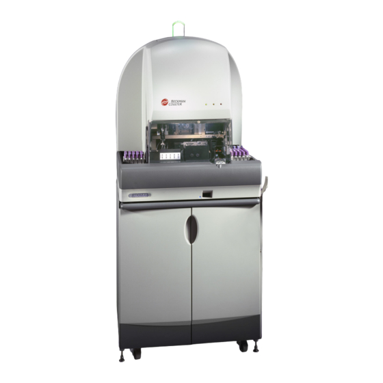
System Overview UniCel DxH 800 SYSTEM UniCel DxH 800 SYSTEM Figure 1.1 DxH 800 SYSTEM (SPM, PSM, and System Manager) ER ON PUM P RUN NIN PNE UMA PU LL FAU LT AD JU Component Function 1. Specimen Processing Module (SPM) Processes patient specimens and sends raw data to the System Manager. -
Page 38: Hardware
Figure 1.2 Power Connection Figure 1.3 shows the inter-unit connections of the power and signal cables that are supplied with the instrument. Your Beckman Coulter Representative makes these connections when installing the instrument. NOTE The colors used in Figure 1.3 are for illustration only, they are representative of the colors of the actual connections. -
Page 39: Interunit Power And Signal Cable Connections
Hardware Figure 1.3 Interunit Power and Signal Cable Connections Assembly No. Serial No. xxxxxx DxH 800 ANALYZER VOLTS 100-240 AMPS 8.0-2.8 Beckman Coulter, Inc. 4300 N. Harbor Blvd. 48-62 WATTS Fullerton, CA 92835 USA VACUUM RETIC DIFF NBBC WASTE 1... -
Page 40: Spm Consumable Connections
Supplies Screen. Refer to Replacing Reagents for information on replacing the reagents. Figure 1.4 SPM Consumable Connections Assembly No. Serial No. xxxxxx 100-240 8.0-2.8 DxH 800 ANALYZER VOLTS AMPS Beckman Coulter, Inc. 4300 N. Harbor Blvd. 48-62 WATTS Fullerton, CA 92835 USA VACUUM RETIC DIFF NBBC WASTE 1... -
Page 41: Front View Of The Spm
System Overview Hardware Front View of the SPM Figure 1.5 Front View of SPM The components called out in the figure above are as follows: 1. Beacon The light at the top of the SPM is a Beacon to visually alert you to conditions that require attention. -
Page 42: Specimen Transport Module
System Overview Hardware Specimen Transport Module The STM automatically transports specimens. It delivers closed-vial and open-vial specimens accommodating a wide range of specimen tubes. The STM supports the following: • Operator loading and unloading of specimens • Transport and queuing of specimens •... -
Page 43: Input Buffer
System Overview Hardware Input Buffer The input buffer is where you place specimen cassettes. The capacity is 20 cassettes. The STM magnetically sweeps the cassettes forward for transport to the mixing station. Single-tube Station with Cradle The Single-tube Station cradle accepts many sizes of tubes. -
Page 44: Output Buffer
System Overview Hardware Output Buffer Upon completion of their operation, cassettes are transported to the output buffer to await their removal. The output buffer is an output area capable of holding up to 20 cassettes. Sample Aspiration Module The SAM aspirates from capped specimen tubes (presented via Cassette or Single-tube presentation) or open vials (Single-tube presentation). -
Page 45: Bar-Code Reader
System Overview Hardware Bar-code Reader The 2D compatible digital barcode reader (camera) does the following: • Provides for positive identification for all specimen tube IDs in the form of an image. • Reads the cassette and specimen IDs twice prior to aspiration. Each read includes a minimum of 10 passes. -
Page 46: Pneumatic Supply Module (Psm)
System Overview Optional Floor Stand Pneumatic Supply Module (PSM) The Pneumatic Supply Module (PSM) is the source of vacuum and pressure to Common Services. Figure 1.8 Pneumatic Supply Module PO WE R ON PU MP P U L L RU NN PN EU IN G MA TIC... -
Page 47: Location Of Items In The Floor Stand
System Overview Optional Floor Stand The Floor Stand, Figure 1.9, provides self-contained support for the SPM as well as easy access storage for reagents and waste containers. Additionally, the Floor Stand houses the Pneumatic Supply on an integrated pull-out shelf. in the left lower section of the cabinet. Reagents are placed on slide-out drawers. - Page 48 System Overview Optional Floor Stand Accessing Items Contained in the Floor Stand Open the floor stand doors. Pull out the top left or right drawer to access reagents. 1-14 629743AE...
- Page 49 System Overview Optional Floor Stand In the top right drawer, Diluent 1 is located in the back and Diluent 2 is at the front of the drawer. Pull out the bottom right drawer to access the waste containers. Waste 1 is located in the back and Waste 2 is at the front of the drawer.
- Page 50 System Overview Optional Floor Stand Unlock the latches on the bottom left drawer to pull out the pneumatics drawer and access the Pneumatic Supply Module (PSM). . Lock the latches at the bottom of the left drawer when the drawer is closed. 1-16 629743AE...
-
Page 51: System Manager Indicators
System Manager Indicators The System Manager features touch screen capability that allows you to tap the Status icons and Menu buttons on the screen. Figure 1.11 System Manager Menu Tree Menu Patient Daily System Pending Summary Dx Tools Maintenance Results Checks System Add Order... -
Page 52: Home Screen
System Overview System Manager Indicators Home Screen The Home screen is the default startup screen of the System Manager. Figure 1.12 Home Screen at Log On The sections of the Home screen that are called out in the figure above are as follows: 1. -
Page 53: Global Menu Button
System Overview System Manager Indicators Global Menu Button The global button allows you to navigate through the system. Select to display available Menu Menu application buttons. Select any application button to display the screen for the selected functionality. Displays the Patient Results screen in dynamic mode Displays the System Status screen. -
Page 54: Qa Menu Selections
System Overview System Manager Indicators Figure 1.13 QA Menu Selections Figure 1.14 Diagnostics Menu Selections Figure 1.15 Setup Menu Selections Figure 1.16 Advance Menu Selections 1. Windows Explorer displays the My Computer window. 2. Fast User Switching allows the current user to log out of the operating system software. -
Page 55: Global Icons And Navigation/Status Buttons
System Overview System Manager Indicators Global Icons and Navigation/Status Buttons Previous/Next Icons icons at the top-left corner of any screen allow you to go back or Previous Screen/Next Screen forward a maximum of five times. The screen content from previously viewed screens will be relative to recent information. -
Page 56: Status Bar
System Overview System Manager Indicators Status Bar The Status Bar, at the bottom of every screen, displays the following: • Last event message (left side of the bar) • Operator ID of the logged on operator (middle of the bar) •... -
Page 57: Utility Icons
System Overview System Manager Indicators Supplies Indicates the status of the supply level. Select this icon to display the Supplies screen. Event Log Indicates the status of the General Tab in the Event Log. Select this icon to display the History Logs screen. Utility Icons The Utility icons always display in the top right-hand corner of the screen and include the following:... -
Page 58: System Icons
System Overview System Manager Indicators System Icons The System icons always display at the top of the screen just under the Utility icons and include the following: Start Places the SPM online for processing. Stop Places the SPM offline and stops processing. Turn Off Alarm Turns off the audible alarm when it is triggered. -
Page 59: Consumables And Supplies
System Overview Consumables and Supplies Consumables and Supplies Recommended Reagents COULTER® DxH Diluent COULTER DxH Diluent is a cyanide-free, isotonic buffered saline solution. COULTER DxH Diluent dilutes the specimen, is used for rinsing SPM components between sample analyses, and provides a sheath stream to transport the sample through the flow cell. -
Page 60: Material Safety Data Sheets (Msds)
System Overview Consumables and Supplies Material Safety Data Sheets (MSDS) To obtain an MSDS for Beckman Coulter reagents used on the DxH 800, go to www.beckmancoulter.com or in the USA, write to: Beckman Coulter, Inc. Attn: MSDS Requests P.O. Box 169015 Miami, FL 33116-9015 Outside the USA, contact your Beckman Coulter Representative. -
Page 61: Cassettes
System Overview Consumables and Supplies Cassettes 7-13mm 12-16mm 0 0 0 4 1 0 0 0 4 1 0 0 0 4 2 0 0 0 4 2 00041 00042 00043 00044 00045 0 0 0 4 3 0 0 0 4 3 0 0 0 4 4 0 0 0 4 4 0 0 0 4 5... -
Page 62: Physical Specifications
System Overview Physical Specifications Physical Specifications SPM Temperature and Humidity Specifications Temperature The SPM configured with DxH consumables will meet performance requirements at a temperature of +15.5°C to 32°C or 60°F to 90°F. Humidity The DxH 800 System operates at the following relative humidity (non-condensing) and temperature limits: •... -
Page 63: Installation Category
System Overview Physical Specifications Installation Category The SPM is in Installation Category II. Pollution Degree The pollution degree of the SPM is 2. Acoustic Noise Level Measure Level 60dBa or less. Dimensions (Depth, Width, Height) and Weight Depth Width Height Weight 31.0 inches 30.0 inches... -
Page 64: Space And Accessibility Requirements
System Overview Physical Specifications Space and Accessibility Requirements IMPORTANT The DxH 800 meets the immunity requirements for RF and other interference from electronic devices as required by the product level standards EN 61326-1 (Electrical Equipment for Measurement, Control, and Laboratory Use -EMC Requirements), and EN61326-2-6 (Part 2, specific requirements for In- vitro Diagnostic Devices).”... -
Page 65: Software Specifications
System Overview Physical Specifications Figure 1.18 Space and Accessibility Requirements for the DxH 800 with the Optional Floor Stand 21 .6 cm (8 .5 in .) 1 0 4 .1 c m (4 1 .0 in .) 1 5 . 2 i n . -
Page 66: Performance Specifications And Characteristics
All performance claims in this manual are based on data from specimens collected into the anticoagulants indicated below. CAUTION These anticoagulants are recommended by Beckman Coulter. Use of other anticoagulants may yield misleading results. CAUTION Follow the tube manufacturer’s recommended procedure for the correct specimen collection. -
Page 67: Accuracy
System Overview Performance Specifications and Characteristics Accuracy Whole Blood - CBC Accuracy for the CBC parameters is assessed by comparison of the results from the DxH 800 and a comparative method. The estimation of the difference is determined as described in CLSI EP09-A2 Method Comparison and Bias Estimation Using Patient Samples. -
Page 68: Accuracy Specifications (Dxh Vs. Manual Diff), Whole Blood - Differential - Clsi H2O-A2
System Overview Performance Specifications and Characteristics Differential Accuracy for the Differential parameters is assessed by comparison of the results from the DxH 800 and a comparative method. Results may be compared to either an automated hematology analyzer or to a 400 cell manual differential prepared according to CLSI H20-A2 Reference Leukocyte (WBC) Differential Count (Proportional) and Evaluation of Instrumental Methods (H20). -
Page 69: Nrbc
System Overview Performance Specifications and Characteristics Reticulocyte Accuracy for the Reticulocyte parameters is assessed by comparison of results from the DxH 800 and a predicate instrument. Estimation of difference is determined using CLSI EP09-A2. The DxH 800 meets specification if results meet the limits defined in the table below. Table 1.4 Accuracy Specification, Whole Blood - Reticulocytes Parameter Units... -
Page 70: Repeatability
System Overview Performance Specifications and Characteristics Repeatability Table 1.7 Repeatability - Whole Blood CBC, DIFF, Retic (N=10) Parameter Units Range Limit ≤5.0% CV 0.500−2.000 /μL ≤3.0% CV 5.000–10.000 ≤1.5% CV 4.5 to 5.5 /μL ≤1.5% CV g/dL 14 to 16 ≤1.0% CV 80 to 90 ≤2.5% CV... -
Page 71: Measuring And Operating Ranges
System Overview Performance Specifications and Characteristics Table 1.8 Repeatability - Prediluted Blood (N=10) Parameter Units Range Limit ≤6.0% CV 5.000–10.000 /μL ≤3.0% CV 4.5 to 5.5 /μL ≤3.0% CV g/dL 14 to 16 ≤7.0% CV 200 to 400 /μL Table 1.9 Repeatability - CSF, Serous or Synovial Body Fluid Count (N=10) Parameter Unit Repeatability... -
Page 72: Nrbc1
System Overview Performance Specifications and Characteristics Table 1.10 Whole Blood Measuring and Operating Ranges Parameter Units Measuring Range Operating Range Linearity (r UWBC * 0.000–400.000 0.000–999.999 /μL >0.95 WBC * 0.000–400.000 0.000–999.999 /μL >0.95 0.000–8.500 0.000–10.000 /μL >0.95 g/dL 0.00–25.50 0.00–30.00 0.00–70.00 50.00–150.00... -
Page 73: Carryover
0–600,000 cells/mm Beckman Coulter recommends that a diluent be run as a Body Fluid sample prior to analysis of Body Fluid specimens. Backgrounds within specifications can influence the reported results on the samples with low abnormal or normal values. Beckman Coulter recommends that each laboratory establish criteria for evaluation of the impact on the background on the reported results. -
Page 74: Background Counts
System Overview Performance Specifications and Characteristics Background Counts The following tables list the acceptable background limits for Daily Checks and Body Fluids. Table 1.13 Background - Daily Checks Parameter Limit ≤0.05 x 10 /μL ≤0.005 x 10 /μL ≤0.1 g/dL ≤3 x 10 /μL ≤10 events... -
Page 75: Reference Range Studies
System Overview Performance Specifications and Characteristics Reference Range Studies A Normal Range study was conducted to assess the Reference Ranges for the DxH 800. Whole-blood samples were collected from approximately 240 donors (males and females). The selection of donors was consistent with guidelines stated in CLSI, C28-A2. These ranges are used as the System Manager default normal range flags. -
Page 76: Whole Blood Reference Ranges Male
System Overview Performance Specifications and Characteristics Table 1.17 Whole Blood Reference Ranges Male Parameter Units Male Mean 95% Confidence 95% Confidence Low Limit High Limit 10.2 /μl 4.81 4.06 5.63 /μl g/dl 14.2 12.5 16.3 41.3 36.7 47.1 86.1 73.0 96.2 29.6 23.8... -
Page 77: Whole Blood Reference Ranges Female
System Overview Performance Specifications and Characteristics Table 1.18 Whole Blood Reference Ranges Female Parameter Units Female Mean 95% Confidence 95% Confidence Low Limit High Limit 11.8 /μl 4.26 3.63 4.92 /μl g/dl 12.6 10.9 14.3 36.9 31.2 41.9 86.8 75.5 95.3 29.6 24.7... -
Page 78: Body Fluids Reference Ranges
System Overview Performance Specifications and Characteristics Body Fluids Reference Ranges Reportable body fluid results obtained from the DxH 800 System may exceed commonly accepted normal reference ranges for all body fluids. Results should always be interpreted in light of the total clinical presentation of the patient, including clinical history, data from additional tests, and other appropriate information. -
Page 79: Sample Stability And Storage
The difference in mean results will be within the stability ranges defined in Table 1.19 and 1.20. Beckman Coulter recommends analyzing all non-refrigerated whole blood samples within 24 hours. 629743AE 1-45... -
Page 80: Sample Stability (Whole Blood)
System Overview Performance Specifications and Characteristics Whole Blood Long term stability is determined by comparing results from the initial analysis (within two hours of collection) to results from samples stored at controlled room temperature for 24 hours and refrigerated temperature for 48 hours. Upon removal from refrigerated storage, samples were hand mixed by inversion 20 times, allowed to warm at room temperature for a minimum of 30 minutes and then hand mixed by inversion 20 times prior to analysis. -
Page 81: Clinical Sensitivity And Specificity Performance Characteristics
Flags and Messages to meet individual laboratory requirements. Beckman Coulter, Inc. recommends completion of sensitivity and specificity studies using your sample population to establish these settings. Specimen Tubes The DxH 800 is capable of processing a wide variety of specimen tubes. -
Page 82: Venous And Capillary Sample Performance Characteristics
Performance Specifications and Characteristics Venous and Capillary Sample Performance Characteristics Twenty-nine specimens from normal Beckman Coulter in-house donors were collected as whole blood venous and whole blood capillary specimens. When analyzed on the DxH 800, a number of specimens did not provide parameter results and were excluded from the analysis. The results of the study are shown below. -
Page 83: Closed And Open Vial Performance Characteristics
Performance Specifications and Characteristics Closed and Open Vial Performance Characteristics Twenty-five specimens from normal Beckman Coulter in-house donors were collected and analyzed as closed vial and open vial specimens. The results of the study are shown below. Table 1.22 Closed and Open Vial Performance Characteristics... -
Page 84: Whole Blood And Pre-Dilute Performance Characteristics
System Overview Performance Specifications and Characteristics Whole Blood and Pre-Dilute Performance Characteristics Fifty-seven specimens were analyzed as whole blood and pre-dilute. The results of the study are shown below. Table 1.23 Whole Blood and Pre-Dilute Performance Characteristics Mean Parameter Correlation Intercept Slope Whole Pre- Units... -
Page 85: Limitations
All Specimens Misleading results can occur if the specimen is not properly collected, stored or transported. Beckman Coulter, Inc. recommends that you follow CLSI or equivalent procedures to ensure proper specimen collection, storage and transport. Always follow manufacturer’s recommendations when using microcollection devices for capillary specimen collection. - Page 86 System Overview Performance Specifications and Characteristics Differential Hypogranular granulocytes, agranular granulocytes, lyse resistant red cells, very small or multi-population lymphocytes, elevated triglycerides, precipitated elevated proteins. A transient basophilia may be observed in samples that have been exposed to high temperatures (~ 90°F or ~ 32°C). The temporary basophilia should resolve after stabilization at room temperature (~ 72°F or ~ 22°C).
-
Page 87: Operation Principles
CHAPTER 2 Operation Principles History Coulter Principle W.H. Coulter (1956) describes the Coulter Principle: A suspension of blood cells is passed thru [sic] a small orifice simultaneously with an electric current. The individual blood cells passing through the orifice introduce an impedance change in the orifice determined by the size of the cell. -
Page 88: Coulter Method
Operation Principles History Coulter Method The Coulter Method accurately counts and sizes cells by detecting and measuring changes in electrical resistance when a particle (such as a cell) in a conductive liquid passes through a small aperture. See Figure 2.1, Coulter Method. -
Page 89: Ttm
Historically, Beckman Coulter analyzers housed a flow cell in a Triple Transducer Module (TTM), first introduced commercially in the 1980’s. The TTM flow cell was the location for detection of the processed samples. -
Page 90: Dxh 800 Operation Principles
Operation Principles DxH 800 Operation Principles DxH 800 Operation Principles CBC Analysis In hematology, the complete blood count, the CBC, is the fundamental analytical test that evaluates the three main cellular components: white blood cells, red blood cells and platelets. The DxH 800 CBC analysis is based on the Coulter Principle. -
Page 91: Detection/Sensing
Operation Principles DxH 800 Operation Principles Detection/Sensing After the mixing and incubation of sample and reagents, 6 inches of vacuum and aperture current are applied to the apertures simultaneously for the measurements of cell count and cell volume. The RBC and PLT count includes the application of sweep flow to prevent the recirculation of cells behind the aperture. - Page 92 Operation Principles DxH 800 Operation Principles Figure 2.3 Sweep Flow Example A: No Sweep Flow Example B: Sweep Flow Added 1. Sensing Zone 1. Sensing Zone 2. Cell Recirculates 2. Cell Carried to Waste 3. Sweep Flow Counting/Sizing The RBC and WBC baths each have three discrete apertures that function as independent systems, utilizing the Coulter Method to accurately count and size cells.
-
Page 93: Hemoglobinometry
Operation Principles DxH 800 Operation Principles Hemoglobinometry The lytic reagent used for the WBC prepares the blood so the system can count leukocytes and measure the amount of hemoglobin. The lytic reagent rapidly and simultaneously destroys the erythrocytes and converts a substantial proportion of the hemoglobin to a stable pigment while it leaves leukocyte nuclei intact. -
Page 94: Vcsn
Operation Principles VCSn VCSn All Diff, NRBC, and Retic analysis occurs in the VCSn module. The VCSn module is responsible for controlled sample preparation and delivery of the prepared sample to the flow cell for analysis of the WBC differential, reticulocytes and NRBC. The VCSn module includes the Air Mix and Temperature Control (AMTC) Module and the Multi-transducer Module (MTM). -
Page 95: Volume And Conductivity
Operation Principles VCSn Figure 2.4 Multi-Transducer Module with Protective Housing Cut Away AVOID EXPOSURE AVOID EXPOSURE LASER RADIATION IS LASER RADIATION IS EMITTED FROM THIS APERTURE EMITTED FROM THIS APERTURE AVOID EXPOSURE TO BEAM AVOID EXPOSURE TO BEAM CLASS 3B LASER EMISSION CLASS 3B LASER PRODUCT IEC 60825-1 :2001-8 IEC 60825-1... -
Page 96: Light Scatter On The Dxh
Operation Principles VCSn Figure 2.5 Light Scatter on the DxH 800 1. Lower Electrode (DC and RF) 2. Upper Electrode (DC and RF) 3. Axial Light Loss (ALL) 0° 4. Low Angle Light Scatter (LALS) 5.1° 5. Lower Median Angle Light Scatter (LMALS) 10°–20° 6. -
Page 97: Dataplot Development
Operation Principles VCSn Dataplot Development The System Manager performs a series of operations on the stored digital raw values received from the flow cell to identify populations and calculate the frequency of cells within each population. The system produces the Dataplot displays for visual representation of the Differential, NRBC and Reticulocyte membership and density. -
Page 98: Two-Dimensional (2-D) Dataplots
Operation Principles VCSn Two-Dimensional (2-D) Dataplots DIFF The 2-D, 5 Part Diff (5PD) Dataplot shows the five main populations: lymphocytes (LY), monocytes (MO), neutrophils (NE), eosinophils (EO) and basophils (BA), plus the non-white cell populations. For the 5PD1 Dataplot, Volume (V), is plotted on the Y-axis; Rotated Light Scatter (RLSn) is plotted on the X-axis. -
Page 99: Surface Plots
Operation Principles VCSn Surface Plots Surface plots (See Figure 6.20) show the same populations as the 2-D Dataplots, with the addition of density in the Z direction (for example, peak height): 5PD1 - RLSn (X) versus V (Y) 5PD2 - OP (X) versus V (Y) NRBC1 - AL2 (X) versus RLALS (Y) NRBC2 - AL2 (X) versus RUMALS (Y) RETIC1 - LLSn (X) versus V (Y) -
Page 100: Parameter Measurement, Derivation, And Calculation
Operation Principles Parameter Measurement, Derivation, and Calculation Parameter Measurement, Derivation, and Calculation Table 2.1 Parameters and their Derivation Parameter Method Description (Reporting Units in US-1 Format) Coulter Principle White Blood Cell Count or Leukocyte Count • Measured directly, multiplied by the calibration factor. •... -
Page 101: Parameters And Their Derivation
Operation Principles Parameter Measurement, Derivation, and Calculation Table 2.1 Parameters and their Derivation Parameter Method Description (Reporting Units in US-1 Format) Calculated Mean Corpuscular Hemoglobin • The weight of Hgb in the average erythrocyte • MCH (pg) = (Hgb/RBC) x 10 MCHC Calculated Mean Corpuscular Hemoglobin Concentration... - Page 102 Operation Principles Parameter Measurement, Derivation, and Calculation Table 2.1 Parameters and their Derivation Parameter Method Description (Reporting Units in US-1 Format) NRBC VCSn Technology Nucleated Red Blood Cell Count • The number of nucleated red blood cells (NRBC) per 100 WBC •...
-
Page 103: Quality Control Principles
Operation Principles Quality Control Principles Quality Control Principles Overview The purpose of Quality Control is to monitor various aspects of the SPM’s performance. Quality Assurance includes service and maintenance as required in conjunction with the use of controls and calibrators. The combination of these methods provides the assurance of complete quality control and should be applied separately or in combination, in accordance with your laboratory and accreditation requirements. -
Page 104: Iqap
IQAP allows you to submit your control recovery data to Beckman Coulter and in return, receive a personalized report that summarizes your results and compares them to those of your peer group (pool). -
Page 105: Daily Checks
CHAPTER 3 Daily Checks Daily Checks ( > > Menu Daily Checks Daily Checks ensure that your DxH 800 System is running correctly. NOTE For information on Quality Control that you can perform in addition to Daily Checks, refer to the Quality Control chapter. -
Page 106: Run Daily Checks
Daily Checks Daily Checks (Menu > QA > Daily Checks) Run Daily Checks Select the button from the top of any screen to display the Daily Checks- Summary Daily Checks screen with results of the most recent Daily Checks. Figure 3.1 Daily Checks - Summary Screen Select the button at the bottom of the screen. -
Page 107: Daily Checks Screen
Daily Checks Daily Checks (Menu > QA > Daily Checks) Daily Checks Screen The results of Daily Checks display on eight tabbed views: Summary (default view), System, Background, Supplies, CBC, Diff, Retic, NRBC. When Daily Checks pass, the icon is Daily Checks neutral. - Page 108 Daily Checks Daily Checks (Menu > QA > Daily Checks) The button options on the Local Navigation bar at the bottom of the Daily Checks screen are described below. Button Function Daily Checks Runs Daily Checks Shutdown Shuts down the SPM. Auto Report Allows you to configure auto reporting for Daily Checks.
-
Page 109: Diff, Retic, And Nrbc
Daily Checks Daily Checks (Menu > QA > Daily Checks) DIFF, RETIC, and NRBC Select the button at the right of the screen on the DIFF, RETIC or NRBC tabs to display Histograms the VCSn Ramp Tests Histogram screen. Figure 3.3 Daily Checks - NRBC Screen 629743AE... -
Page 110: Vcsn Ramp Tests Histograms Screen
Figure 3.4 VCSn Ramp Tests Histograms Screen NOTE The VCSn Ramp Tests Histogram screen is not for routine use; however, you may at some time be asked to access this screen when on the phone with your Beckman Coulter Representative. 629743AE... -
Page 111: Export Daily Checks
Daily Checks Export Daily Checks Export Daily Checks Select the button on the Local Navigation Bar to export Daily Checks results to a raw data file Export (INF/DAT) or a .csv file. Figure 3.5 Export QA Data Dialog Box Select the of file. -
Page 112: Print Daily Checks
Daily Checks Print Daily Checks Print Daily Checks Select the icon at the top of the Daily Checks screen to manually print Daily Checks Summary Print or Detail reports. 629743AE... -
Page 113: Quality Control
The DxH 800 System allows you to use multiple quality control techniques that are outlined in this chapter. Beckman Coulter recommends that Quality Control checks be performed using patient or commercial controls by either cassette or single-tube presentation at intervals established by your lab. -
Page 114: When A Commercial Control Is Outside Its Expected Range
3. Ensure the flow cell is clear by performing the Flush Flow Cell procedure. 4. Rerun the control. If the control is still outside the expected ranges, call your Beckman Coulter Representative. You can set the SPM to CBC mode and continue to process CBC samples. -
Page 115: Analyze Commercial Controls
Quality Control Overview Analyze Commercial Controls Prepare the control according to the instructions on the package insert. Follow the instructions in your package insert for running the control. Viewing Control Files - Data View ( > > Menu To view control files on the Quality Control (Data View) screen: Select the icon at the top of any screen to display the Quality Control screen. -
Page 116: Quality Control (Data View) Screen With Extended Qc Enabled
Quality Control Overview Figure 4.2 Quality Control (Data View) Screen with Extended QC Enabled The Quality Control - Data View screen displays the most recently analyzed control lot with the most recently analyzed run selected by default. If controls have not been reviewed, a dialog box displays a list of those controls that have not been reviewed. - Page 117 The target used for Extended QC will be based on what has been configured for Traditional QC (either assigned or Mean to Target values). If Beckman Coulter or manually-entered targets are used, then the label below this (Assigned or heading reads “Assigned”;...
-
Page 118: Options On The Local Navigation Bar On The Quality Control Screen
Quality Control Overview Comment A comment icon displays in this column if any comments have been added. Ref. RBC If the control type is a RETIC only, a REF. RBC heading and numeric value display on the left side of the screen under the Summary Data columns. If the control is RETIC only and the Reference RBC Target and Limit are not set, No Value will display in the Ref. -
Page 119: Select A Control
Quality Control Overview Select a Control From the Quality Control (Data View) screen or the Quality Control (Graph View) screen, select button on the Local Navigation Bar to display the QC Select Controls dialog Select Control box. Figure 4.3 QC Select Controls Dialog Box Select a control and select the button. -
Page 120: View Control Files Graphically (Menu > Qa > Qc > View Graph)
Quality Control Overview View Control Files Graphically ( > > > Menu View Graph From the Quality Control - Data View screen, select the button. View Graph Select a parameter (row) and double tap the Thumbnail Levey-Jennings graph. Figure 4.4 Quality Control (Graph View) Screen The Quality Control (Graph View) screen displays the following: •... -
Page 121: Thumbnail Levey-Jennings Graph
Quality Control Overview Thumbnail Levey-Jennings Graph The top half of the Quality Control (Graph View) screen displays all parameters associated with controls. Up to 31 Thumbnail Levey-Jennings graphs display the latest run points for all parameters. Each graph displays up to 10 points and these points change to reflect the scrolling of the expanded graph. -
Page 122: View Logs
Quality Control Overview 2. Points above or below the y-axis scale display as a red up-triangle or red down-triangle, respectively. 3. Out conditions display as red points. 4. Excluded points display with a strike through them. 5. Points with Extended QC Single Measurement Error display in yellow. 6. -
Page 123: View Details Of A Control Run
Quality Control Overview View Details of a Control Run You can view control run details on the QC Run Details screen. From the Quality Control - Data View screen, select a run and then select the button. Details From the Quality Control (Graph View), select the button. - Page 124 Quality Control Overview The components on the QC Run Details screen are described below. Component Description Control ID Read-only field that displays the Control ID. Source Read-only field that displays the control source Type Read-only field that displays the control type. Level Read-only field that displays the control level.
- Page 125 Quality Control Overview Component Description Dataplots One 2-D dataplot displays. The type and tabs displayed on the dataplot depend on the control type. A maximum of three tabs can display on one dataplot at one time. If a type of analysis is disabled, then the corresponding dataplot does not display, and as a result, the tab does not display as well.
-
Page 126: View Additional Data
Quality Control Overview View Additional Data The Additional Data dialog box allows you to view additional data for a control run: From the QC Run Details screen, select the button to display the Additional Data Additional Data dialog box. Figure 4.6 Additional Data Dialog Box The Additional Data dialog box displays four tabbed views: CBC, DIFF, NRBC, and RETIC. -
Page 127: Add, Modify, Or Delete Comments
Quality Control Overview Add, Modify, or Delete Comments You can add, modify or delete comments to control file records. From the Quality Control (Data View) or Quality Control (Graph View) screen, select the button to display the QC Comment dialog box. Comment Figure 4.7 QC Comment Dialog Box The creation date/time, last modified date/time, and last modified Operator ID will not be... -
Page 128: Filter The View
Quality Control Overview Filter the View You can filter the view on the Quality Control (Data View) screen and the Quality Control (Graph View) screen using the following criteria: • All QC results within a number of days prior to and including the present day (Past Days) •... - Page 129 Quality Control Overview In the box, select one of the filter option buttons:. Choose Range - to view all the results - to view results from a specific number of past days. Past 1) Type a number in the text box. Past Days Specify Date and Time Range 1) Type or select a...
-
Page 130: Delete Control File Records
Quality Control Overview Delete Control File Records You can delete control file records from the Quality Control (Data View) screen. Select a run to delete and select the button. The Delete dialog box displays. Delete Figure 4.9 Delete Dialog Box Select one of the following option buttons: - to delete the selected run. -
Page 131: Transmit Control Files
Quality Control Overview Transmit Control Files You can transmit control files to a Laboratory Information System (LIS). From the Quality Control (Data View) screen, select the run that you want to transmit and select button. The Transmit dialog box displays. Transmit Figure 4.10 Transmit Dialog Box Select one of the following option buttons:... -
Page 132: View Control Files Under Error Conditions
Quality Control Overview View Control Files Under Error Conditions Under error conditions the Quality Control Status icon at the top of the screen is red. If more than one lot triggered an error condition, the Select Control File to Review dialog box displays. All lots that are OUT are displayed on the dialog box. -
Page 133: Export Quality Control Data (Menu > Qa > Qc > More Options > Export)
Quality Control Overview Export Quality Control Data ( > > Menu More Options Export > > Figure 4.12 Export Quality Control Dialog Box Select a from the drop-down list. Format Type In the option box, select the data to export. Data Selection Select a Destination... -
Page 134: Reports
Quality Control Reports Reports Types You can manually print the following types of reports from the Quality Control screen: • Run Details Report • Summary Report • Extended QC Summary Report (If Extended QC is enabled.) APPENDIX D for examples of reports. Printing Select the icon at the top of the Quality Control screen to display the QC Report dialog box. - Page 135 Quality Control Reports Select one of the following option buttons from the option box: Print - to print the selected run only • Selected Run - to print only the runs displayed in the current filtered view • All (Filtered Runs) - to print all runs in the file selected •...
-
Page 136: Xb Information
Quality Control XB Information XB Information Select Menu > QA > XB or the XB icon at the top of any screen in order to display the XB Review screen. If the alert status icon was red, the screen will default to the application that contains XB or XM Out results (whichever is enabled). -
Page 137: Xb Batch Means (Data View) Screen
Quality Control XB Information Figure 4.14 XB Batch Means (Data View) Screen The XB Batch Means screen combines statistics data and thumbnail Levey-Jennings graphs for MCV, MCH, and MCHC for all completed XB batches. Out of range batch means and percent differences for MCV, MCH and MCHC display in red. - Page 138 Quality Control XB Information The XB Batch Means (Data View) screen columns are defined below. Batch Date/Time Displays the batch completion date and time. If the batch out condition triggers an XB/XM icon alert (red), the Batch Date/Time displays in red. NOTE P indicates P.M.
-
Page 139: Xb Batch Details
Quality Control XB Information XB Batch Details Selecting the button on the XB Batch Means screen displays the XB Batch Details Batch Details screen of the batch selected from the XB Batch Means screen. Figure 4.15 XB Batch Details Screen Exclude From the screen, select the... -
Page 140: Graphics
Quality Control XB Information Graphics Thumbnail Levey-Jennings Graphs The XB Batch Means and XB Batch Details screens both display a thumbnail separate graph for MCV, MCH, and MCHC. Each thumbnail graph displays all result points (up to 20 points) in the batch. Point Cursor The point cursor is a blue vertical line on the graph that reflects the analysis date of the selected run in the date grid. -
Page 141: Add, Modify And Delete Comments
Quality Control XB Information Add, Modify and Delete Comments Select the Comments button to display the XB Comment dialog box. To modify or add a comment, type in the text box and select To delete a comment, select the button. Delete Figure 4.16 XB Comment Dialog Box Delete XB... -
Page 142: Printing Xb Batch Reports
Quality Control XB Information • XB Batch Means Report APPENDIX D for examples of reports. Printing XB Batch Reports Select the icon at the top of the XB review screens to display the Print XB Batch Reports Print dialog box. Figure 4.17 Print XB Batch Reports Dialog Box Select from the following options: •... -
Page 143: Export Xb
Quality Control XB Information Export XB You can export XB results to a CD-ROM or a local drive on the System Manager. The exported data is in a .csv format which can be read on any other computer that has a spreadsheet program. Select the button to display the XB Batch Export dialog box. -
Page 144: Xm Information
Quality Control XM Information XM Information Setup For instructions on setting up XM Quality Control, refer to the Quality Control (Menu > Setup > Quality Control) section of the Setup Chapter. Review (Menu > > Review the results of XM analysis from the XM Batch Means screen’s two views: Data View and Graph View or from the XM Batch Details screen. -
Page 145: View Subsets From The Xm Batch Means Screen
Quality Control XM Information View Subsets from the XM Batch Means Screen Figure 4.19 XM Batch Means (Data View) Screen NOTE When the XM Batch Means (Data View) screen initially displays, it defaults to the tab or group that has an Out condition. -
Page 146: Summary Statistics
Quality Control XM Information Batch/Date Time Displays the batch completion date and time for the batch. If the batch is Out, the Batch/Date Time displays in red. If the current batch has not completed, Current Batch will display in the Batch/Date Time column for that batch. -
Page 147: Mark As Reviewed
Quality Control XM Information Displays the high limit value for each High Limit parameter in a test group. Displays the low limit value for each Low Limit parameter in a test group. Mark as Reviewed To mark a batch as reviewed, select the Click to Review link that displays in the Reviewed By column for that batch to display the Review Batches dialog box. -
Page 148: Xm Graph View
Quality Control XM Information XM Graph View The XM Batch Means (Graph View) displays Levey-Jennings graphs for each test group or subset of the XM Analysis. To display the Graph View select the button from the XM Batch Means View Graph (Data View) screen. - Page 149 Quality Control XM Information A Levey-Jennings graph does not display for a test if any of the following conditions are met: • The limit is set as manual update and the target value exceeds the low and high limits. • The target value is equal to the low and high limits. •...
-
Page 150: View Xm Batch Details
Quality Control XM Information View XM Batch Details From the XM Batch Means screen, select a batch data row and then the button to Batch Details display the XM Batch Details screen. Use the scroll bar at the bottom of the screen to view all the data. -
Page 151: Delete Xm
Quality Control XM Information Type a comment in the text box and click to save the comment, Select to exit the dialog box without saving the comment. Cancel Modify XM Comments From the XM Batch Means (Data View) screen, select a batch with a Comment icon in the column and then select the button at the bottom of the screen. -
Page 152: Xm Reports
Quality Control XM Information XM Reports Types The following types of reports can be manually printed from the XM Review screens: • XM Batch Details Report • XM Batch Means Report • Levey-Jennings Graphs APPENDIX D for examples of reports. Printing Reports Select the global icon at the top of the XM Review screens to display the Print XM Batch... -
Page 153: Export
Quality Control XM Information Select from the following options: • XM Batch Details Report — Selected Batch — All Batches in Selected Group • XM Batch Means Report — — DIFF — RETIC — RETIC CALC — Levey-Jennings Graphs Select the button to print the selected reports. -
Page 154: Xm Batch Export Dialog Box
Quality Control XM Information Figure 4.24 XM Batch Export Dialog Box Select from the following options: • XM Batch Details Data — Selected — All Batches in Selected Group • • DIFF • RETIC • RETIC CALC Select the option if you want to export the data to a CD-ROM. CD Recorder NOTE This process may take several minutes. -
Page 155: Select Folder Dialog Box
Quality Control XM Information Figure 4.25 Select Folder Dialog Box 629743AE 4-43... - Page 156 Quality Control XM Information 4-44 629743AE...
-
Page 157: Sample Analysis
5,6,7 Collect whole blood in EDTA according to tube manufacturer’s instructions and procedures in: • CLSI publication H4-A5 (for capillary) • CLSI publication H3-A6 (for venipuncture) Beckman Coulter recommends using K or K EDTA. Body Fluids To reduce body fluid sample viscosity, use hyaluronidase to treat synovial fluids prior to analysis according to your laboratory standards. -
Page 158: Specimen Preparation (Pre-Dilute)
Sample Analysis Specimen Preparation (Pre-dilute) CAUTION If capillary tubes are used, they must be analyzed uncapped as open-vial samples. CAUTION Misleading results could occur if you fail to leave space at the top of the tube between the sample and the stopper. Ensure you leave space at the top of the tube between the sample and the stopper to facilitate automatic mixing. -
Page 159: Placing The Bar-Code Label On The Tube
Sample Analysis Placing the Bar-code Label on the Tube Placing the Bar-code Label on the Tube CAUTION Risk of misidentification. Use of poor quality, dirty, improperly placed or damaged bar-code labels could keep the SPM from reading the bar-code labels. Ensure the bar-code labels are not damaged. -
Page 160: Load Cassettes
Sample Analysis Load Cassettes Load Cassettes Cassette Handling The cassette is the carrier for the sample tubes (patient control, or special test) used in cassette presentation where automatic loading, mixing, and aspiration occurs. Tubes should be pushed into the cassette with the tube bar-code labels facing up. Always hold the cassette firmly by its edges. -
Page 161: Example Of Cassette With Tubes Loaded Correctly And
Sample Analysis Load Cassettes Figure 5.2 Example of Cassette with Tubes Loaded Correctly and Incorrectly 00041 00042 00043 00044 00045 In the figure above, 1 and 2 are examples of good placement, while examples 3 - 5 are examples of incorrect placement. -
Page 162: Add A Test Order
Sample Analysis Add a Test Order Add a Test Order You can add a test order by automatically downloading the order from the LIS or by manual entry. Automatic Download from LIS Refer to the Host Transmission Manual that came with your DxH 800 System as well as the Setup chapter of this manual for information on configuring download from the LIS. -
Page 163: Specimen Information Panel
Sample Analysis Add a Test Order Figure 5.4 Add Order Screen NOTE Use the tab button to move through the fields on the Add Order screen. Specimen Information Panel If the Primary Identifier is Specimen ID, type a and press Specimen ID If the Primary Identifier is Tube Position ID, type a and press... -
Page 164: Available Panels
Sample Analysis Add a Test Order • Ordering Physician Available Panels Verify the selected panel, or select a new and select to include it in the Available Panel list. Available panels vary depending on the Specimen Type selected. Refer to Selected Panels Table 5.1 for a list of available panels. -
Page 165: Patient Information Panel
Sample Analysis Add a Test Order Patient Information Panel To add Patient demographics to an order, type the in the panel Patient ID Patient Information and press to display the Find Patient dialog box. Figure 5.5 Find Patient Dialog Box Select to add the patient’s demographics to the order. -
Page 166: Add Order Comments (Pending Tab > Add Order > Comments)
Sample Analysis Add a Test Order : Allows you to enter the correct Patient ID (in case the Patient ID is wrong). • Rectify Patient ID Refer to Rectify Patient ID in the Setup chapter for additional information. Add Order Comments ( >... -
Page 167: Edit A Test Order (Worklist > Pending Tab > Edit Order)
Sample Analysis Add a Test Order Type a in the text box or select the button to add a System Comment System Comment Comment. NOTE If you type a comment here, that comment will be available for future selection in the list of System Comments. -
Page 168: Run Samples
Sample Analysis Run Samples Edit the information on the screen and select Submit Run Samples Status The SPM must be online to run samples. You can view the status of the SPM in the Status Mode area at the upper left hand corner of any screen. Cassette Presentation WARNING Risk of personal injury. - Page 169 Sample Analysis Run Samples Load the specimens into the cassettes. CAUTION Narrow tubes with small internal diameters will require manual premixing prior to analysis to ensure proper cell and plasma distribution and to avoid possible erroneous results. Premix these tubes before placing them in the cassette and then analyze the cassette by pacing it in the Stat position of the Input Buffer.
- Page 170 Sample Analysis Run Samples WARNING To avoid serious injury, do not place your hand through the cassette presentation opening on the SPM. After the SPM cycles the samples, review the sample results at the System Manager. Refer to Data Review chapter for information on reviewing sample results.
-
Page 171: Single-Tube Presentation
IMPORTANT Beckman Coulter recommends that a diluent be run as a Body Fluid sample prior to analysis of Body Fluid specimens to verify acceptable backgrounds. Ensure your specimens have been collected and stored properly. -
Page 172: Single-Tube Presentation Dialog Box
Sample Analysis Run Samples Figure 5.9 Single-tube Presentation Dialog Box Place the specimen on the bar-code reader platform of the Single-tube Presentation Station with the bar code facing the SPM to allow the Single-Tube Presentation Bar-code Reader to scan the specimen label. . Type the and press Specimen Identifier... - Page 173 Sample Analysis Run Samples Scan the bar code with the handheld scanner. Move the cursor to the end of the ID field by touching the end of the ID or using the mouse to click at the at the end of the ID. Then, press .
-
Page 174: Using The Handheld Scanner
Sample Analysis Run Samples CAUTION Do not place a closed tube or a 16 mm diameter tube in the right position of the Single-tube Presentation Station. Doing so could result in an incomplete aspiration and an erroneous result. Using the Handheld Scanner Your DxH 800 handheld scanner is a camera that takes a picture of the bar code. -
Page 175: Studies
Risk of sample misidentification. When using the handheld scanner, occasional misread errors can occur as a result of partial label scans and damaged or misapplied labels. Beckman Coulter recommends that you verify each bar-code reading to ensure correct patient identification. - Page 176 Sample Analysis Run Samples 5-20 629743AE...
-
Page 177: Data Review
CHAPTER 6 Data Review Worklist Screen The Worklist screen manages test orders and results within the database. The Worklist screen allows you to: • Use predefined filters for display and monitoring of patient test orders and results • Specify sort/filter criteria for display and monitoring of patient test orders and results •... - Page 178 Data Review Worklist Screen IMPORTANT The green Refresh icon at the top of the screen, shown in the figure below, indicates that you need to select the Refresh button on the Local Navigation bar at the bottom of the screen. For each tab: •...
-
Page 179: Pending Tab(Menu > Worklist > Pending Tab)
Data Review Worklist Screen Pending Tab( > > Menu Worklist Pending Tab Figure 6.1 Worklist -Pending Tab The Pending tab displays all patient test orders with a pending or partially complete result status (any result status that is not complete). The default sort order on the Pending tab for a new use session is listed below. - Page 180 Data Review Worklist Screen The Components on the Worklist- Pending screen are outlined below: Component Description Results Found Read-only field that displays the total number of results found for the tab. If no entries are found, this field displays 0 (zero). Specimen ID If Specimen ID is the selected primary identifier, then this is the specimen’s unique identifier.
-
Page 181: Remove Pending Orders
Data Review Worklist Screen Remove Pending Orders hides a pending order from view on the worklist tab, although it remains pending. You can Remove view Removed orders from the Custom tab by selecting the filter. Removed Figure 6.2 Remove Pending Orders Dialog Box Select the orders that you want to remove on the Remove pending orders dialog box and select 629743AE... -
Page 182: Delete Pending Orders
Data Review Worklist Screen Delete Pending Orders You can delete pending orders automatically or manually. Refer to Database Cleanup (Menu > Setup > System > Database Cleanup) in the Setup chapter for additional information on automatic deletion. To manually delete pending orders, select the button on the Navigation bar at the Delete Order bottom of the Worklist-Pending screen to delete selected orders from the database. -
Page 183: Not Processed Tab(Menu > Worklist > Not Processed Tab)
Data Review Worklist Screen Not Processed Tab( > > Menu Worklist Not Processed Tab The Worklist - Not Processed tab displays exceptions for specimens that have been skipped. You need to address the problem and reload the skipped specimens for processing. If exceptions are posted to the Not Processed tab, the alert status icon is red. -
Page 184: Clearing An Exception From The Not Processed Tab
Data Review Worklist Screen The components on the Worklist - Not Processed screen are outlined below: Component Description Results Found Read-only field that displays the total number of results found for the tab. Date Time of Event The date and time of the event that placed the skipped specimen into the Not Processed group. -
Page 185: Review Tab(Menu > Worklist > Review Tab)
Data Review Worklist Screen Select to clear the selected exceptions. Review Tab( > > Menu Worklist Review Tab The Worklist -Review tab displays specimens that have been held (not released) and require attention. Figure 6.6 Worklist - Review Tab Use the scroll bar to view all the components and data on this screen. The Filter at top right allows you to search by the following: •... - Page 186 Data Review Worklist Screen options on the Worklist-Review tab are outlined below: Component Function Specimen ID If Specimen ID is the selected primary identifier, then this is the specimen’s unique identifier. Tube Pos. ID If Tube Position ID is the selected primary identifier, then this is the specimen’s unique identifier.
-
Page 187: Released Tab(Menu > Worklist > Released Tab)
Data Review Worklist Screen Released Tab( > > Menu Worklist Released Tab The Worklist - Released tab displays the released results according to the filter that you select. Figure 6.7 Worklist - Released Tab The Filter Name drop-down list at the top right of the Released Tab allows you to filter by the following: •... - Page 188 Data Review Worklist Screen The components on the Released tab are described below. Component Function Specimen ID If Specimen ID is the selected primary identifier, then this is the specimen’s unique identifier. Tube Pos. ID If Tube Position ID is the selected primary identifier, then this is the specimen’s unique identifier.
-
Page 189: Transmit Released Results To The Lis
Data Review Worklist Screen Transmit Released Results to the LIS From the Worklist - Release Results screen, select the button to display the Transmit Transmit dialog box. Figure 6.8 Transmit Dialog Box Select from the following options in the Transmit option box: •... -
Page 190: Export Released Results (Released Tab > Export)
Data Review Worklist Screen Export Released Results ( > Released Tab Export Preparing .CSV creates two line items files available for import to a spreadsheet program (such as Microsoft Excel). Preparing INF/DAT files saves raw data offline. Figure 6.9 Export Dialog Box Select a type of file to export to: •... -
Page 191: Custom Tab(Menu > Worklist > Custom Tab)
Data Review Worklist Screen Custom Tab( > > Menu Worklist Custom Tab The Worklist - Custom tab allows you to select from predefined or user-defined filters. Figure 6.10 Worklist - Custom Tab Custom Tab Filter Select from the following options in the Filter Name drop-down list: •... - Page 192 Data Review Worklist Screen The components on the Custom tab are described below, Component Function Specimen ID If Specimen ID is the selected primary identifier, then this is the specimen’s unique identifier. Tube Pos. ID If Tube Position ID is the selected primary identifier, then this is the specimen’s unique identifier.
-
Page 193: How To Review Patient Results
Data Review How to Review Patient Results How to Review Patient Results To access the Patient Results screen, do one of the following: • Select Menu Patient Results > • Select a result, then select the button on the Worklist screen. Details a result twice on the Worklist screen. - Page 194 Data Review How to Review Patient Results • The area immediately to the right of the Tabs displays System Statuses, such as the Comment icon and “Specimen Deleted.” Also in this area, all the way to the right is the Patient Results Display Mode, which is either Dynamic or Filter.
-
Page 195: Dynamic Mode
Data Review How to Review Patient Results Component Description Release Selecting this button releases the patient result. Reject Selecting this button rejects the patient result. More Selecting this button displays the Rules Triggered button. If the specimen is collated, the View Source button displays. If the specimen is the source for a collated specimen, the View Collation button displays. -
Page 196: Static Mode
Data Review How to Review Patient Results Lock/Unlock the Screen To lock the screen, select the “unlocked” icon, as shown below, in the navigation panel on the Patient Results screen. To unlock the screen, select the “locked” icon. Static Mode The Patient Results screen is in Static Mode when the screen is accessed via the Details button on the Worklist screen. -
Page 197: Description Of Histogram/Dataplot Content On The Patient Results Screen
Data Review How to Review Patient Results Description of Histogram/Dataplot Content on the Patient Results Screen Histograms The main Patient Results screen displays WBC, RBC, and PLT histograms. For BFC panels, a TNC and RBC histogram are available.Double clicking or tapping a histogram pops up a larger view of the histograms. -
Page 198: Additional Data
Data Review How to Review Patient Results Dataplots A maximum of three tabs display dataplots, depending on the test order, according to the following rules: • If Diff was ordered, 5PD1 and NRBC1 tabs and dataplots display. • If Retic was ordered, a RETIC1 tab and dataplot displays. •... -
Page 199: Additional Data Cbc Tab
Data Review How to Review Patient Results Additional Data CBC Tab Select the CBC tab on the Additional Data screen to display additional CBC data. Figure 6.15 Additional Data - CBC Screen You can toggle the check box next to each Aperture to alternately display or remove the histogram data displayed for that Aperture. -
Page 200: Additional Data Diff Tab
Data Review How to Review Patient Results Additional Data DIFF Tab Select the DIFF tab on the Additional Data screen to display additional DIFF data. Figure 6.16 Additional Data -DIFF Tab 6-24 629743AE... -
Page 201: Additional Data Nrbc Tab
Data Review How to Review Patient Results Additional Data NRBC Tab Select the tab on the Additional Data screen to display additional NRBC data. NRBC Figure 6.17 Additional Data - NRBC Screen 629743AE 6-25... -
Page 202: Additional Data Retic Tab
Data Review How to Review Patient Results Additional Data RETIC Tab Select the tab on the Additional Data screen to display additional Retic data. Retic Figure 6.18 Additional Data - Retic Screen 6-26 629743AE... -
Page 203: View All Vcsn Graphics
Data Review How to Review Patient Results View All VCSn Graphics Histograms and 2-D Dataplots of the patient results display on the Patient Results screen. To view specific population and test panels as well as 3-D dataplots, select the View All VCSn Graphics button on the Patient Results screen. - Page 204 Data Review How to Review Patient Results The components on the View All VCSn Graphics dialog box are described below. Component Function Data Group Box Three radio buttons allow you to select data to view: DIFF, NRBC, or RETIC. Type Group Box Three radio buttons allow you to select which graphics to view: 2D dataplots, Surface Plots, or a 3-D Cube.
-
Page 205: Surface Plots
Data Review How to Review Patient Results If you selected , use the navigation buttons to Surface Plot 3-D Cube View Angle Analysis change your view of the graphic. NOTE Select the Circular Arrow button to rotate the graphic in a continuous circle. To stop the rotating graphic, select the Circular Arrow button again. -
Page 206: View Rules Triggered (Patient Results > More > Rules Triggered)
Data Review How to Review Patient Results Figure 6.21 3-D Cube View Rules Triggered ( > > Patient Results More Rules Triggered Figure 6.22 Rules Triggered Dialog Box 6-30 629743AE... -
Page 207: View Collation(Patient Results > More > View Collation)
Data Review How to Review Patient Results View Collation( > > Patient Results More View Collation Collation enables the addition of a Retic panel to a previously analyzed and released C or CD panel for a specific patient. The Retic panel order that is added must have the same Specimen ID and Patient ID of the specimen (C or CD) released. -
Page 208: View Source (Patient Results > More > View Source)
Data Review How to Review Patient Results View Source ( > > Patient Results More View Source If the current specimen is collated, select View Source to shift the current specimen being viewed to the specimen used as the source of the collation. From the collation source view of the Patient Results screen, select to return to the original collated specimen. -
Page 209: View Previous Or Next Patient Results
Data Review How to Review Patient Results View Previous or Next Patient Results You can view previous or next patient results from the Patient Results screen using the navigation buttons at the bottom right hand corner of the screen. Figure 6.25 Navigation Buttons on the Patient Results Screen 1. -
Page 210: View Rerun Tab
Data Review How to Review Patient Results View Rerun Tab A Rerun tab displays on the Patient Results screen if a Rerun has occurred. Figure 6.26 Patient Results - Rerun Tab On the Rerun tab: • Comments are indicated by the Comment icon at the top right of the Patient Results screen. •... -
Page 211: View History Tab
Data Review How to Review Patient Results View History Tab A History tab displays on the Patient Results screen if one or more released specimens are associated with a patient. Figure 6.27 Patient Results - History Tab On the History tab: •... -
Page 212: Reflex
Data Review How to Review Patient Results Reflex After reviewing patient results, you can run a test that you did not already order for a specimen, but would like to run based on the results, doctor’s orders, or decision rules. Running a test that has not already been ordered is called running a Reflex analysis. -
Page 213: Rerun
Data Review How to Review Patient Results Rerun After reviewing patient results, you can rerun a patient sample with the same ordered tests that were originally ordered. This type of analysis is called a Rerun. The Patient Results screen will display a tab when a Rerun is presented on the SPM. -
Page 214: Edit Patient Results
Data Review How to Review Patient Results Edit Patient Results NOTE The option to Edit is not available for Released Results. Results that cannot be edited on the Edit Patient Results dialog box are grayed out. Edited results are flagged with ‘E’. Results calculated from edited results are flagged ‘e’. From the Patient Results screen, select the button to display the Edit Patient Results dialog Edit... -
Page 215: Processing Results
Flags (including Delta Checks) and Decision Rules are not reevaluated upon a change of flagging limits for results already in the database. Beckman Coulter Inc. does not claim to identify every abnormality in all samples. Beckman Coulter suggests using all available options to optimize the sensitivity of instrument results. -
Page 216: Customization
CAUTION Refer to the Limitations section of the System Overview chapter for the interfering substances that might effect each parameter. Beckman Coulter recommends a slide review per your laboratory protocol. It is possible that the presence of a rare event cell can fail to trigger a suspect message. -
Page 217: Flags
Data Review Processing Results Flags Flags appear to the right of the result. For some parameters, flagging occurs as a result of the flagging or editing of other parameters. Flags in the following table are shown in order of placement on screens and printouts, with the highest priority flags at the top within each space. -
Page 218: Codes
Data Review Processing Results Codes Codes appear in place of results when the system cannot generate results. Codes are also called non-numeric results. Codes in the following table are shown in order of placement on screens and printouts, with the highest priority flags at the top within each space. -
Page 219: Messages That Appear With Results
Data Review Processing Results Messages that Appear with Results Several types of messages are generated on the UniCel DxH 800 along with specimen results: Suspect, System, Status, Definitive and Exception. The Suspect, System and Definitive messages display in the box just below the Susp/Sys/Def Msgs patient demographics at the top of the screen. - Page 220 Data Review Processing Results Suspect Message Description Abnormal Pattern characteristic of specimen with abnormal hemoglobin clearing Hemoglobin observed during retic analysis Cellular Inter Pattern consistent with NRBC detection during a CBC only cycle. This Cellular Interference Suspect message is not associated with a Review (R) flag. Dimorphic Reds Evidence of the presence of at least two populations of red cells Giant Platelets...
- Page 221 Data Review Processing Results System Message Description Abn WBC Pattern Undefined abnormal WBC pattern observed during any CBC analysis. Aged Sample Aged sample detected during Diff analysis. AL2 Blank Voltage: N AL2 blank voltages out of range during NRBC analysis. AL2 Blank Voltage: R AL2 blank voltages out of range during Retic analysis.
- Page 222 Data Review Processing Results System Message Description Low confidence in MPV, PDW, and PCT due to Low PLT count. Low Events: PLT Low OP Events Opacity mode location too low during Retic analysis. Low RMALS Events RMALS mode location too low during Diff analysis. MCV Inter: PLT Interference with MCV, RBC, and RDW and RDW-SD due to PLT.
-
Page 223: System
Data Review Processing Results System Message Description System Event: R Hardware parameters out of limit for some item that could affect Retic analysis (e.g. voltage, temperature, pressure). System Event: RBC Hardware parameters out of limit for some item that could affect RBC analysis (e.g. -
Page 224: Hgb/Hct Check
Data Review Processing Results HGB/HCT Check The H&H Check Failed is a Definitive Message that can be enabled using the H&H Check button on the Flagging Limits tab of the Flags Setup screen. Refer to the H&H Check (Menu > Setup > Flagging/ Rules >... -
Page 225: System Status Messages
Data Review Processing Results System Status Messages System status messages indicate that the instrument was operating in some non-standard state when a specimen was analyzed. These states are usually the result of some user action (e.g., operating with the cover opened). They do not indicate that any problem was seen when the specimen was analyzed;... -
Page 226: Exception Messages
Data Review Processing Results Exception Messages If there are any exceptions for a specimen, a comments indicator displays in the System Status Message area below the patient demographics. Select the button to view the Additional Data Exceptions. The only possible Exceptions for specimens' with results are those that indicate "No" below Specimen Skipped in the Exception list. -
Page 227: Lab Actions
Data Review Release/Reject Results Message Description Specimen Skipped Non-Studies Specimen A specimen with a matching patient test order was seen during Studies specimen processing. Inconsistent Flagging A flagging limit changed after analysis, even though the actual flags and messages generated for the results did not change. -
Page 228: Reject Results
Data Review Reject Results Select to release the panels, Select to exit the dialog box without releasing the panels. Reject Results Patient Results can be rejected from the Panels tab or the Rerun tab (for the selected), when the button is selected. Reject Select the button on the Patient Results screen to reject the results. -
Page 229: Reports
Data Review Reports Reports Types You can manually print three types of reports from the Patient Results screen: • Chartable Reports • Laboratory Reports • Patient Cumulative Reports Lab Actions display on Laboratory Reports, but not on Chartable Reports. See APPENDIX D example reports. -
Page 230: Specimen Search
Data Review Reports Specimen Search Select the icon to search for patient results by Specimen Search Specimen ID Tube Position , or Patient ID Last Name First Name Figure 6.32 Specimen Search Dialog Box Type in the text boxes and select 6-54 629743AE... -
Page 231: Workload
CHAPTER 7 Workload Workload Management The Workload screen allows you to manage your laboratory’s workload by displaying Workload statistics such as number of cycles run for specific shifts and the busiest hour. 629743AE... -
Page 232: Workload Graph View (Menu > Workload > Graph View)
Workload Workload Management Workload Graph view ( > > Menu Workload Graph View Figure 7.1 Workload -Graph View Screen NOTE The check boxes that display at the right of the screen vary with the selection in the Workload Category drop-down list. 629743AE... -
Page 233: Workload Table View (Menu > Workload > Table View)
Workload Workload Management Workload Table View ( > > Menu Workload Table View Figure 7.2 Workload - Table View Screen NOTE The column headings on the Workload (Table View) screen vary with the selection in the Workload Category drop-down list. Use the scroll bars at the bottom and to the right of the table to view all of the data displayed. - Page 234 Workload Workload Management Select a from the drop-down list: Workload Category • Patient • Control • Calibration • Repeatability • Carryover • Reference • Studies • Daily Checks_Shutdown • Maintenance • NOTE The All and Maintenance categories are for export to .csv file only and can not be viewed in Table or Graph View.
-
Page 235: Export Viewable Workload Data
Workload Export Viewable Workload Data Export Viewable Workload Data You can export all displayed Workload Refer to the Export Maintenance and ALL Workload Data for instructions on exporting Maintenance and ALL Workload data as a .csv file. Select the button at the bottom of the Workload screen. The following DxH message Export displays: Are you sure you want to export the displayed workload data? Select... -
Page 236: Export Maintenance And All Workload Data
Workload Export Viewable Workload Data Export Maintenance and ALL Workload Data Select Maintenance or ALL data from the Workload Category drop-down list on the Workload screen to export data to a .csv file. Select Maintenance or ALL from the drop-down list. Make your other selections on the Workload screen and select . -
Page 237: Shutdown
CHAPTER 8 Shutdown Shutdown Overview The DxH 800 SPM, System Manager, and Monitor are connected to an Uninterruptible Power Supply (UPS). In the event of a power outage at your facility, the components will continue to operate for a short time so that you can shut down the system. If your system has a printer, it should be connected directly to the facility power. -
Page 238: Spm
Setup chapter for additional instructions. Shutdown removes diluent from the UniCel DxH 800 and replaces it with cleaner. At the end of the time in the cleaner, the cleaner is replaced by diluent. Then, the compressor automatically shuts off. -
Page 239: Prolonged Shutdown
Extended Shutdown should be performed when the SPM will be idle for over seven days, but less than 45 days. Call your Beckman Coulter Representative for assistance with the appropriate actions to be taken. This could include complete replacement of routine reagents with a specific blend of reagents designed to maintain the system. - Page 240 Shutdown Shutdown Overview Power On ( Menu > Diagnostics > Dx Tools Common Services > In the option box, select the button and select from the drop-down Electrical Select Power Off list. Select the button to initiate the procedure. Start 629743AE...
-
Page 241: Setup
CHAPTER 9 Setup Overview This chapter provides the instructions that you need for setting up your DxH 800 System. Many of the procedures will be performed only occasionally. System Setup Operators and Roles Flagging/ Rules Reporting Controls XB Setup Demographics XM Setup Shifts Lab Limits... -
Page 242: Set Up Supplies (Menu > Supplies > Setup)
Setup Set Up Supplies (Menu > Supplies > Setup) Set Up Supplies ( > > Menu Supplies Setup You can select the icon > to set up supplies. Supply Status Setup Configure Containers ( > > Menu Supplies Configure Containers You can configure the system to run with one diluent container, or two (dual) diluent containers. -
Page 243: Configure Low Level Condition (Menu > Supplies > Configure Low Level)
Select a percentage from the drop- down list and select Figure 9.2 Configure Low Level Dialog Box The Supplies screen displays the status of the supplies. The Beckman Coulter supplies display graphically as colored bottles. See Figure 9.3. - Page 244 Setup Set Up Supplies (Menu > Supplies > Setup) Figure 9.3 Supplies Screen 629743AE...
-
Page 245: Set Up Dxh Supplies(Menu > Supplies > Setup)
The hand-held Bar-code scanner allows you to automatically upload DxH Supply information from the Setup Supplies dialog box. Figure 9.4 Setup Supplies Dialog Box With the Setup Supplies dialog box open, scan the bar-codes on the Beckman Coulter reagent container. The supply information is automatically updated. Select to complete the setup, or to configure another supply. -
Page 246: System Setup (Menu > Setup > System)
Setup System Setup (Menu > Setup > System) System Setup ( > > Menu Setup System You can setup any of the options shown in the local navigation bar of the System screen: • Backup and Recover • Database Cleanup •... -
Page 247: Backup And Recover (Menu > Setup > System > Backup And Recover)
Setup System Setup (Menu > Setup > System) Backup and Recover ( > > > Menu Setup System Backup and Recover The DxH 800 gives you the option of performing a backup for use in case you should ever need to recover your database. -
Page 248: Perform Manual Backup (Menu > Setup > System > Backup And Recover > Manual Backup)
Setup System Setup (Menu > Setup > System) Configure Automatic Backup Menu > Setup > System > Backup and Recover Config Backup > To enable Automatic Backup, select the check box. Enable Automatic Backup Select the frequency for automatic backup from the drop-down list. -
Page 249: Database Cleanup Dialog
Setup System Setup (Menu > Setup > System) Figure 9.6 Database Cleanup Dialog Box To automatically prune patient results older than a specified number of days, select the Auto check box in the area of the Database Cleanup prune patient results older than Patient results dialog box. -
Page 250: Printer Setup (Menu > Setup > System > Printer Setup)
Setup System Setup (Menu > Setup > System) Select Printer Setup ( > Menu Setup System Printer Setup > > Figure 9.7 Printer Setup Dialog Box Set Up the Printer To disable auto print, select the check box. Disable All Auto Printed Reports NOTE This check box allows you to quickly disable auto printing from any source, in case a printing problem is encountered. -
Page 251: Date And Time (Menu > Setup > System > Date And Time)
Setup System Setup (Menu > Setup > System) Select a from the drop-down list. Paper Source To print in color, select from the drop-down list. The system default is to set to print Color Color in black and white. Select the to print for each Patient Results Number of Copies Report Name... - Page 252 Setup System Setup (Menu > Setup > System) Select a date format from the drop-down list, or type a date in the format that Date Format you’ve selected. Select a time format from the drop-down list. Time Format Select a date from the drop-down list.
-
Page 253: Bar Code (Menu > Setup > System > Bar-Code Setup)
Update the Bar-code Reader Configuration From the Bar-code Setup and Diagnostics screen Configuration Update section, select the check box. Enable Fields for Update NOTE Beckman Coulter recommends that you enable checksum for bar-code labels. Configure the system to read your bar code. 629743AE 9-13... -
Page 254: Audible Alarms (Menu > Setup > System > Audible Alarms)
Setup System Setup (Menu > Setup > System) If you are using interleaved 2 of 5 bar-code labels, type the in the Number of Characters Length text box and the text box. Length 2 NOTE If the Enable Checksum check box is selected, the numbers should be odd numbers ranging from three to 21. - Page 255 Setup System Setup (Menu > Setup > System) To enable the System Manager’s audible alarm select the check box on the Audible Alarm Workstation tab. Adjust the volume of the System Manager’s audible alarm using the arrow in the Adjust Volume panel.
-
Page 256: Studies (Menu > Setup > System > Studies)
Setup System Setup (Menu > Setup > System) Studies ( > > > Menu Setup System Studies Studies allows you to run samples without test orders. The samples are run in a batch process, without the use of decision rules. Examples of the use of Studies include linearity studies. In order to use studies, a Default Test Order must be configured and batching must be enabled prior to enabling studies. -
Page 257: Print System Configuration
Setup System Setup (Menu > Setup > System) Select Completed results for Studies samples can be found in the Custom Worklist using the Studies filter. NOTE When finished with your Studies, return your system to its normal operating configuration. Print System Configuration ( >... -
Page 258: Restore System Configuration (Menu > Setup > System > System Configuration > Restore)
Setup System Setup (Menu > Setup > System) Restore System Configuration > > > > (Menu Setup System System Configuration Restore Figure 9.13 Restore Configuration Dialog Box CAUTION Restoration of previous information may negate changes made since the configuration was last restored (or the database was last saved). Please verify the appropriateness of setup / configuration information before proceeding. -
Page 259: Save System Configuration (Menu > Setup > System > System Configuration > Save)
Setup System Setup (Menu > Setup > System) Select the button to restore the selected configuration. Restore Save System Configuration ( > > > > Menu Setup System System Configuration Save Saving your system configuration allows you to save the current configuration to a selected destination, so that it will be available should you need to restore your system configuration to these settings at some point in the future. -
Page 260: Temporarily Disable Analysis (Menu > Setup > System > Analysis > Disable Temporarily)
Setup System Setup (Menu > Setup > System) Temporarily Disable Analysis ( > > > > Menu Setup System Analysis Disable Temporarily If there is a problem with either the Diff, NRBC or Retic modules, Temporarily Disable Analysis allows the you to run the SPM without using this module and without generating tests results for the temporarily disabled analysis. -
Page 261: Permanently Disable Retic Analysis(Menu > Setup > System > Analysis > Disable Permanently)
Setup System Setup (Menu > Setup > System) Permanently Disable Retic Analysis( > > > > Menu Setup System Analysis Disable Permanently If you choose not to run Retics in your laboratory, you can disable Retic Analysis in order to save reagents by running without reticulocyte reagents on your system. -
Page 262: Set Specimen Primary Identification (Menu > Setup > System > More > Primary Identification)
Setup System Setup (Menu > Setup > System) Do the Remove Retic Reagents Procedure (Menu > Diagnostics > Dx Tools > Maintenance) procedure to remove the reticulocyte reagents from your system. Set Specimen Primary Identification ( > > > > Menu Setup System... -
Page 263: Set Instrument Name (Menu > Setup > System > More > Set Instrument Name)
Remote Management, through ProService, can also be used for direct communication with your system software by Beckman Coulter Service personnel, for troubleshooting services. The Allow Control Settings give you the ability to never allow the direct communication, always allow it, or allow it for 24 hours only. -
Page 264: Remote Management Dialog Box
Setup Remote Management (Menu > Setup > System > More > Remote Management) Figure 9.19 Remote Management Dialog Box Select an option in the option box. Allow Control Settings NOTE The Allow Control Settings can be changed as needed after enrollment. Type a number in the text box. -
Page 265: Configure Transport
Setup Configure Transport Configure Transport The Configure Transport Settings default to the setting that enables both Cassette Single-tube transport. To disable either method of presentation, select the appropriate option on the Configure Transport Settings dialog box and select . If there is a problem with one method of presentation, you can use this option to disable that presentation method and continue running samples using the other method of presentation. -
Page 266: Enable Retry Aspiration (Menu > Setup > System > More > Aspiration Retry)
Setup Enable Retry Aspiration (Menu > Setup > System > More > Aspiration Retry) Enable Retry Aspiration ( > > > > Menu Setup System More Aspiration Retry Enable this feature if you want the system to automatically retry an aspiration, after an aspiration error occurs. -
Page 267: Operators And Roles (Menu > Setup > Operators And Roles)
Setup Operators and Roles (Menu > Setup > Operators and Roles) Operators and Roles ( > > Menu Setup Operators and Roles Figure 9.22 Operators and Roles Screen 629743AE 9-27... -
Page 268: Add A New Operator (Menu > Setup > Operators And Roles > New Operator)
Setup Operators and Roles (Menu > Setup > Operators and Roles) Add a New Operator ( > > > Menu Setup Operators and Roles New Operator The Lab Administrator can assign operator roles and access level from the Operators and Roles screen. -
Page 269: Edit An Existing Operator (Menu > Setup > Operators And Roles > Edit Operator)
Setup Operators and Roles (Menu > Setup > Operators and Roles) Select OK to create the new operator. Edit an Existing Operator ( > > > Menu Setup Operators and Roles Edit Operator The Lab Administrator can edit access levels and account status. Figure 9.24 Edit Operator Dialog Box Type changes if needed in the text boxes. -
Page 270: Reset An Operator's Password (Menu > Setup > Operators And Roles > Reset Password)
Setup Operators and Roles (Menu > Setup > Operators and Roles) Reset an Operator’s Password ( > > > Menu Setup Operators and Roles Reset Password If you forgot your password, an operator at the lab administration level can reset it for you. The new password is a temporary password and you will be prompted to change you password after logging Figure 9.25 Reset Password Dialog Box Select the... -
Page 271: Change Your Password (Menu > Setup > Operators And Roles > Change Password)
Setup Operators and Roles (Menu > Setup > Operators and Roles) Change Your Password > > > (Menu Setup Operators and Roles Change Password All operators can change their own password at any time. Figure 9.26 Change Password Dialog Box Type your (or the password that was assigned during a reset password procedure). -
Page 272: Set Timeout Settings (Menu > Setup > Operators And Roles > Timeout Settings)
Setup Operators and Roles (Menu > Setup > Operators and Roles) Set Timeout Settings > > > (Menu Setup Operators and Roles Timeout Settings A Lab Administrator can determine if your lab will use password expiration or if an inactive screen will time out after a set time duration (lockout). -
Page 273: Flagging And Rules (Menu > Setup > Flagging Rules)
Beckman Coulter suggests using all available flagging options to optimize the sensitivity of instrument results. All flagging options include reference intervals (H/L), action and critical limits, Definitive, Suspect and System messages, parameter codes, delta checks, decision rules, and Status and Exception messages. -
Page 274: Delta Checks (Menu > Setup > Flagging/Rules > Flags > Delta Checks Tab)
Setup Flagging and Rules (Menu > Setup > Flagging Rules) > > > > Delta Checks Menu Setup Flagging/Rules Flags Delta Checks Tab Figure 9.28 Delta Checks Tab Type either the in the columns in the Difference Percent Difference Delta Time DIFF panels and select Retic... -
Page 275: Flagging Limits (Menu > Setup > Flagging/Rules > Flags > Flagging Limits Tab)
Setup Flagging and Rules (Menu > Setup > Flagging Rules) Flagging Limits ( > > > > Menu Setup Flagging/Rules Flags Flagging Limits Tab Flagging Limits include reference ranges, and definitive, action and critical limits. Flagging Limits are defined by unique age ranges, specimen type, and can be associated with Location. The system has seven default sets of limits to use for adults. -
Page 276: Flagging Limits Setup - Reference Tab
Setup Flagging and Rules (Menu > Setup > Flagging Rules) Figure 9.30 Flagging Limits Setup - Reference Tab The Flagging Limits Setup dialog box defaults to the Reference tab view. To view the Action/Critical, Definitive Male, or Definitive Female tab views, select the corresponding tab. Select a from the drop-down list. - Page 277 Setup Flagging and Rules (Menu > Setup > Flagging Rules) Figure 9.31 Example Age Range Dialog Box To enable this Limit as the system default for this specimen type, select the System Default check box. Reference Interval Limits Fill in the empty ranges by typing in the limits or copying the limits from an existing set by selecting the button.
-
Page 278: Add Action/Critical Limits, Definitive Male, And Definitive Female Limits
Setup Flagging and Rules (Menu > Setup > Flagging Rules) Select Add Action/Critical Limits, Definitive Male, and Definitive Female Limits To set Action/Critical limits, Definitive Male, and Definitive Female limits select the appropriate tab on Flagging Limits Setup dialog box and then follow the instructions in the Reference Interval Limits section of this chapter. -
Page 279: Flagging Sensitivity (Menu > Setup > Flagging/Rules > Flags > Flagging Sensitivity Tab)
Setup Flagging and Rules (Menu > Setup > Flagging Rules) Flagging Sensitivity ( > > > Menu Setup Flagging/Rules Flags Flagging Sensitivity Tab > Flagging Sensitivity for specific Differential Suspect messages should not be changed unless you have clinical data supporting the reason for the change. Figure 9.33 Flags Setup - Flagging Sensitivity Screen Select the option buttons to set the sensitivity for... -
Page 280: Decision Rules (Menu > Setup > Flagging/Rules > Flags > Decision Rules Tab)
Setup Flagging and Rules (Menu > Setup > Flagging Rules) Decision Rules ( > > > > Menu Setup Flagging/Rules Flags Decision Rules Tab) NOTE The instrument must be Offline in order to save Decision Rule changes. If you attempt to save a Decision Rule that you created while online, your setup information will be lost and must be entered again. - Page 281 Setup Flagging and Rules (Menu > Setup > Flagging Rules) Select the button to display the Decision Rule Setup dialog box. Add Rule Figure 9.35 Decision Rule Setup Dialog Box Type a Rule Name Type a . (optional) Description Select a from the drop-down box.
-
Page 282: Special Information For If Conditions
Setup Flagging and Rules (Menu > Setup > Flagging Rules) • Test Panels • Test Flags and Codes • A Delta Check State • Suspect Messages • Definitive Messages • Exceptions • A Patient ID • A Patient’s Age • A Patient’s Gender •... -
Page 283: Insert Test Result (Decision Rule Setup > Insert > Test Result)
Setup Flagging and Rules (Menu > Setup > Flagging Rules) Figure 9.36 Insert If Condition Menu Selections for Whole Blood Insert Test Result ( > > Decision Rule Setup Insert Test Result Figure 9.37 Test Result Dialog Box Select a Test Panel from the first drop-down list. 629743AE 9-43... -
Page 284: Insert Panels
Setup Flagging and Rules (Menu > Setup > Flagging Rules) From the next drop-down list, select an operand from the following options: • < • ≤ • > • ≥ To complete the statement, type in the desired value at the bottom of the dialog box, and select Insert Panels Figure 9.38 Panels Dialog Box Select available panels and select the Add button to move the panels to the selected field. -
Page 285: Insert Test Flags And Codes
Setup Flagging and Rules (Menu > Setup > Flagging Rules) Insert Test Flags and Codes Figure 9.39 Test Flags and Codes Dialog Box Select a from the drop-down list. Test Name Select one of the following operands in the drop-down list: Test Flags and Codes •... -
Page 286: Insert Delta Check State
Setup Flagging and Rules (Menu > Setup > Flagging Rules) Insert Delta Check State Figure 9.40 Delta Check State Select a Test Name Select a Delta Check State: • Pass • Fail • Not done Select 9-46 629743AE... -
Page 287: Insert Suspect, System, Definitive, Or Exception Messages
Setup Flagging and Rules (Menu > Setup > Flagging Rules) Insert Suspect, System, Definitive, or Exception Messages Figure 9.41 Suspect Messages Dialog Box Select one of the operands in the drop-down list: Suspect Messages • Equal To • Not Equal To Select Suspect Messages and select the button to move them to the selected field. -
Page 288: Insert Patient Information
Setup Flagging and Rules (Menu > Setup > Flagging Rules) Insert Patient Information Insert Patient ID Figure 9.42 Patient ID Dialog Box Select one of the options in the drop-down list: Patient ID • Equal To • Not Equal To •... -
Page 289: Insert Patient Gender
Setup Flagging and Rules (Menu > Setup > Flagging Rules) Select an option from the drop-down list. The options are: Patient Age • < • ≤ • > • ≥ Type a number and make a unit selection (for example, hours) from the second drop-down list. Select Insert Patient Gender Figure 9.44 Patient Gender... -
Page 290: Insert Patient Ethnicity
Setup Flagging and Rules (Menu > Setup > Flagging Rules) Insert Patient Ethnicity Figure 9.45 Ethnicity Dialog Box Select one of the options from the drop-down list: Ethnicity • Equal To • Not Equal To Select one of the following options from the second drop-down list: •... -
Page 291: Insert Specimen Age
Setup Flagging and Rules (Menu > Setup > Flagging Rules) Insert Specimen Age Figure 9.46 Specimen Age Dialog Box Select an option from the drop-down list. The options are: Specimen Age • < • ≤ • > • ≥ Type a number and make a unit selection from the second drop-down list. Select 629743AE 9-51... -
Page 292: Insert Physician
Setup Flagging and Rules (Menu > Setup > Flagging Rules) Insert Physician Figure 9.47 Ordering Physician Dialog Box Select one of the options from the drop-down list: Ordering Physician • Equal To • Not Equal To Select Available physicians and select the button to move the Physician to the selected field. -
Page 293: Insert Location
Setup Flagging and Rules (Menu > Setup > Flagging Rules) Insert Location Figure 9.48 Insert Location Dialog Box Select one of options from the drop-down list: Location • Equal To • Not Equal To Select locations and select the button to move the Location to the selected field. Available Select 629743AE... -
Page 294: Insert Diagnosis
Setup Flagging and Rules (Menu > Setup > Flagging Rules) Insert Diagnosis Figure 9.49 Diagnosis Dialog Box Select one of the options from the drop-down list: Diagnosis • Contains • Does Not Contain Type in the text box to complete the statement and select Insert Priority Figure 9.50 Priority Dialog Box Select one of the options from the... -
Page 295: Insert Specimen Id
Setup Flagging and Rules (Menu > Setup > Flagging Rules) Select one of the following options from the second drop-down list: • Routine • Pre-op • Callback • ASAP • STAT Select to save your selections. Insert Specimen ID Figure 9.51 Specimen ID Dialog Box Select one of the following options from the drop-down list: Specimen ID... -
Page 296: Complete The Then Statement
Setup Flagging and Rules (Menu > Setup > Flagging Rules) Type in the text box to complete the conditional statement and select Complete the Then Statement Lab Action Select the button to suggest an action for the defined If Condition. The Select Select Lab Action Lab Actions dialog box displays. -
Page 297: Comments (Menu > Setup > Flagging/Rules > Comments)
Setup Flagging and Rules (Menu > Setup > Flagging Rules) Figure 9.53 Lab Actions Setup Dialog Box Select the button. Figure 9.54 Add Lab Action Type a in the text box and select Lab Action Comments ( > > > Menu Setup Flagging/Rules... -
Page 298: Edit Decision Rules
Setup Flagging and Rules (Menu > Setup > Flagging Rules) Figure 9.55 Add Comment Dialog Box Type a comment in the text box and select Edit Decision Rules From the Flags Setup - Decision Rules screen, select a Decision Rule and select the button to Edit display the Decision Rule Setup dialog box. -
Page 299: Restore Decision Rules
Setup Flagging and Rules (Menu > Setup > Flagging Rules) Restore Decision Rules From the Flags Setup - Decision Rules screen, select the button to display the Restore Restore Rules Decision Rules dialog box. The action of restoring Decision Rules will overwrite the existing rules. Figure 9.56 Restore Decision Rules Dialog Box 629743AE 9-59... -
Page 300: Release Rules (Menu > Setup > Flagging/Rules > Release Rules)
Setup Flagging and Rules (Menu > Setup > Flagging Rules) Release Rules ( > > > Menu Setup Flagging/Rules Release Rules You can set Release Rules from the Release Rules dialog box. The selection of Release Rules affects your ability to write Decision Rules using specific configurations. For example, if your Release Rule is set to Release all results, then you cannot write a Decision Rule with 'Hold' in the action. -
Page 301: Physicians (Menu > Setup > Flagging/Rules > Physicians)
Setup Flagging and Rules (Menu > Setup > Flagging Rules) Select to save your settings. Physicians ( > > > Menu Setup Flagging/Rules Physicians This can also be done in Demographics. Refer to Demographics (Menu > Setup > Demographics). Figure 9.58 Physicians Setup Dialog Box Select the button to display the Add Physician dialog box. -
Page 302: Locations (Menu > Setup > Flagging/Rules > Locations)
Setup Flagging and Rules (Menu > Setup > Flagging Rules) Type the appropriate information in the text boxes: • Physician ID • Last Name • First Name • Middle Name • Suffix Select the button to save. Locations ( > >... -
Page 303: Auto Stop (Menu > Setup > Flagging/Rules > Auto Stop)
Setup Flagging and Rules (Menu > Setup > Flagging Rules) Figure 9.61 Add Location Dialog Box Type a in the text box and select the button to save. Location Auto Stop ( > > > Menu Setup Flagging/Rules Auto Stop Figure 9.62 Configure Auto Stop Settings Dialog Box From the Flagging/Rules screen, select the button to display the Configure Auto Stop... -
Page 304: Collation (Menu > Setup > Flagging/Rules > Collation)
Setup Flagging and Rules (Menu > Setup > Flagging Rules) Select from the following Auto Stop Criteria and type a number in the associated text box: • No Match • No Read • Tube Position No Read • Partial Aspiration •... -
Page 305: Reporting (Menu > Setup > Reporting)
Setup Reporting (Menu > Setup > Reporting) Type an in the text box and select to save. Auto Collation Time Reporting ( > > Menu Setup Reporting Figure 9.64 Reporting Screen 629743AE 9-65... -
Page 306: Lab Information
Setup Reporting (Menu > Setup > Reporting) Lab Information You can define the lab information that displays on your reports. From the Reporting screen, select the button to display the Laboratory Lab Information Information dialog box. Figure 9.65 Laboratory Information Dialog Box Type in the Field text boxes as needed. -
Page 307: Units Format
Setup Reporting (Menu > Setup > Reporting) Units Format The unit formats that are available are JAPAN, SI-1, SI-2, SI-3, SI-4, SI-5, SI-6, US-1 and US-2. If you choose to Enable Digit for a parameter, your result will display with the extra decimal place that is shown in brackets, for example [#]. -
Page 308: Test Unit Selection - Body Fluids
Setup Reporting (Menu > Setup > Reporting) Figure 9.67 Test Unit Selection - Body Fluids Screen 9-68 629743AE... -
Page 309: Label Names
Setup Reporting (Menu > Setup > Reporting) Label Names From the Reporting screen, select the button to display the Label Names dialog Label Names box. Figure 9.68 Label Names Dialog Box Select the label that you want to define and type a in the text box. -
Page 310: Auto Report
Setup Reporting (Menu > Setup > Reporting) Auto Report From the Reporting screen, select the button to display the Auto Report Criteria Auto Report screen for Patient Results. Figure 9.69 Auto Report Criteria Screen In the Automatically Report When Results Final Released option box, select from the following options: •... -
Page 311: Delta Checks
Setup Reporting (Menu > Setup > Reporting) • Chartable Report Select the check box if you want to print reports Print Lab Report As Each Analysis is Completed after all analyses or the selected analysis completes. If you selected Print Lab Report As Each Analysis is Completed, select from the following options: •... -
Page 312: Wbc Options (Menu > Setup > Reporting > Wbc Options)
Setup Reporting (Menu > Setup > Reporting) WBC Options ( > > > Menu Setup Reporting WBC Options Figure 9.70 WBC Options Dialog Box Select a reporting option and select 9-72 629743AE... -
Page 313: Patient Report (Menu > Setup > Reporting > Patient Report)
Setup Reporting (Menu > Setup > Reporting) Patient Report ( > > > Menu Setup Reporting Patient Report Figure 9.71 Patient Report Dialog Box Select reporting options and select 629743AE 9-73... -
Page 314: Enable/Disable Tests
Setup Reporting (Menu > Setup > Reporting) Enable/Disable Tests From the Reporting screen, select the button to display the Enable/Disable Tests dialog box. Tests Figure 9.72 Enable/Disable Tests Dialog Box Select tests to enable or disable and select 9-74 629743AE... -
Page 315: Auto Report Daily Checks
Setup Reporting (Menu > Setup > Reporting) Auto Report Daily Checks Select the icon at the top of any screen to display the Daily Checks Daily Checks screen. Select the button to display the Daily Checks Auto Report dialog box. Auto Report Figure 9.73 Daily Checks Auto Report Dialog Box Select from the following options:... -
Page 316: Demographics (Menu > Setup > Demographics)
Setup Demographics (Menu > Setup > Demographics) Demographics ( > > Menu Setup Demographics You can Add or Edit patient demographics information associated with test orders and results. Figure 9.74 Patient Demographics Screen Add Patient Demographics Select the button to display the Add Patient Demographics dialog box. 9-76 629743AE... -
Page 317: Add Patient Demographics Dialog
Setup Demographics (Menu > Setup > Demographics) Figure 9.75 Add Patient Demographics Dialog Box Type the Patient’s in the text boxes. Name NOTE If you use Patient ID, the other information is optional. Select the patient’s , and from the drop-down lists. Gender Ethnicity Type the desired information in the... -
Page 318: Add Or Modify A Comment In Patient Demographics
Setup Demographics (Menu > Setup > Demographics) Add or Modify a Comment in Patient Demographics Select the button to display the Patient Comment dialog box. Comment Figure 9.76 Patient Comment Dialog Box Select to display the Add Patient Comment dialog box. Edit 9-78 629743AE... - Page 319 Setup Demographics (Menu > Setup > Demographics) Figure 9.77 Add Patient Comment Dialog Box Type to add or modify a comment or select a System Comment Select the check box if desired. Lab Use Only Select 629743AE 9-79...
-
Page 320: Delete Demographics
Setup Demographics (Menu > Setup > Demographics) Delete Demographics Select the button to display the Patient Demographics Delete dialog box. Delete Figure 9.78 Patient Demographics Delete Dialog Box Select an option on the Patient Demographic Delete dialog box and select 9-80 629743AE... -
Page 321: Edit Patient Demographics
Setup Demographics (Menu > Setup > Demographics) Edit Patient Demographics Edit Patient Demographics Select on the Patient Demographics screen to display the Edit Patient Demographics dialog Edit box. Figure 9.79 Edit Patient Demographics Dialog Box Type or select the new or modified information and select To edit the Patient ID, use the button. -
Page 322: Dxh Dialog Box
Setup Demographics (Menu > Setup > Demographics) Rectify Patient ID Select the button to correct the patient ID associated with a demographic. Rectify Patient ID Figure 9.80 DxH Dialog Box (Rectify Patient ID) Type the correct patient ID in the text box and select . -
Page 323: Quality Control (Menu > Setup > Quality Control)
Setup Quality Control (Menu > Setup > Quality Control) Quality Control ( > > Menu Setup Quality Control Commercial Controls From any screen, select to display the Quality Control Setup Menu > Setup > Quality Control screen. Select the Controls tab. Figure 9.81 Quality Control Setup Screen 629743AE 9-83... -
Page 324: Auto Configure Beckman Coulter, Inc. (Bci) Controls
Setup Quality Control (Menu > Setup > Quality Control) Auto Configure Beckman Coulter, Inc. (BCI) Controls You can set up the SPM to automatically configure the following BCI Controls: • COULTER 6C Cell Control • COULTER LATRON CP-X Control • COULTER Retic-X Cell Control •... -
Page 325: New Patient Control
Setup Quality Control (Menu > Setup > Quality Control) • COULTER LATRON CP-X Control • COULTER Retic-X Cell Control • COULTER Body Fluid Control Select the button to save your selections. New Patient Control You can use a patient sample as a control by following the setup procedure below. From the Quality Control Setup - Controls screen, select the button to New Patient Control... - Page 326 Setup Quality Control (Menu > Setup > Quality Control) Select a level from the drop-down list. Level Select the button to display the Create Control dialog box. Create Control Figure 9.84 Create Control Dialog Box NOTE The parameters that display on the Create Control screen will vary depending on the type of test that is selected.
-
Page 327: New Bci Control From Bar-Code
Setup Quality Control (Menu > Setup > Quality Control) Type a value in the and an t text boxes for the parameters that Assigned Target Expected Limi you want to use for QC flagging. Select the button to save the patient control configuration. Save New BCI Control from Bar-Code To set up a new BCI control using the hand-held Bar Code Reader follow the instructions below. - Page 328 Setup Quality Control (Menu > Setup > Quality Control) From the New Manual Control Entry dialog box, select a type from the drop-down list and Type a control level from the drop-down list. Then, select the button to display the Create Level Control dialog box.
- Page 329 Setup Quality Control (Menu > Setup > Quality Control) Type the values for the parameters. Target Limit Select the button to save the control settings. Save 629743AE 9-89...
-
Page 330: Extended Qc Setup
Setup Quality Control (Menu > Setup > Quality Control) Extended QC Setup From the Quality Control Setup screen, select the button to display the Extended Extended QC QC Setup dialog box. Figure 9.87 Extended QC Setup - CBC Tab Select the check box. -
Page 331: Additional Information In Extended Qc Setup
Setup Quality Control (Menu > Setup > Quality Control) Additional Information in Extended QC Setup Additional Information allows you to write a comment specific to the Extended QC. From the Extended QC Setup screen, select the button to display the Additional Information* Additional Information dialog box. -
Page 332: Auto Print Setup
Setup Quality Control (Menu > Setup > Quality Control) Auto Print Setup From the Quality Control Setup - Controls screen, select the button to display Auto Print Setup the Auto Print Setup dialog box. (Automatic printing of control file results themselves must be configured inside the individual control file setup, using the check box in the Lot Auto Print... -
Page 333: Iqap Export
Setup Quality Control (Menu > Setup > Quality Control) IQAP Export Select the button on the Local Navigation Bar at the bottom of the Quality Control Export IQAP Setup screen. Figure 9.90 IQAP Export Dialog Box XB ( > > >... -
Page 334: Quality Control Setup- Xb Tab
Setup Quality Control (Menu > Setup > Quality Control) Figure 9.91 Quality Control Setup- XB Tab In the Target and Tolerance Settings panel, type a value and Target Limit(%) for MCV, MCH, and MCHC. In the XB Exclusions group box, select the check box next to any location that you want Exclude to exclude from XB analysis. - Page 335 Setup Quality Control (Menu > Setup > Quality Control) a. Select the check box to generate Levey-Jennings graphs with the XB Levey-Jennings Graphs Batch Means reports. In the XB Alert Settings panel, select one of the following option buttons to determine when the system generates an XB alert: •...
-
Page 336: Quality Control Setup - Xm Tab
Setup Quality Control (Menu > Setup > Quality Control) From the Quality Control - XB tab, select the tab to display the Quality Control Setup - XM screen. Figure 9.92 Quality Control Setup - XM Tab Select the check box to enable XM and continue with Step 3. Enable XM on This Instrument Deselect the check box to disable XM and select the... - Page 337 Setup Quality Control (Menu > Setup > Quality Control) Select the button to set up Parameter details. Parameter Details Figure 9.93 Parameter Details - CBC Dialog Box Select the tabs to view CBC, Diff, Retic, and Retic Calc parameter details. Edit the selections as needed.
-
Page 338: Shifts
Setup Quality Control (Menu > Setup > Quality Control) Shifts From the Quality Control Setup screen, select the tab. Shifts Figure 9.94 Quality Control Setup - Shifts Tab Edit the text boxes as needed and select Save 9-98 629743AE... -
Page 339: Lab Limits
Setup Quality Control (Menu > Setup > Quality Control) Lab Limits From the Quality Control Setup screen, select the Limits tab to display the Quality Control - Setup Lab Limits tab. Figure 9.95 Quality Control - Lab Limits Tab Select a from the drop-down lists. -
Page 340: Lis Communications (Menu > Setup > Communications > Lis)
Setup LIS Communications (Menu > Setup > Communications > LIS) LIS Communications ( > > > Menu Setup Communications Refer to the Host Transmission Manual that came with your DxH 800 System for the Host communication data link protocol. Figure 9.96 LIS Screen Use the drop-down list to quickly turn the interface off if necessary. -
Page 341: Install/Upgrade Software (Menu > Setup > Install/Upgrade Software)
Menu Setup Install/Upgrade Software On occasion, your Beckman Coulter Representative may request information regarding software component status from you over the telephone. The tabbed screens are supplied to help you easily locate that information. Figure 9.97 Software Component Versions Screen... -
Page 342: Quality Assurance
Setup Quality Assurance Figure 9.98 Software Components Tab Quality Assurance Repeatability Repeatability setup is part of the Repeatability procedure. For instructions on setting up Repeatability, refer to Repeatability (Menu > QA > Repeatability > Repeatability) in the Quality Assurance chapter. Carryover Carryover setup is part of the Carryover procedure. -
Page 343: Setting Calibration Factors For Routine Calibration
Setup Quality Assurance Setting Calibration Factors for Routine Calibration QA Auto Report Select to display the Reporting screen for Quality Assurance reports Menu Setup Reporting > > (Repeatability, Carryover and CBC Calibration). Select the button on the Reporting screen to display the QA Auto Report QA Auto Report Configuration dialog box. -
Page 344: Daily Checks Configuration (Daily Checks > Auto Configuration > Configure Daily Checks)
Setup Daily Checks Configuration (Daily Checks > Auto Configuration > Configure Daily checks) If you enable auto report generation, select which option to In the CBC Calibration option box, report. The options are: • Calibration Summary Report After the Procedure is Accepted •... -
Page 345: Enable Automatic Shutdown
Setup Daily Checks Configuration (Daily Checks > Auto Configuration > Configure Daily checks) Figure 9.100 Auto Daily Checks Configuration Dialog Box Select to enable running daily checks automatically on your Enable Automatic Daily Checks system. Select one of the following options: •... -
Page 346: Auto Shutdown Configuration Dialog Box
Setup Daily Checks Configuration (Daily Checks > Auto Configuration > Configure Daily checks) Figure 9.101 Auto Shutdown Configuration Dialog Box Select to enable running Shutdown automatically on your system. Enable Automatic Shutdown Complete the following: • Type the time for automatic shutdown in in the text boxes. -
Page 347: Default Test Order (Menu > System Status)
Setup Default Test Order (Menu > System Status) Default Test Order ( > Menu System Status The default test order for both Cassette and Single-tube presentations are set on the System Status screen. Figure 9.102 System Status Screen 629743AE 9-107... -
Page 348: Cassette Aspiration Default Test Order
Setup Default Test Order (Menu > System Status) Cassette Aspiration Default Test Order Whole Blood Specimen Type with Test Panel On the System Status screen, the drop-down list defaults to Automatic(Cassette)-Specimen Whole Blood. Select the test panel for the default Automatic Test Order from the Test drop-down list: •... -
Page 349: Single-Tube Aspiration Default Test Order
Setup Default Test Order (Menu > System Status) Single-tube Aspiration Default Test Order CSF, Synovial, Pleural, Peritoneal and Pericardial Specimen Types with Test Panel Defaulted to BFC From the System Status screen, select one of the following specimen types from the Manual- drop-down list: (Single-tube) Specimen... -
Page 350: Print Status (System Status > Print Status)
Setup Batching Enabled Print Status ( > System Status Print Status Figure 9.103 Print Status Screen Batching Enabled You can use batching when you want to analyze all your specimens with the same default test panel (for example, your LIS is down). You can enable batching on the SPM from the System Status screen. Select the icon at the top of any screen to display the System Status... -
Page 351: Auto Print History Log Configuration
Setup Auto Print History Log Configuration Auto Print History Log Configuration You can schedule when to automatically print portions of the History Logs. Select from the History Logs screen. Auto Print Figure 9.104 Auto Print Configuration Dialog Box Select a tab: •... -
Page 352: Custom Worklist Filter Configuration (Menu > Worklist > Custom Tab > Advanced Search)
Setup Custom Worklist Filter Configuration (Menu > Worklist > Custom Tab > Advanced Search) Custom Worklist Filter Configuration ( > > Menu Worklist Custom Tab Advanced Search > You can use the Advanced Search function to write powerful search criteria that will be implemented through the Custom Worklist. -
Page 353: Rules Triggered (Advanced Search Filter Configuration > Insert > Result > Rules Triggered)
Setup Custom Worklist Filter Configuration (Menu > Worklist > Custom Tab > Advanced Search) Rules Triggered ( > Advanced Search Filter Configuration Insert Result Rules Triggered > > Figure 9.106 Rules Triggered Dialog Box Select an option from the drop-down list. Rules Triggered Select from the Available Rules and select Select... -
Page 354: Lab Action ( Advanced Search Filter Configuration Insert Result Lab Action)
Setup Custom Worklist Filter Configuration (Menu > Worklist > Custom Tab > Advanced Search) Lab Action ( > Advanced Search Filter Configuration Insert Result Lab Action) > > Figure 9.107 Lab Action Dialog Box Select an option from the Lab Action drop-down list: •... -
Page 355: Action Status
Setup Custom Worklist Filter Configuration (Menu > Worklist > Custom Tab > Advanced Search) Action Status ( > Advanced Search Filter Configuration Insert Status Action Status) > > Figure 9.108 Action Status Dialog Box Select an option from the drop-down list. Action Status Select from the list and select... -
Page 356: Results Status ( Advanced Search Filter Configuration Insert Status Results Status)
Setup Custom Worklist Filter Configuration (Menu > Worklist > Custom Tab > Advanced Search) Select an option from the drop-down list: Release Status • Equal To • Not Equal To Select an option from the second drop-down list: • Not Released •... -
Page 357: Saved Status ( Advanced Search Filter Configuration Insert Status Saved Status)
Setup Custom Worklist Filter Configuration (Menu > Worklist > Custom Tab > Advanced Search) Select OK to save your selections. Saved Status ( > Advanced Search Filter Configuration Insert Status Saved Status) > > Figure 9.111 Saved Status Dialog Box Select one of the options from the drop-down list: Saved Status... -
Page 358: Specimen Status(Advanced Search Filter Configuration > Insert > Status > Release Status)
Setup Custom Worklist Filter Configuration (Menu > Worklist > Custom Tab > Advanced Search) Specimen Status( > > > Advanced Search Filter Configuration Insert Status Release Status) Figure 9.112 Specimen Status Dialog Box Select one of the options from the drop-down list: Specimen Status •... -
Page 359: Analysis Date/Time
Setup Custom Worklist Filter Configuration (Menu > Worklist > Custom Tab > Advanced Search) Analysis Date/Time ( Advanced Search Filter Configuration Insert Specimen > > > Analysis/Date Time) Figure 9.113 Analysis Date/Time Dialog Box Select an Analysis Date/Time and select 629743AE 9-119... -
Page 360: Draw Date/Time (Advanced Search Filter Configuration > Insert > Patient > Draw Date/Time)
Setup Custom Worklist Filter Configuration (Menu > Worklist > Custom Tab > Advanced Search) Draw Date/Time ( > Advanced Search Filter Configuration Insert Patient Draw Date/Time) > > Figure 9.114 Draw Date/Time Dialog Box Select a Draw/Date Time and select Presentation ( Advanced Search Filter Configuration Insert... -
Page 361: Logged Operator Id ( Advanced Search Filter Configuration Insert Operator Logged Operator Id)
Setup Custom Worklist Filter Configuration (Menu > Worklist > Custom Tab > Advanced Search) Select a presentation method from the drop-down list: • Cassette • Single Tube Select Logged Operator ID ( > Advanced Search Filter Configuration Insert Operator Logged Operator ID) >... -
Page 362: Operator Id (Advanced Search Filter Configuration > Insert > Operator > Operator Id)
Setup Custom Worklist Filter Configuration (Menu > Worklist > Custom Tab > Advanced Search) Operator ID ( > Advanced Search Filter Configuration Insert Operator Operator ID) > > Figure 9.117 Operator ID Dialog Box Select an option from the drop-down list: Operator ID •... -
Page 363: Chartable Report ( Advanced Search Filter Configuration Insert Report Chartable Report)
Setup Custom Worklist Filter Configuration (Menu > Worklist > Custom Tab > Advanced Search) Select an option from the Comments drop-down list: • Contains • Does not contain Type a comment or Select a Comment Select Chartable Report ( > Advanced Search Filter Configuration Insert Report... -
Page 364: Lab Report
Setup Custom Worklist Filter Configuration (Menu > Worklist > Custom Tab > Advanced Search) Lab Report ( > Advanced Search Filter Configuration Insert Report Lab Report) > > Figure 9.120 Lab Report Dialog Box Select an option from the drop-down list: Lab Report •... - Page 365 Setup Custom Worklist Filter Configuration (Menu > Worklist > Custom Tab > Advanced Search) Select an option from the drop-down list: Report Transmitted • Equal To • Not Equal To Select one of the following options from the second drop-down list: •...
- Page 366 Setup Custom Worklist Filter Configuration (Menu > Worklist > Custom Tab > Advanced Search) 9-126 629743AE...
-
Page 367: Troubleshooting
Troubleshooting Precautions / Hazards Radiation Statement In the design and manufacture of the DxH 800 System, Beckman Coulter Inc. has complied with the requirements governing the use and application of a laser as stipulated in regulatory documents issued by the •... -
Page 368: Laser Warning Labels
Failure to comply can result in hazardous exposure to low radiation. If removal is required, it must be done only by a Beckman Coulter Representative. If removal is required, it must be done by a Beckman Coulter Representative. Laser Warning Labels WARNING Possible harm to operator. -
Page 369: Laser Warning Label Locations, Protective Housing Cut
Figure 10.1 Laser Warning Label Locations, Protective Housing Cut Away Assembly No. Serial No. xxxxxx DxH 800 ANALYZER VOLTS 100-240 AMPS 8.0-2.8 Beckman Coulter, Inc. 48-62 WATTS 4300 N. Harbor Blvd. Fullerton, CA 92835 USA VACUUM RETIC DIFF NBBC WASTE 1... -
Page 370: Emc Information
For products under the requirement of the WEEE directive, please contact your dealer or local Beckman Coulter office for the proper decontamination information and take back program which will facilitate the proper collection, treatment, recovery, recycling and safe disposal of device. -
Page 371: Waste Disposal Warning
Troubleshooting Precautions / Hazards Waste Disposal Warning Be sure to dispose of waste in accordance with environmental protection regulations. WARNING Biohazardous contamination could occur from contact with the waste container and its associated tubing if not handled with care. Avoid skin contact. Clean up spills immediately. -
Page 372: Overview
Troubleshooting Overview Overview General Troubleshooting Techniques Daily Checks If Daily Checks are unacceptable, investigate the cause of the failure. Look for red highlighting and the X icon on tabs. After resolving the cause, repeat Daily Checks. Diagnostic Procedures NOTE The SPM must be offline to run diagnostic procedures. If the system is online, the following DxH dialog box displays: Putting the instrument offline will stop processing specimens and any cassette in progress will be routed to the output buffer. -
Page 373: Monitoring The System (Menu > Diagnostics > System Monitor Or (F10))
Troubleshooting Overview Figure 10.2 Diagnostic Procedures - Maintenance Screen Select the tabs to display the Diagnostics Procedures screens for CBC, VCSn, SAM, STM, and Common Services procedures. Monitoring the System (Menu > Diagnostics > System Monitor or Press from any screen to view the System Monitor screen. Access System Monitor NOTE Access System Monitor does not function from within dialog boxes. -
Page 374: System Monitor Screen
Troubleshooting Overview Gray, green and red dots indicate statuses in various panels. Gray is OFF, green is ON, and an Red indicates an ERROR. Be aware that the System Monitor screen should be accessed during a diagnostic procedure, otherwise you might see red (but meaningless) information until the diagnostic is accessed. -
Page 375: Cbc Panel ((F10) > Cbc And Vcsn)
Troubleshooting Overview CBC Panel ( > and VCSn) Figure 10.4 System Monitor - CBC and VCSn Panels 629743AE 10-9... -
Page 376: Stm Panel ((F10) > Stm And Sam)
Troubleshooting Overview STM Panel ( > and SAM) Figure 10.5 System Monitor - STM and SAM Panels 10-10 629743AE... -
Page 377: Reviewing Hardware Information (Menu > Setup > Hardware Information)
Hardware Information The Hardware Components Information screens that display on your System Manager are shown in this section. These screens may be referred to on occasion when communicating with your Beckman Coulter Representative. Select to display the Hardware Components Information -... -
Page 378: Individual Troubleshooting Procedures
Troubleshooting Individual Troubleshooting Procedures Individual Troubleshooting Procedures The troubleshooting procedures in this section are not standard cleaning and replacement procedures. Some of these procedures require you to access Diagnostic Procedures, while others do not. For information on cleaning and replacement procedures, refer to the Cleaning and Replacement chapters of this manual. -
Page 379: Verify Aspiration Probe Alignment (Menu > Diagnostics > Dx Tools > Maintenance)
Troubleshooting Individual Troubleshooting Procedures Verify Aspiration Probe Alignment ( > > > Menu Diagnostics Dx Tools Maintenance The Verify Aspiration Probe Alignment procedure moves the aspiration probe and verifies vertical and horizontal alignment at the target position. Remove the transport shield and lift the front cover. Select from the drop-down list. -
Page 380: Zap Apertures Procedure (Menu > Diagnostics > Dx Tools > Maintenance)
Troubleshooting Individual Troubleshooting Procedures ZAP Apertures Procedure ( > > > Menu Diagnostics Dx Tools Maintenance The ZAP Apertures procedure applies voltage across RBC and WBC apertures to remove protein buildup. The system: • Drains and rinses the baths. • Applies the ZAP voltage across the apertures multiple times. -
Page 381: Hgb Blank Verification Procedure (Menu > Diagnostics > Dx Tools > Maintenance)
Volt/Temp Verification live data for HGB Blank reading (HGB Output) on the System Monitor. Select Finish If the procedure passes, repeat Daily Checks if you need to. If the procedure does not pass, call your Beckman Coulter Representative. 629743AE 10-15... -
Page 382: Check Pneumatic Supply Procedure (Menu > Diagnostics > Dx Tools > Maintenance)
Troubleshooting Individual Troubleshooting Procedures Check Pneumatic Supply Procedure ( > > > Menu Diagnostics Dx Tools Maintenance The Check Pneumatic Supply procedure verifies the stability of the pneumatic supply and checks the integrity of the pneumatic subsystem and its associated components. Three procedures are available: •... - Page 383 Troubleshooting Individual Troubleshooting Procedures • - to simulate a normal CNDR load. Dynamic CNDR • - to simulate a normal CBC load. Dynamic CBC Select the button to start the procedure. Press Access System Monitor and select the button to view live readings for Mix, Volt/Temp Sheath, Sample, Raw Pressure, Raw Vacuum, and Count Vacuum on the System Monitor.
-
Page 384: Check Count Vacuum Procedure
Troubleshooting Individual Troubleshooting Procedures Check Count Vacuum Procedure ( > > > Menu Diagnostics Dx Tools Maintenance The Check Count Vacuum procedure verifies the integrity of the low vacuum subsystem. Three count vacuum procedures are available: • Procedure 1 does an RBC/WBC count cycle and takes multiple vacuum readings. •... -
Page 385: Maintenance)
Troubleshooting Individual Troubleshooting Procedures Select Finish Set Count Vacuum Regulator Procedure > > > Menu Diagnostics Dx Tools Maintenance) The Set Count Vacuum Procedure allows you to adjust the Count Vacuum.The System: Places the SPM in safe mode. Prompts you to adjust the Count Vacuum. Displays the Count Vacuum reading. •... - Page 386 Troubleshooting Individual Troubleshooting Procedures Turn the knob at the top of the Count Vacuum Regulator clockwise to raise the pressure or counter-clockwise to lower the pressure. Press and select the button to view the Count Vacuum Access System Monitor Volt/Temp reading on the System Monitor screen.
-
Page 387: Remove Retic Reagents Procedure (Menu > Diagnostics > Dx Tools > Maintenance)
Troubleshooting Individual Troubleshooting Procedures Remove Retic Reagents Procedure ( > > > Menu Diagnostics Dx Tools Maintenance The Remove Retic Reagents procedure flushes both Retic reagents out of the system and then dries the Retic channels. Select from the drop-down list. Remove Retic Reagents Select the button. - Page 388 Troubleshooting Individual Troubleshooting Procedures Place a single pickup tube in each container of DI water. Do not switch the tubes. Select to continue or to end. Cancel If you select , the following message displays: System performing Remove Retic Reagent procedure.
-
Page 389: Dispense Diluent Procedure (Menu > Diagnostics > Dx Tools > Maintenance)
Troubleshooting Individual Troubleshooting Procedures Dispense Diluent Procedure ( Menu Diagnostics Dx Tools Maintenance > > > NOTE Do this procedure after changing the aspiration probe to verify the integrity of the aspiration path. The Dispense Diluent procedure verifies the integrity of the aspiration path and that the probe cleaning pump is functional. -
Page 390: Prime Sweep Flow Procedure (Menu > Diagnostics > Dx Tools > Maintenance)
Troubleshooting Individual Troubleshooting Procedures Prime Sweep Flow Procedure ( Menu Diagnostics Dx Tools Maintenance > > > The Prime Sweep Flow procedure primes the sweep-flow lines and the chambers behind the RBC apertures. The system: 1. Drains and rinses the RBC bath. 2. -
Page 391: Unlock Dv Procedure (Menu > Diagnostics > Dx Tools > Maintenance)
Troubleshooting Individual Troubleshooting Procedures Unlock DV Procedure ( Menu > Diagnostics Dx Tools Maintenance > > The Unlock DV procedure helps free the distribution valve when it is frozen and cannot rotate. The system: 1. Enables the self-clean function for 30 seconds. 2. -
Page 392: Flush Flow Cell Procedure (Menu > Diagnostics > Dx Tools > Maintenance)
Troubleshooting Individual Troubleshooting Procedures Flush Flow Cell Procedure ( Menu Diagnostics Dx Tools Maintenance > > > The Flush Flow Cell procedure is used to clear blockage or flush debris from the flow cell. The flow cell comprises an upper and lower chamber connected by an aperture. Four procedures are available: •... -
Page 393: Bar-Code Read Rate Procedure (Menu > Diagnostics > Dx Tools > Maintenance > Barcode)
Troubleshooting Individual Troubleshooting Procedures Select Finish Daily Checks. Bar-code Read Rate Procedure ( Menu Diagnostics Dx Tools Maintenance Barcode > > > > The Bar-code Read Rate Procedure verifies the label symbology, number of digits and characters and that the bar-code reader is aligned and functional. The system: 1. -
Page 394: Bar-Code Alignment Procedure (Menu > Diagnostics > Dx Tools > Maintenance > Barcode)
Troubleshooting Individual Troubleshooting Procedures Bar-code Alignment Procedure ( Menu Diagnostics Dx Tools Maintenance Barcode > > > > The Bar-code Alignment procedure automatically aligns the bar-code internal read window to optimize the read rate. The system: 1. Prompts you to load a cassette into the input buffer. 2. -
Page 395: Start Pneumatics Procedure(Menu > Diagnostics > Dx Tools > Maintenance)
Troubleshooting Individual Troubleshooting Procedures Start Pneumatics Procedure( Menu Diagnostics Dx Tools Maintenance) > > > The Start Pneumatics procedure starts the Pneumatic Supply. Select from the drop-down list. Start Pneumatics Select the button to initiate the procedure. Start When the procedure is complete, select Finish LIS Diagnostics ( >... -
Page 396: Lis Filter
Troubleshooting Individual Troubleshooting Procedures LIS Filter From the LIS Diagnostics screen, select the button to display the dialog box. Filter Filter Figure 10.11 Filter Dialog Box Select a Date Range. Select 10-30 629743AE... -
Page 397: Lis Export
Troubleshooting Individual Troubleshooting Procedures LIS Export From the LIS Diagnostics screen, select the Export button to display the Export dialog box. Figure 10.12 Export Dialog Box Select the data to export from the options. Data Selection Select a Destination Select Start 629743AE 10-31... -
Page 398: Non-Routine Calibration
Some of the screens that display on your System Manager are intended for non-routine testing and adjusting, or calibration performed by service only. When troubleshooting with a Beckman Coulter Service Representative by phone, you could be directed to such screen displays for informational purposes only. - Page 399 Troubleshooting Database Recovery Double click the icon on the desktop to start the Recover application. Recover Follow the steps on the DxH 800 Recover dialog box and select the button. Next NOTE If a database has not been backed up previously using the DxH 800 software, the following message displays: A Recovery operation cannot be performed because software version XX- ###4 was used to back up the workstation and the current system has software version XX- ###5.
-
Page 400: Event Messages From The Spm
Event Messages from the SPM Error Messages, Warning Messages and Informational Messages from the SPM are listed in the following tables. The Error Messages trigger an audible and visual alarm. The Warning Messages trigger a yellow visual alarm. The Informational Messages do not trigger an audible or visual alarm. - Page 401 Table 10.1 Error Event Messages Description Event Probable Cause Action Results Affected Numbers 1. CBC Module was unable to proceed due to: CBC Module unable to E_31950 Review the detailed message and all events related None. proceed. D315201 to this sample or cycle. Follow the troubleshooting a.
- Page 402 Table 10.1 Error Event Messages (Continued) Description Event Probable Cause Action Results Affected Numbers Cassette mixer missed E_35102 1. Cassette mixer movement missed steps due to: 1. Look for an obstruction on the STM platform that None. steps while mixing. D353102 would interfere with mixer wall.
- Page 403 Table 10.1 Error Event Messages (Continued) Description Event Probable Cause Action Results Affected Numbers Could not move the E_35251 1. Output buffer cassette movement was not 1. Remove cassettes and any other loose items. None. cassette into or out of D354101 sensed due to: Refer to System Help for instructions.
- Page 404 Table 10.1 Error Event Messages (Continued) Description Event Probable Cause Action Results Affected Numbers STM XY truck did not E_35021 1. STM XY truck did not sense home on the Y-axis 1. If the error recurs repeatedly, call your Beckman None.
- Page 405 Table 10.1 Error Event Messages (Continued) Description Event Probable Cause Action Results Affected Numbers Single tube station E_35501 1. Single tube station movement was not sensed 1. Repeatedly enter and exit Manual Presentation None. home position or tube D351101 due to: to move the single tube station in and out.
- Page 406 2. Inspect the vacuum trap at the Pneumatic D336002 Reagent Services, VCS waste chamber Supply module. (VCS222), RBC count chamber (VC105), 3. If problem continues, call your Beckman Coulter WBC count chamber (VC106), CBC waste Representative. chamber (VC115), probe waste chamber (VC340), sample tank (VC270), or sheath tank (VC280) into the vacuum chamber (VC350).
- Page 407 Dispense Diluent procedure. - If this fails call operating limits. D341292 due to: your Beckman Coulter Representative. D341293 a. Aspiration path restricted or misalignment 2. Perform the Clean Aspiration Probe procedure. of BSV pads.
- Page 408 Table 10.2 Warning Event Messages (Continued) Description Event Probable Cause Action Results Affected Numbers Output buffer is full. E_35254 1. Output buffer full was sensed due to: Remove cassettes from the rear of the output buffer. None. D354501 a. Cassette left in rear of output buffer. D354502 b.
- Page 409 Table 10.3 Info Event Messages Description Event Probable Cause Action Results Affected Numbers 1. MRC and A/D reference voltages exceeded A/D or MRC reference E_32901 Go to the System Monitor screen and check live System Event: N, D, R voltage exceeded the D321421 operating limits due to: status of the monitored parameters.
- Page 410 Table 10.3 Info Event Messages (Continued) Description Event Probable Cause Action Results Affected Numbers Aspiration syringe E_34601 1. Aspiration syringe pump (PM460) did not sense Perform the Exercise Aspiration Syringe Pump None. pump did not sense D340501 home due to: procedure.
- Page 411 Dispense Diluent procedure. - If this fails call H, P, N, D, R operating limits. D341232 your Beckman Coulter Representative. a. Aspiration path restricted or misalignment of BSV pads. 2. Perform the Clean Aspiration Probe procedure. b. Faulty probe cleaning pump operation.
- Page 412 Dispense Diluent procedure. - If this fails call H, P, N, D, R exceeded the D346082 your Beckman Coulter Representative. a. Aspiration path restricted or misalignment operating limits. D346083 of BSV pads. 2. Perform the Clean Aspiration Probe procedure.
- Page 413 Table 10.3 Info Event Messages (Continued) Description Event Probable Cause Action Results Affected Numbers CBC lyse pump did not E_31011 1. CBC Lyse pump did not verify that it was home Perform the Sample to Hgb chamber procedure. System Event: W, H sense home.
- Page 414 Table 10.3 Info Event Messages (Continued) Description Event Probable Cause Action Results Affected Numbers Diff lyse pump did not E_32051 1. Diff lyse pump did not sense home due to: From the Diagnostic Procedures menu, select System Event: D sense home. D322003 Common Services >...
- Page 415 Table 10.3 Info Event Messages (Continued) Description Event Probable Cause Action Results Affected Numbers Distribution valve E_32004 1. Distribution valve (DV200) did not sense proper None. None. recovered expected D320705 rotation but recovered due to position. D320709 a. Problem with DV motor (MT400) or D322303 connection.
- Page 416 Problem with Laser. (I.e. end of life.) b. Laser IA sensor (AD395) or connection. Electronic Supply E_33053 Electronic Supply module Service/Normal SERVICE Call your Beckman Coulter Representative. None. module in service D332003 DETECT sensor (SN374) switch in Service mode.
- Page 417 Table 10.3 Info Event Messages (Continued) Description Event Probable Cause Action Results Affected Numbers Electronic Supply E_33052 1. One or more Electronic Supply module voltage 1. Check to ensure that the three fans are on. None. module voltage D332022 +5V, +12V, -12V, 24V, or Raw HV exceeded 2.
- Page 418 Table 10.3 Info Event Messages (Continued) Description Event Probable Cause Action Results Affected Numbers Electronic Supply E_33051 1. One or more Electronic Supply module voltage 1. Check to ensure that the three fans are on. None. module voltage is D332021 +5V, +12V, -12V, 24V, or Reg HV is approaching 2.
- Page 419 Table 10.3 Info Event Messages (Continued) Description Event Probable Cause Action Results Affected Numbers Hgb blank exceeded E_31801 1. Hgb Blank Voltage exceeded operating limits 1. Perform Hgb Blank Verification procedure. System Event: H the operating limits. D312021 due to 2.
- Page 420 Table 10.3 Info Event Messages (Continued) Description Event Probable Cause Action Results Affected Numbers Hgb blank is E_31802 1. Hgb Blank Voltage is approaching operating 1. Perform the Hgb Blank Verification procedure. None. approaching the D312022 limits due to 2. Perform Daily Checks. operating limits.
- Page 421 Failure) option. Monitor the message box for b. Loose belt. reported skipped steps. c. STM input buffer motor (MT520) or electrical 3. Call your Beckman Coulter Representative. connection. d. STM input HOME sensor (SN520) or electrical connection. Light scatter offset E_32905 1.
- Page 422 Table 10.3 Info Event Messages (Continued) Description Event Probable Cause Action Results Affected Numbers Mix pressure is E_32622 1. Mix pressure is approaching operating limits due 1. Perform Check Pneumatic procedure, select None. approaching the D320715 Static cycle and adjust as needed. operating limits.
- Page 423 Table 10.3 Info Event Messages (Continued) Description Event Probable Cause Action Results Affected Numbers Pneumatic Supply E_33062 1. Pneumatic Supply module raw pressure 1. Verify proper operation of Pneumatic Supply None. module exceeded the D333022 exceeded operating limits due to: module by inspecting the front panel LEDs.
- Page 424 Table 10.3 Info Event Messages (Continued) Description Event Probable Cause Action Results Affected Numbers Pneumatic Supply E_33061 1. Pneumatic Supply module raw pressure is 1. Verify proper operation of Pneumatic Supply None. module is approaching D333021 approaching operating limits due to module by inspecting the front panel LEDs.
- Page 425 Table 10.3 Info Event Messages (Continued) Description Event Probable Cause Action Results Affected Numbers Probe clean valve is not E_34507 1. The probe clean VACUUM valve (VL341) status 1. Call BCI customer service. None. operating properly. D340511 could not be confirmed. D340701 D340741 D341010...
- Page 426 Table 10.3 Info Event Messages (Continued) Description Event Probable Cause Action Results Affected Numbers Probe vertical drive did E_34201 1. Probe did not sense home due to: Perform the Initialize SAM procedure. System Event: W, RBC, not sense home. D340505 H, P, N, D, R Depends a.
- Page 427 Table 10.3 Info Event Messages (Continued) Description Event Probable Cause Action Results Affected Numbers Probe vertical drive E_34202 1. Probe did not sense home but recovered due to: Perform the Initialize SAM procedure. None. sensed home after D340506 a. Obstruction or binding. successful recovery.
- Page 428 Table 10.3 Info Event Messages (Continued) Description Event Probable Cause Action Results Affected Numbers Probe waste chamber E_34502 1. Vacuum exceeded the operating range due to: 1. Perform the Check Vacuum procedure. None. vacuum exceeded the D340518 a. Leaks or restrictions in the vacuum 2.
- Page 429 WBC ZAP voltage sensor (AD197) or connection. RBC or WBC aperture E_31901 1. RBC or WBC aperture voltage exceeded 1. Call your Beckman Coulter Representative. None voltage exceeded the D311661 operating limits due to air limits.
- Page 430 Action Results Affected Numbers RBC or WBC reference E_31803 1. RBC or WBC Reference voltage exceeded 1. Call your Beckman Coulter Representative. System Event: W, RBC, voltage exceeded the D311741 operating limits due to operating limits. a. CBC Transducer I/F board or connections.
- Page 431 Table 10.3 Info Event Messages (Continued) Description Event Probable Cause Action Results Affected Numbers Retic clear pump did E_32021 1. Retic Lyse pump did not sense home due to: From the Diagnostic Procedures menu, select System Event: R not sense home. D322014 Common Services >...
- Page 432 Table 10.3 Info Event Messages (Continued) Description Event Probable Cause Action Results Affected Numbers Sample or sheath E_32801 1. Sample and or sheath pressure exceeded 1. Go to the Diagnostic Procedures screen. System Event: N, D, R pressure exceeded the D321561 operating limits due to: Depends on the test...
- Page 433 Table 10.3 Info Event Messages (Continued) Description Event Probable Cause Action Results Affected Numbers Stripper vertical drive E_34301 1. Stripper did not verify it was home due to: Perform the Initialize SAM procedure. None. did not sense home. D340508 a. Obstruction or binding. D340524 b.
- Page 434 Table 10.3 Info Event Messages (Continued) Description Event Probable Cause Action Results Affected Numbers Two or more CBC E_31905 1. RBC or WBC aperture voltage exceeded 1. Perform the Zap Apertures procedure. Repeat as For RBC aperture: apertures had one or D313541 operating limits due to required.
- Page 435 Table 10.3 Info Event Messages (Continued) Description Event Probable Cause Action Results Affected Numbers VCS diluent pump did E_32061 1. VCS diluent pump did not sense home due to: From the Diagnostic Procedures menu, select VCSn System Event: N, D, R not sense home.
- Page 436 Table 10.3 Info Event Messages (Continued) Description Event Probable Cause Action Results Affected Numbers VCS temperature is E_32402 1. Block temperature is approaching operating Check lab's environmental control system. None. approaching the D321342 limits due to: operating limits. D321352 a. VCSn block peltier (PL240), peltier fans, D321362 system fans, or connection.
- Page 437 Overflow from other modules such as 2. Power off and power on to restart the SPM. Reagent Services, VCS waste chamber 3. If problem continues, call your Beckman Coulter (VCS222), RBC count chamber (VC105), Representative. WBC count chamber (VC106), CBC waste...
-
Page 438: Event Messages From The System Manager
Customer Troubleshooting A NULL or empty XML string was None. 1. Internal software error. 1. Call your Beckman Coulter received for parsing. Representative. A control has failed. Auto Stop triggered. The following control failed with %1: SPM: %2 1. Defective or expired control. - Page 439 A/D resource value. An XML parsing error occurred. An XML parsing error occurred: %1. 1. Internal software error. 1. Call your Beckman Coulter Representative. An XML parsing error occurred: empty The parser expected attributes for this object 1. Internal software error.
- Page 440 Probable Cause Customer Troubleshooting Attempt to perform auto stop failed. Attempt to auto stop SPM %1 failed. 1. Installation problem. 1. Call your Beckman Coulter Representative. Error code: %2. Attempt to retrieve SPM configuration Attempt to retrieve list of SPM configurations 1.
- Page 441 Probable Cause Customer Troubleshooting Cannot find system path in the system System registry does not contain a valid 1. Installation problem. 1. Call your Beckman Coulter registry. entry for the system path. Representative. Cannot load language library for module. Language:%1 Module:%2.
- Page 442 EEPROM is corrupt (CRC is invalid). is corrupted This can occur during power up or hardware configuration retrieval. 1. Internal software error. 1. Call your Beckman Coulter Database error. A database error (code=%1) occurred: %2 %3. Representative. Database item validation error.
- Page 443 Probable Cause Customer Troubleshooting Error initializing database. An error occurred initializing the %4 1. Internal software error. 1. Call your Beckman Coulter database. Representative. Reported error: %1 Server name = %2 Physical server = %3 Logical Db name = %4 Physical Db name = %5 Logical Dict name = %6 Physical Dict name = %7.
- Page 444 Customer Troubleshooting Failed to add/remove panel. Mismatched An attempt to add or remove a test panel 1. Wrong panel for the specimen type. 1. Call your Beckman Coulter fluid types. failed because the panel fluid type does not Representative. match the fluid type of the specimen.
- Page 445 Probable Cause Customer Troubleshooting Failed to connect to System Manager. Failed to retrieve interface %1 for the System 1. Installation problem. 1. Call your Beckman Coulter Manager. Representative. Error code: %2. Failed to parse Worklist filter XML file. Failed to validate XML file while parsing 1.
- Page 446 Probable Cause Customer Troubleshooting Failed to retrieve enabled parameters. Failed to retrieve enabled and acknowledged 1. Internal software error. 1. Call your Beckman Coulter parameters from the System Manager. Representative. Error code: %1. Failed to retrieve parameter definitions. Failed to retrieve parameter definitions from 1.
- Page 447 Customer Troubleshooting Incompatible specimen type in default The default order for specimen %1 contained 1. Internal software error. 1. Call your Beckman Coulter order. a specimen type that could not be used with Representative. one of the tests in the default order.
- Page 448 Probable Cause Customer Troubleshooting Invalid collation ID. An invalid collation ID was used to retrieve 1. Internal software error. 1. Call your Beckman Coulter analysis information. Representative. Collation ID: %1. Invalid event log message from System Invalid event log message: %1 Parsing 1.
- Page 449 Customer Troubleshooting Invalid vector result sent for parameter. Invalid vector result sent for parameter %1. 1. Installation problem. 1. Call your Beckman Coulter Representative. Elements = %2, data size = %3, buffer size = %4. Label order contained an invalid test.
- Page 450 Table 10.4 Error Event Messages (Continued) Description Detailed Description Probable Cause Customer Troubleshooting Maximum number of No Read events The maximum number of consecutive No 1. Bar code label configuration 1. Check the No Read Auto Stop setting reached. Read events has been reached for a bar code to ensure it has been configured 2.
- Page 451 Missing parameter group definition for No parameter group definition found for 1. Installation problem. 1. Call your Beckman Coulter parameter. parameter %1. Representative. Motor encoder reported missed steps. ActivityID %1, CommandID %2, 1.
- Page 452 Probable Cause Customer Troubleshooting No test order defined for batch Batch processing was requested for 1. Internal software error. 1. Call your Beckman Coulter processing. specimen %1, but no default order was Representative. defined for SPM %2. The specimen could not be processed.
- Page 453 Probable Cause Customer Troubleshooting Parameter deleted. The database currently being updated 1. Internal software error. 1. Call your Beckman Coulter contains one or more test parameters which Representative. have been deleted or renamed: %1. Test parameters may not be deleted or renamed without creating a database inconsistency.
- Page 454 (%1), address (%2). Restore attempt failed. Failed while attempting to restore 1. Internal software error. 1. Call your Beckman Coulter configuration from failure recovery backup. Representative. SAM MRC (Host ID: 40) not responding. Command sent to SAM MRC board was not One of the following components is 1.
- Page 455 3. Perform Bar-code Read Rate test. Tests ordered could not be run. Tests ordered for specimen %1 could not be 1. Internal software error. 1. Call your Beckman Coulter run. Representative. SPM: %2 Tests rejected: %3. The database object was not found.
- Page 456 Detailed Description Probable Cause Customer Troubleshooting Timeout waiting for shift information Timed out waiting to retrieve shift 1. Internal software error. 1. Call your Beckman Coulter retrieval. information for the System Manager. Representative. Timeout waiting for unit conversion. Unit conversion: %1.
- Page 457 Writing to barcode reader failed. Unable to write to barcode reader. 1. Internal software error. 1. Call your Beckman Coulter Representative. XML is missing the format specification. XML is missing the format specification 1. Internal software error.
- Page 458 A control has failed. Auto Stop is not Lot number: %3 Type: %4 Level: %5. enabled. 2. SPM is not operating correctly. 2. Call your Beckman Coulter Representative. An XML parser warning has occurred: Object 1. Internal software error. 1. Call your Beckman Coulter An XML parser warning has occurred.
- Page 459 Table 10.5 Warning Event Messages (Continued) Description Detailed Description Probable Cause Action Control specimen not processed. The following control was skipped: SPM: %1 1. Invalid control label. 1. Verify that you are using the correct Lot number: %2 Type: %3 Level: %4. control.
- Page 460 Coulter RMS. Control type / Lot number %2 SPM: %1. An attempt to export IQAP files failed 1. Internal software error. 1. Call your Beckman Coulter IQAP export failed: system error. because of an internal system error. Representative. Call your Beckman Coulter Representative.
- Page 461 Table 10.5 Warning Event Messages (Continued) Description Detailed Description Probable Cause Action A control specimen presented automatically 1. Control was presented incorrectly. 1. Retry operation using correct Incompatible presentation mode for was using a specimen type that can only be presentation.
- Page 462 Table 10.5 Warning Event Messages (Continued) Description Detailed Description Probable Cause Action Maximum number of Partial Aspiration Maximum number of consecutive Partial 1. Plugged aspiration probe 1. Check the Partial Aspiration Auto events reached. Aspiration events has been reached. Stop setting to ensure it has been configured correctly.
- Page 463 Table 10.5 Warning Event Messages (Continued) Description Detailed Description Probable Cause Action Reagent is low. The SPM has detected that the %1 reagent is None 1. Check the reagents on the system almost depleted. and replace any reagents that might be almost empty.
- Page 464 Current backup may not be useable. A test panel definition received from the 1. Internal software error. 1. Call your Beckman Coulter Test panel definition contains an System Manager contained an unrecognized Representative. unrecognized specimen type.
- Page 465 Detailed Description Probable Cause Action No data source was found for the table %2 in 1. Installation problem. 1. Call your Beckman Coulter A report could not be generated: No data report %1. Representative. source found. The report could not be generated.
- Page 466 Table 10.6 Info Event Messages (Continued) Description Detailed Description Probable Cause Action Invalid field description: Order: %1 Field: %2 1. Data incorrectly formatted by the 1. Contact the LIS vendor. Host data error (Test Order record). Invalid data: %3 Reason: %4. host.
- Page 467 Specimen type: %2 Requisition number: %3 Patient ID: %4. Primary ID %1, test: %2, reason: %3. 1. Test was already in progress. 1. Call your Beckman Coulter Host data error: tests not added. Representative. 2. Wrong panel for the specimen type.
- Page 468 Table 10.6 Info Event Messages (Continued) Description Detailed Description Probable Cause Action Primary ID: %1, test: %2, reason: %3. 1. Data incorrectly formatted by the 1. Contact the LIS vendor. Host data error: tests not canceled. host. Test order is rejected as the specimen type is 1.
- Page 469 Table 10.6 Info Event Messages (Continued) Description Detailed Description Probable Cause Action Parsing Comment record: end of 1. Data incorrectly formatted by the 1. Contact the LIS vendor. Host parsing error: <ETB>/<ETX> transmission block <ETB> or end of test host. character missing.
- Page 470 Table 10.6 Info Event Messages (Continued) Description Detailed Description Probable Cause Action Parsing Comment record: field delimiter 1. Data incorrectly formatted by the 1. Contact the LIS vendor. Host parsing error: field delimiter missing. host. missing. 1. Data incorrectly formatted by the 1.
- Page 471 Missing end tag for the CDATA element 1. Internal software error. 1. Call your Beckman Coulter Invalid CDATA element in report job enclosing the report value string in a report Representative. result value. job submitted by the System Manager.
- Page 472 Detailed Description Probable Cause Action An undefined or invalid data set was used in 1. Installation problem. 1. Call your Beckman Coulter Invalid data set used in report job. a report job. Representative. Report name: %1 Report title: %2 Data set: %3.
- Page 473 Detailed Description Probable Cause Action The report failed to print because of a system 1. Internal software error. 1. Call your Beckman Coulter Report failed. error. Representative. Report name: %1, requested time: %2 Please check the error entry in the general history log.
-
Page 474: Event Messages From The System Manager That Require No Action
Troubleshooting Event Messages from the System Manager Event Messages from the System Manager that Require No Action Error Messages, Warning Messages and Informational Messages are listed in the following tables. The Error Messages trigger an audible and visual alarm. The Warning Messages trigger a yellow visual alarm. - Page 475 Troubleshooting Event Messages from the System Manager Table 10.7 Error Event Messages (Continued) Description Detailed Description Probable Cause Failed Processing INF File. System has detected a problem processing 1. Corrupted INF/DAT file INF file: %1 during replay. Failed to publish specimen order for Attempt to publish a specimen order to the None specimen.
-
Page 476: Warning Event Messages
Troubleshooting Event Messages from the System Manager Table 10.7 Error Event Messages (Continued) Description Detailed Description Probable Cause System - QC test event. System - QC test event. None System - Supplies test event. System - Supplies test event. None System - Xb test event. -
Page 477: Info Event Messages
Troubleshooting Event Messages from the System Manager Table 10.8 Warning Event Messages (Continued) Description Detailed Description Probable Cause Label test order used for specimen %1. No test order was defined for specimen %1. None The test order read from the specimen label was used to process the specimen. - Page 478 Troubleshooting Event Messages from the System Manager Table 10.9 Info Event Messages (Continued) Description Detailed Description Probable Cause A control file has been deleted. None. None A new control file has automatically been None. None created. A report could not be generated: Could not log on to the database for None database log on failed.
- Page 479 Troubleshooting Event Messages from the System Manager Table 10.9 Info Event Messages (Continued) Description Detailed Description Probable Cause CBC gain calibration status is: FAIL. For %1, aperture %2. None Quality criteria was not satisfied. Factor was not saved. CBC gain calibration status is: FORCED For %1, aperture %2.
-
Page 480: Info Event Messages
Troubleshooting Event Messages from the System Manager Table 10.9 Info Event Messages (Continued) Description Detailed Description Probable Cause Data summary Daily Checks - test event. TypeOfCycle: %1 CycleDateTime: %2 None Reason: %3 BackgroundCountData: %4 ReagentStatuses: %5 SubsystemStatuses: %6 UseTimeOfLastShutdown: %7. Data summary Reproducibility test Data summary Reproducibility test None... - Page 481 Troubleshooting Event Messages from the System Manager Table 10.9 Info Event Messages (Continued) Description Detailed Description Probable Cause Host data error: tests not cancelled. Specimen not found. 1. Already deleted order was cancelled by LIS. Primary ID: %1 Specimen type: %2 Requisition number: %3 Patient ID: %4 Tests:%5.
- Page 482 Troubleshooting Event Messages from the System Manager Table 10.9 Info Event Messages (Continued) Description Detailed Description Probable Cause Remote management configuration None update Remote management enrollment failed. Remote management enrollment failed for None instance %1: error code (%3) RMSID (%2). Remote management enrollment Request submitted to enroll SPM %1 with None...
- Page 483 Troubleshooting Event Messages from the System Manager Table 10.9 Info Event Messages (Continued) Description Detailed Description Probable Cause Test order was hidden. Primary ID: %1. None Test order was modified. The data for the test order was modified. None Primary ID: %1. Test order was rejected.
- Page 484 Troubleshooting Event Messages from the System Manager 10-118 629743AE...
-
Page 485: Quality Assurance
'calibrator reference', and then applying recommended correction factors (CAL factors). Your laboratory is responsible for the final calibration of the CBC parameters. Beckman Coulter recommends COULTER S-CAL calibrator, or an exact equivalent, as an acceptable alternative to whole blood calibration. -
Page 486: When To Calibrate
• After the replacement of any component that involves dilution characteristics (such as the BSV) or the primary measurements (such as the apertures) • When advised to do so by your Beckman Coulter Representative. • If you fail verify calibration procedure. -
Page 487: Cbc Calibration Setup Dialog Box
Quality Assurance Calibration Figure 11.2 CBC Calibration Setup Dialog Box Type “10” in the text box. Number of Aspirations Select from the drop-down list. Cassette Presentation Mode Select BCI from the drop-down list. Calibrator Type Select and use the handheld bar-code scanner to scan the 2D bar code on the product Upload insert or type/select the following information: •... -
Page 488: Cbc Calibration (Summary) Screen
Quality Assurance Calibration Place the calibrator in a cassette. Place the cassette in the input buffer and select Review the calibration results. Select the button at the bottom of the screen. Finish Verify your calibration with controls. When the calibration procedure is complete, the CBC Calibration (Summary) screen displays. Figure 11.3 CBC Calibration (Summary) Screen The background color of the Factor %Diff, %CV, and Difference cells change color when the presented value is out of the normal range as follows:... -
Page 489: Calibrating With Whole Blood
Quality Assurance Calibration • Red only applies to the %CV and indicates that the statistical value is NOT within range and the system does NOT allow calibration. When all results are acceptable, the button at the bottom right hand Edit System Recommendations corner of the screen is enabled. - Page 490 Quality Assurance Calibration CAUTION If you use vacuum collection tubes, fill them to proper capacity according to the tube manufacturer’s recommendations. Calibrating with Whole Blood Select on the CBC Calibration Screen to display the CBC Calibration Setup Calibration Setup dialog box. Type “3”...
-
Page 491: Repeatability (Menu > Qa > Repeatability > Repeatability)
Quality Assurance Repeatability (Menu > QA > Repeatability > Repeatability) Repeatability ( > > > Menu Repeatability Repeatability Figure 11.4 Repeatability Screen Sample Requirements For Repeatability studies, ensure the patient has normal erythrocyte, leukocyte, and platelet morphology. You can view a suggested reference range in the Performance Specifications and Characteristics section of the System Overview chapter. -
Page 492: Repeatability In Cassette Presentation
Quality Assurance Repeatability (Menu > QA > Repeatability > Repeatability) Figure 11.5 Repeatability Setup Dialog Box Repeatability in Cassette Presentation From the Repeatability Setup dialog box, select a test panel from the drop-down list. Test Panel NOTE The Repeatability Setup dialog box defaults to Cassette Presentation. Type ‘5’... -
Page 493: Repeatability In Single-Tube Presentation
Quality Assurance Repeatability (Menu > QA > Repeatability > Repeatability) Separate the well mixed normal specimen into two tubes. Place the tubes into consecutive positions in a cassette and place the cassette in the input buffer. Select on the DxH dialog box to start the cycle. When the cycle has completed review the results on the Repeatability screen. -
Page 494: Repeatability Run Details Screen
Quality Assurance Repeatability (Menu > QA > Repeatability > Repeatability) Figure 11.6 Repeatability Run Details Screen 11-10 629743AE... -
Page 495: Carryover (Menu > Qa > Carryover)
Quality Assurance Carryover (Menu > QA > Carryover) Carryover ( > > Menu Carryover NOTE Before you can start or restart the Carryover process, the instrument must be offline. Figure 11.7 Carryover Screen NOTE The Blood 1, Blood 2, and Blood 3 row headings on the carryover screen represent 3 aspirations of a single blood specimen. -
Page 496: Carryover Setup Dialog Box
Quality Assurance Carryover (Menu > QA > Carryover) Figure 11.8 Carryover Setup Dialog Box Select a test panel from the drop-down list. Select and follow the screen prompts. Test Panel Select to start a procedure. Carryover Place a cassette in the input buffer with one blood tube followed by three diluent tubes and select to start Carryover. -
Page 497: Carryover Screen (Results)
Quality Assurance Carryover (Menu > QA > Carryover) Figure 11.9 Carryover Screen (Results) When performing a Carryover procedure, the calculated % Carryover and/or Background for each parameter is compared to the Carryover and Background limits for acceptability. The status of each parameter is based on the following criteria: a. -
Page 498: Carryover Messages(Menu > Qa > Carryover > Messages)
Quality Assurance Carryover (Menu > QA > Carryover) Carryover Messages( > > Menu Carryover Messages) > Figure 11.10 Carryover Messages The Carryover Messages dialog box displays System Status and System Messages. Select Close to close the dialog box. 11-14 629743AE... -
Page 499: Exporting Quality Assurance Data
Quality Assurance Exporting Quality Assurance Data Exporting Quality Assurance Data Select the button on the Navigation bar at the bottom of the CBC Calibration, Repeatability Export and CBC Calibration screens to export Quality Assurance data. Figure 11.11 Export QA Data Dialog Box Select the of file from the drop-down list. - Page 500 Quality Assurance Exporting Quality Assurance Data 11-16 629743AE...
-
Page 501: Cleaning Procedures
When, Why, and How to Perform Each Procedure WARNING Beckman Coulter, Inc. urges its customers to comply with all national health and safety standards such as the use of barrier protection. This may include, but is not limited to, protective eyewear, gloves, and suitable laboratory attire. -
Page 502: Remove The Transport Shield
Cleaning Procedures Remove the Transport Shield Table 12.1 Matrix of Frequency for Cleaning Procedures Procedure Purpose Tools/Supplies Frequency Clean the Optical Sensors To remove buildup. • DI water As needed. • very fine lint-free swab Clean the Handheld Bar- To remove dirt or dust that has •... -
Page 503: Replace The Transport Shield
Cleaning Procedures Replace the Transport Shield Replace the Transport Shield To replace the transport shield. a. Locate pins on the shield and the corresponding holes on the front of the SPM. b. Insert the pins into the holes and push the transport shield into place. Lift the Front Cover Grasp the sides of the front cover and lift upward. - Page 504 Cleaning Procedures Lower the Front Cover Lower the Front Cover Grasp the top of the front cover and push downward. 12-4 629743AE...
-
Page 505: Clean (Bleach) The Apertures
Clean (Bleach) the Apertures WARNING Beckman Coulter, Inc. urges its customers to comply with all national health and safety standards such as the use of barrier protection. This may include, but is not limited to, protective eyewear, gloves, and suitable laboratory attire. - Page 506 Cleaning Procedures Clean (Bleach) the Apertures Select the tab to display the Diagnostic Procedures - Maintenance screen. Maintenance Select from the drop-down list. Clean Apertures Select the button. The system places the SAM in safe mode and drains the baths. Start Remove the Transport Shield Lift the Front...
- Page 507 Cleaning Procedures Clean (Bleach) the Apertures When prompted, place the bleach probe in a bleach solution (approximately 20 mL of a 1:1 solution of high quality, fragrance-free, gel-free bleach (5 to 6% solution of sodium hypochlorite - available chlorine) and DI water). The system aspirates the bleach solution and draws it through the apertures and then drains the baths.
- Page 508 Cleaning Procedures Clean (Bleach) the Apertures Follow the directions on the screen. Lower the Front Cover Replace the Transport Shield. Run Shutdown. Refer to the Daily Shutdown section in the Shutdown chapter for instructions. NOTE Do not select the Perform Startup (Daily Checks) after Shutdown check box on the Manual Shutdown dialog box.
-
Page 509: Clean The Aspiration Probe
Cleaning Procedures Clean the Aspiration Probe Clean the Aspiration Probe NOTE Beckman Coulter recommends that you do the Dispense Diluent procedure after cleaning the aspiration probe to verify the integrity of the aspiration path. Select Menu Diagnostics Dx Tools Maintenance >... -
Page 510: Clean The Bsv Externally
WARNING Beckman Coulter, Inc. urges its customers to comply with all national health and safety standards such as the use of barrier protection. This may include, but is not limited to, protective eyewear, gloves, and suitable laboratory attire. - Page 511 Cleaning Procedures Clean the BSV Externally Locate the BSV. DxH 800 Hematolgy Analyzer Dampen a piece of lint-free tissue with DI water and wipe down the outside of the BSV. 629743AE 12-11...
- Page 512 Cleaning Procedures Clean the BSV Externally Wipe out the drip tray under the BSV with a lint-free tissue dampened with DI water. Lower the Front Cover. Replace the Transport Shield. Turn on the SPM. 12-12 629743AE...
-
Page 513: Clean The Pneumatic Supply Module Fan Filter
Clean the Pneumatic Supply Module Fan Filter WARNING Beckman Coulter, Inc. urges its customers to comply with all national health and safety standards such as the use of barrier protection. This may include, but is not limited to, protective eyewear, gloves, and suitable laboratory attire. - Page 514 Wash the filter in soap and water and rinse and dry completely. If you find a filter that is torn or shredded, discard it and replace it with a new one. Order replacement filters from your Beckman Coulter Representative. 12-14...
- Page 515 Cleaning Procedures Clean the Pneumatic Supply Module Fan Filter Return the clean air filter and retaining plate to their original location and fasten the thumbscrews to secure the filter. Connect the power/communications cable connector with the power/communications port on the PSM. a.
-
Page 516: Clean The Stm
WARNING Beckman Coulter, Inc. urges its customers to comply with all national health and safety standards such as the use of barrier protection. This may include, but is not limited to, protective eyewear, gloves, and suitable laboratory attire. - Page 517 Cleaning Procedures Clean the STM Turn off the SPM. Remove any cassettes in the input or output buffer. Remove the Transport Shield. 629743AE 12-17...
- Page 518 Cleaning Procedures Clean the STM Grasp the front of the STM on both sides, lift and pull toward you as if opening a drawer. Examine the drip trays behind the mixer and behind the pending buffer. Use a lint-free tissue dampened with DI water to clean the inside of the STM and drip trays, wiping up any spills or buildup.
- Page 519 Cleaning Procedures Clean the STM CAUTION Using bleach to clean the STM drip trays can damage the surface of the drip trays. CAUTION Discard waste in a biohazard waste container. Dry the inside of the STM by wiping with a dry lint-free tissue. Grasp the front of the STM on both sides, lift and push to replace the STM.
- Page 520 Cleaning Procedures Clean the STM Turn on the SPM. 12-20 629743AE...
-
Page 521: Clean The Air Mix Temperature Control (Amtc) Module
WARNING Beckman Coulter, Inc. urges its customers to comply with all national health and safety standards such as the use of barrier protection. This may include, but is not limited to, protective eyewear, gloves, and suitable laboratory attire. - Page 522 Cleaning Procedures Clean the Air Mix Temperature Control (AMTC) Module Clean the ports of the AMTC. a. Gently pull back the black protective flap in front of the AMTC with one hand. b. With the other hand, carefully use the tip of the applicator stick to wipe debris away from the ports on the AMTC.
-
Page 523: Clean The Vacuum Trap
WARNING Beckman Coulter, Inc. urges its customers to comply with all national health and safety standards such as the use of barrier protection. This may include, but is not limited to, protective eyewear, gloves, and suitable laboratory attire. - Page 524 Cleaning Procedures Clean the Vacuum Trap Holding the top of the vacuum trap with one hand, use the other hand to unscrew the vacuum trap jar. Empty the vacuum trap jar according to your local environmental regulations and your laboratory’s procedures. Rinse the vacuum trap jar with water, and then shake out the excess water.
- Page 525 Cleaning Procedures Clean the Vacuum Trap Dampen a lint-free tissue with DI water and wipe down the black center post inside the vacuum trap assembly. Spin the center post to wipe down the entire surface. Replace the vacuum trap jar. a.
-
Page 526: Clean The Optical Sensors
WARNING Beckman Coulter, Inc. urges its customers to comply with all national health and safety standards such as the use of barrier protection. This may include, but is not limited to, protective eyewear, gloves, and suitable laboratory attire. -
Page 527: Clean The Cassettes
WARNING Beckman Coulter, Inc. urges its customers to comply with all national health and safety standards such as the use of barrier protection. This may include, but is not limited to, protective eyewear, gloves, and suitable laboratory attire. -
Page 528: Clean The Handheld Bar-Code Scanner
Cleaning Procedures Clean the Handheld Bar-Code Scanner Clean the Handheld Bar-Code Scanner CAUTION To avoid damaging the handheld scanner, do not submerge the scanner in water and do not use abrasive cloth or tissue on the window. Never use solvents (for example, acetone, benzene, ether, or phenol-based agents) on the housing or window. -
Page 529: Replacement / Adjustment Procedures
Beckman Coulter Representative. WARNING Beckman Coulter, Inc. urges its customers to comply with all national health and safety standards such as the use of barrier protection. This may include, but is not limited to, protective eyewear, gloves, and suitable laboratory attire. -
Page 530: Manage Supplies
Replacement / Adjustment Procedures Manage Supplies Table 13.1 Matrix of Frequency for Replacement Procedures Procedure Purpose Tools/Supplies Frequency Replace the Aspiration Probe To replace a defective • new aspiration probe As needed. aspiration probe. • pliers Replace the Front Blood Detector To replace a defective •... -
Page 531: Replace The Aspiration Probe
WARNING Beckman Coulter, Inc. urges its customers to comply with all national health and safety standards such as the use of barrier protection. This may include, but is not limited to, protective eyewear, gloves, and suitable laboratory attire. - Page 532 Replacement / Adjustment Procedures Replace the Aspiration Probe Locate the aspiration probe. Remove the shield. 13-4 629743AE...
- Page 533 Replacement / Adjustment Procedures Replace the Aspiration Probe Disconnect the tubing at the top of the probe. NOTE Use the tips of the pliers to push the tubing up. Do not crimp the tubing. Completely unscrew the knurled nut securing the probe. 629743AE 13-5...
- Page 534 Replacement / Adjustment Procedures Replace the Aspiration Probe Lift the aspiration probe up and out. NOTE The tube must be clear of the probe wipe before lifting out. Use caution so that you don’t bend the probe during replacement. Installing the New Aspiration Probe Pick up the new aspiration probe.
- Page 535 Replacement / Adjustment Procedures Replace the Aspiration Probe Orient the probe so that the tab on the top corresponds to the notch in the probe holder. Insert the probe tip into the probe wipe then fit the top section into the holder. 629743AE 13-7...
- Page 536 Replacement / Adjustment Procedures Replace the Aspiration Probe Tighten the knurled nut. Reattach tubing to the top of the probe. NOTE Use care so that you don’t crimp the tubing with the pliers. 13-8 629743AE...
- Page 537 Replacement / Adjustment Procedures Replace the Aspiration Probe Replace the SAM shield. Lower the Front Cover Replace the Transport Shield. Perform the Dispense Diluent Procedure (Menu > Diagnostics > Dx Tools > Maintenance). Perform the Verify Aspiration Probe Alignment (Menu > Diagnostics > Dx Tools > Maintenance).
-
Page 538: Replace The Front Blood Detector
WARNING Beckman Coulter, Inc. urges its customers to comply with all national health and safety standards such as the use of barrier protection. This may include, but is not limited to, protective eyewear, gloves, and suitable laboratory attire. - Page 539 Replacement / Adjustment Procedures Replace the Front Blood Detector Locate the blood detector (physically attached by two screws to the Probe Vertical Drive assembly). Remove the SAM shield. a. Use a Phillips screw driver to remove the two screws at the front of the shield. b.
- Page 540 Replacement / Adjustment Procedures Replace the Front Blood Detector Remove and retain the two screws securing the blood detector at the front of the Probe Vertical Drive assembly. Disconnect the sample line tubing at the top of the aspiration probe. NOTE Use the tip of the pliers to push the tubing up.
- Page 541 Replacement / Adjustment Procedures Replace the Front Blood Detector Disconnect the sample line from the BSV and pull the tube through and out of the coiled tubing and down and out of the holders. Place the black cone aside for use with the new blood detector. Release the electrical connection wires from the clip.
- Page 542 Replacement / Adjustment Procedures Replace the Front Blood Detector Disconnect the electrical connection at the front of the vertical probe drive Remove and discard the old blood detector assembly. CAUTION Do not discard the black cone. You need it for the new blood detector. 13-14 629743AE...
- Page 543 Replacement / Adjustment Procedures Replace the Front Blood Detector Install the new blood detector assembly using the black cone and 2 screws retained from the old blood detector. 9743414A a. Attach the new blood detector assembly to the Probe Vertical Drive assembly. 629743AE 13-15...
- Page 544 Replacement / Adjustment Procedures Replace the Front Blood Detector b. Thread the tube through the holders on the side of the Probe Vertical Drive assembly. c. Thread the tube through the coiled tubing, then thread the tubing through the cone with the narrow end toward the BSV.
- Page 545 Replacement / Adjustment Procedures Replace the Front Blood Detector d. Connect the tube to the aspiration probe. Connect electrical connector to the board and secure wires in clips. 629743AE 13-17...
- Page 546 Replacement / Adjustment Procedures Replace the Front Blood Detector Replace the SAM shield over the Probe Vertical Drive assembly. Lower the Front Cover. Replace the Transport Shield. Turn on the SPM. Run the Verify Blood Detectors Procedure (Menu > Diagnostics > Dx Tools > Maintenance).
-
Page 547: Replace The Count Vacuum Regulator
Replace the Count Vacuum Regulator WARNING Beckman Coulter, Inc. urges its customers to comply with all national health and safety standards such as the use of barrier protection. This may include, but is not limited to, protective eyewear, gloves, and suitable laboratory attire. - Page 548 Replacement / Adjustment Procedures Replace the Count Vacuum Regulator Move the SAM to the right to reveal the Count Vacuum Regulator. Disconnect the yellow quick disconnect and the black quick disconnect. 13-20 629743AE...
- Page 549 Replacement / Adjustment Procedures Replace the Count Vacuum Regulator Using a flat-head screw driver, loosen the screw. Remove the old Count Vacuum Regulator and discard. 629743AE 13-21...
- Page 550 Replacement / Adjustment Procedures Replace the Count Vacuum Regulator Installing the New Count Vacuum Regulator Place regulator on the instrument by lining up the thumbscrew and tab on the bracket with the corresponding holes on the instrument. Using the flat-head screw driver, tighten the thumbscrew. 13-22 629743AE...
- Page 551 Replacement / Adjustment Procedures Replace the Count Vacuum Regulator Connect the yellow and black quick disconnects. NOTE Be careful not to leave tubing twisted or crimped. Lower the Front Cover. Replace the Transport Shield. Turn on the SPM. Run the Check Count Vacuum Procedure. NOTE Refer to Check Count Vacuum Procedure (Menu >...
- Page 552 Replacement / Adjustment Procedures Replace the Count Vacuum Regulator Press and select the button. In the panel of the Access System Monitor Volt/Temp System Monitor screen, verify that reads 6.0 +/- 0.1. Count Vac a. If the vacuum needs to be adjusted, turn the Count Regulator knob clockwise to increase the vacuum or counter-clockwise to decrease the vacuum.
-
Page 553: Replace The Pneumatic Supply Module (Psm)
Replacement / Adjustment Procedures Replace the Pneumatic Supply Module (PSM) Replace the Pneumatic Supply Module (PSM) Unpack the New PSM Unpack the PSM, remove the plastic sheeting, Using the handles on the PSM, lift it out of the box. ER ON PUM P PU LL RUN NIN... - Page 554 Replacement / Adjustment Procedures Replace the Pneumatic Supply Module (PSM) On the bottom of the PSM, use a Phillips screw driver to remove the four Phillips-head screws inside the four socket-head screws, then use the nut driver from your accessory kit to remove the four socket head screws.
-
Page 555: Remove And Replace The Psm
WARNING Beckman Coulter, Inc. urges its customers to comply with all national health and safety standards such as the use of barrier protection. This may include, but is not limited to, protective eyewear, gloves, and suitable laboratory attire. - Page 556 Replacement / Adjustment Procedures Replace the Pneumatic Supply Module (PSM) Unscrew the power/communications cable from the compressor. NOTE If you are using a Floor Stand, remove the PSM from the drawer before disconnecting. Disconnect vacuum and pressure lines. a. Push the vacuum connector rubber sleeve and pull vacuum tube from the connector. b.
- Page 557 Replacement / Adjustment Procedures Replace the Pneumatic Supply Module (PSM) CAUTION Follow your laboratory’s guidelines for lifting to avoid injury. PO WE R ON PU MP RU NN PN EU P U L L IN G MA TIC FA UL A D JU Connect the vacuum and pressure lines.
- Page 558 Replacement / Adjustment Procedures Replace the Pneumatic Supply Module (PSM) b. Push the Pressure connector into the connecting port until it snaps into place. Connect the power/communications cable connector with the power/communications port on the PSM. a. Line up the holes of the connector with the pins in the port. b.
- Page 559 Replacement / Adjustment Procedures Replace the Pneumatic Supply Module (PSM) c. Fasten the connector by turning the connector clockwise. NOTE If you are using a Floor Stand, after connection is complete, the PSM must be centered in the drawer ensuring that the rubber mounts in the drawer align with the holes under the pneumatic module.
- Page 560 Replacement / Adjustment Procedures Replace the Pneumatic Supply Module (PSM) Turn on the SPM. Adjust the Pneumatic Supply Regulator to 25psi. NOTE Wait until the system has completely powered on before doing the adjustment. Adjust the Pneumatic Supply Regulator Turn the knob on the Pneumatic Supply Module to adjust the Pneumatic Supply Regulator to 25 psi.
-
Page 561: Replace Reagent Containers
Replace Reagent Containers WARNING Beckman Coulter, Inc. urges its customers to comply with all national health and safety standards such as the use of barrier protection. This may include, but is not limited to, protective eyewear, gloves, and suitable laboratory attire. - Page 562 Replacement / Adjustment Procedures Replace Reagent Containers Remove the cap and seal from the new reagent container. Be sure to completely remove the foil seal and lift the neck of the container. Remove the plastic collar that secures the pickup tube assembly. Unscrew the pickup tube assembly of the old container and lift it straight up and out.
- Page 563 Replacement / Adjustment Procedures Replace Reagent Containers Carefully insert the pickup tube assembly straight into the new container and tighten the cap. NOTE The pick up tube has several tubes that bend when the assembly is being placed into the new container that can make it difficult to insert.
-
Page 564: Replace The Waste Container
Replace the Waste Container WARNING Beckman Coulter, Inc. urges its customers to comply with all national health and safety standards such as the use of barrier protection. This may include, but is not limited to, protective eyewear, gloves, and suitable laboratory attire. - Page 565 Replacement / Adjustment Procedures Replace the Waste Container Label and uncap an empty waste container and place it near the full one. Save the cap to put onto the full waste container. NOTE If you are using a Floor Stand, place the empty waste container into the drawer first, and the full container on the floor;...
- Page 566 Replacement / Adjustment Procedures Replace the Waste Container Unscrew the waste tube/level sense assembly cap and lift the assembly straight up and out. Insert the assembly into the empty waste container and screw the cap tightly in place. Cap the full waste container before moving it.
-
Page 567: Replace The Hand-Held Bar-Code Scanner
Replacement / Adjustment Procedures Replace the Hand-held Bar-Code Scanner Verify that the old container is clearly labeled, add 250 mL of 5% bleach to the 10L old container, then discard according to your laboratory’s standards for biohazardous material. Replace the Hand-held Bar-Code Scanner Disconnect the hand-held bar-code scanner from the USB port at the front of the System Manager CPU. - Page 568 Replacement / Adjustment Procedures Replace the Hand-held Bar-Code Scanner 13-40 629743AE...
-
Page 569: Printing Parameter's Specifications
APPENDIX A Special Equipment Bar-Code Label Specifications The supported specimen bar-code symbologies are Code 128, Codabar, NW7, Code 39, and Interleave 2 of 5. The number of characters that can be read by the bar-code reader is limited to 22 characters or to that which can be printed in the viewable height, whichever is less. -
Page 570: Appendix A: Special Equipment
Tube specifications can be found at www.beckmancoulter.com. NOTE Beckman Coulter does not recommend the use of one tube in preference to another nor guarantee the acceptability of the sample tube to produce quality results. If you need information on a tube not listed here, contact your Beckman Coulter Representative. -
Page 571: Appendix B: Operator Access
APPENDIX B Operator Access Operator Roles Operators can be assigned Level I, II, or III on the DxH 800 System, with Level III being Lab Administrator access. Operator Access The following tables list the operator’s access by Operator Role. These lists are not all inclusive. 629743AE... -
Page 572: Operator Access
Operator Access Operator Access Table B.1 Access to Patient Related Functions Privileges to Level I Level lI Level III √ √ √ Create Patient Demographics √ √ √ Modify Patient Demographics √ √ Delete Patient Demographics √ √ Rectify Patient Demographics √... -
Page 573: Access To Quality Control Related Functions
Operator Access Operator Access Table B.2 Access to Quality Control Related Functions Privileges to Level I Level II Level III √ √ Configure Controls √ √ Run Control Samples √ √ √ View QC Results √ Delete Results √ Delete Controls √... -
Page 574: Temporarily
Operator Access Operator Access Table B.3 Access to Configuration Privileges to Level I Level II Level III √ √ Configure Primary Identification √ √ Adjust Volume of Audible Alarm √ Enable/Disable Audible Alarm √ All other system setup items √ Configure Operators and Roles √... -
Page 575: Access To Calibration
Operator Access Operator Access Table B.5 Access to Calibration Privileges to Level I Level II Level III √ √ √ View CBC Calibration √ √ All Other CBC Calibration Functions √ √ Manually Edit CBC Calibration Factors √ √ Perform Non-Routine Calibration (Perform Function) √... -
Page 576: Access To Workload
Operator Access Operator Access Table B.9 Access to Workload Privileges to Level I Level II Level III √ √ √ View Workload Data √ Export Workload Data √ Upload Workload Data √ √ √ Generate Workload Report Table B.10 Access to Log Management Privileges to Level I Level II... -
Page 577: Access To Manage/Monitor System
Operator Access Operator Access Table B.11 Access to Manage/Monitor System Privileges to Level I Level II Level III Backup/Restore System: √ √ - Manual Backup √ - Manual Restore √ √ √ Change Module State (offline, online) √ √ √ View Status √... - Page 578 Operator Access Operator Access 629743AE...
-
Page 579: Appendix C: Logs
APPENDIX C Logs HIstory Logs ( Menu Logs > Select the icon at the top of any screen to display the History Logs screen. Event Log drop-down list on the History Logs screen allows you to view logs by type. Log Type 629743AE... -
Page 580: History Logs (Menu > Logs
Logs HIstory Logs (Menu > Logs) Event Logs ( > > Menu Logs Event Logs Figure C.1 Event Logs -System Status Tab The History Logs - Event Logs screen displays seven unique tabbed views; however, the options available on the Local Navigation bar at the bottom of the Event Logs screen are the same for each tabbed view. -
Page 581: Event Details Dialog Box
Logs HIstory Logs (Menu > Logs) Log Details Select the button on the History Logs - Event Logs screen to display the Event Details dialog Details box. Figure C.3 Event Details Dialog Box Add Comments to Logs Select the button on the Event Logs screen to add comments to an event. Comments Figure C.4 Comments Dialog Box Type in the... -
Page 582: Filter Dialog Box
Logs HIstory Logs (Menu > Logs) select the check box. Log Comment/Event in Maintenance Log Select Filter Logs Select the button on the History Logs - Event Logs screen to filter events. Filter Figure C.5 Filter Dialog Box Select an Operator ID Select a Date Range... -
Page 583: Delete Dialog Box
Logs HIstory Logs (Menu > Logs) Figure C.6 Delete Dialog Box Select entries to delete. Select the button. 629743AE... -
Page 584: History Logs Export Screen
Logs HIstory Logs (Menu > Logs) Export Logs Select the button on the History Logs- Event Logs screen to display the History Logs Export Export screen. Figure C.7 History Logs Export Screen Select to export or Event Logs Select All Select to export or Data Summary Logs... -
Page 585: Autoprint
Logs HIstory Logs (Menu > Logs) Select Autoprint Refer to the , Auto Print History Log Configuration section of the Setup chapter for instructions on setting up Autoprint for History Logs. Event Logs - General Figure C.8 History Logs - Event Logs - General Screen Review Logs From the General Tab, select the Log that you want to mark as reviewed and select the Review... -
Page 586: Data Summary Logs
Logs Data Summary Logs Data Summary Logs Data Summary Logs Select from the drop-down list. The Data Summary Log screen displays Data Summary Logs Log Type two tabs of History Logs: Supplies and Daily Checks. Figure C.9 History Logs - Data Summary Logs - Daily Checks Screen 629743AE... -
Page 587: Audit Logs
Logs Audit Logs Audit Logs Select from the drop-down list to display the Audit Logs. Audit Logs Log Type Figure C.10 History Logs - Audit Log Screen 629743AE... -
Page 588: Maintenance Logs
Logs Maintenance Logs Maintenance Logs Select from the Log Type drop down list to display Maintenance logs. Maintenance Logs Figure C.11 History Logs - Maintenance Logs - Maintenance Tab Screen Add a New Maintenance Log Select the button to display the New Log Entry dialog box. New Entry C-10 629743AE... -
Page 589: New Log Entry
Logs Maintenance Logs Figure C.12 New Log Entry Type a in the text box. Message Type a in the text box. (Optional) Comment Select the button to save the new Maintenance Log. 629743AE C-11... -
Page 590: Print History Logs
Logs Print History Logs Print History Logs Select the icon at the top of the History Logs screen to print History Logs. Print Figure C.13 Print Dialog Box Select a Print Range Select the check box to print details. Print Details Select C-12 629743AE... -
Page 591: Appendix D: Reports
APPENDIX D Reports Reports This appendix provides examples of the following reports: • Patient Lab Report • Patient Chartable Report • Patient Cumulative Report • QC Run Details • QC Summary Report • QC Summary Graphical Report • Extended QC Summary Report - HCT •... -
Page 592: Patient Lab Report
Reports Reports Figure D.1 Patient Lab Report 629743AE... -
Page 593: Patient Chartable Report
Reports Reports Figure D.2 Patient Chartable Report Patient Chartable Report : s l t i r : s i Name: Patient ID: Gender: Location: Comment: Panels Date Time Tube Pos Instrument Operator ID 08/11/2008 09:52:10 AM 00220 DxH8001 SYSTEM Test Result Flags Units... -
Page 594: Patient Cumulative Report
Reports Reports Figure D.3 Patient Cumulative Report Patient Cumulative Report Name: Patient ID: Gender: Age: Unknown Location: Comment: Most Recent Whole blood Specimen Specimen ID: 89299430487 Panels: Specimen Type: Whole blood Flag Set: Adult Priority: Routine Physician: Diagnosis: Most Recent 08/11/2008 Units Reference Range... - Page 595 Reports Reports Figure D.4 QC Run Detail Report Page 1 of 2 QC Run Detail Report Lot Number: 149021948 Exp. Date: LIS Status: Source: Instrument: DxH8001 Shift: Control Type: Tube Pos ID: 00018 System Messages: COULTER 6C Cell Level: Run Date/Time: 08/11/2008 07:23:13 AM Level 3 Excluded:...
- Page 596 Reports Reports Figure D.5 QC Run Detail Report Page 2 of 2 QC Run Detail Report 5PD1 5PD2 NRBC1 NRBC2 Printed 08/11/2008 09:01 AM Page 2 of 2 629743AE...
-
Page 597: Qc Summary Report
Figure D.6 QC Summary Report QC Summary Report Control Type: Lot Number: Source: COULTER 6C Cell 149021948 Level: Level 3 Expiration Date: Instrument: DxH8001 09/25/2008 Report Filter: Last Run: 08/11/2008 07:23 AM None First Run: 08/07/2008 02:31 PM Control File Comments: Analysis Date 08/07/2008 02:43:16 PM DevOp... -
Page 598: Qc Summary Graphical Report
Reports Reports Figure D.7 QC Summary Graphical Report 629743AE... -
Page 599: Extended Qc Summary Report - Hct
Reports Reports Figure D.8 Extended QC Summary Report - HCT Extended QC Summary Report - HCT Parameter Control 149021948 Lot Number: Parameter ID: Control Name: COULTERfi 6C Cell Parameter Name: Hematocrit Manufacturer: Measurement Principle: Calculated Whole Blood Specimen Type: IMP032_DxH800 Expiration Date: 09/25/2008 Instrument ID:... - Page 600 Reports Reports Figure D.9 Extended QC Summary Report RBC Extended QC Summary Report - RBC Parameter Control 149021948 Lot Number: Parameter ID: Parameter Name: Red Blood Count Control Name: COULTER 6C Cell Manufacturer: Measurement Principle: Impedance Whole Blood Specimen Type: IMP032_DxH800 Expiration Date: 09/25/2008...
-
Page 601: Extended Qc Summary Report Hgb
Reports Reports Figure D.10 Extended QC Summary Report HGB Extended QC Summary Report - HGB Parameter Control 149021948 Lot Number: Parameter ID: Control Name: COULTER 6C Cell Parameter Name: Hemoglobin Concentration Manufacturer: Measurement Principle: Photometric Whole Blood Specimen Type: IMP032_DxH800 Expiration Date: 09/25/2008 Instrument ID:... - Page 602 Reports Reports Figure D.11 Extended QC Summary Report - WBC Extended QC Summary Report - WBC Parameter Control 149021948 Lot Number: Parameter ID: Parameter Name: White Blood Count Control Name: COULTER 6C Cell Manufacturer: Measurement Principle: Impedance Whole Blood Specimen Type: IMP032_DxH800 Expiration Date: 09/25/2008...
- Page 603 Reports Reports Figure D.12 XB Batch Details Report (Example) Page 1 of 2 629743AE D-13...
- Page 604 Reports Reports Figure D.13 XB Batch Details Report (Example) Page 2 of 2 D-14 629743AE...
-
Page 605: Xb Batch Means (Example
Reports Reports Figure D.14 XB Batch Means (Example) 629743AE D-15... -
Page 606: Xm Batch Details Report (Example
Figure D.15 XM Batch Details Report (Example) -
Page 607: Xm Batch Means-Retic Calc Report (Example
Figure D.16 XM Batch Means-RETIC CALC Report (Example) -
Page 608: Example Of Levey Jennings On A Report
Figure D.17 Example of Levey Jennings on a Report... - Page 609 Glossary This glossary is a collection of specialized terms and their meanings that are either used in this manual or related to the information in it. If a term has more than one meaning, all meanings relevant to this manual are included. °...
- Page 610 Glossary advanced operator An operator who has been given authority beyond that of a basic operator. alert A fault condition classification for events occurring on the DxH 800 System. An alert occurs when a condition exists on the system for which corrective actions must be taken in order for specimen results to be reported.
- Page 611 Glossary audit log A general record showing any changes that the operators have made on the system, including configuration, patient, and QC. Data in the Audit log is kept up to a period of 2 years after which the system will “roll over” the log data. audit trail A record of a sequence of events, as actions performed by the operator, from which a history can be reconstructed for a specific area of the system.
- Page 612 Glossary base test A test that is determined for a method, directly measured by an instrument (for example, WBC, for a CBC analysis), or a test that is derived from the RBC or PLT histogram. basic operator An operator with only limited authority to operate the system. basophil A mature granulocyte WBC with granules that contain heparin and vasoactive compounds.
- Page 613 Glossary CBC/Diff/Retic CBC/Retic Cerebrospinal Fluid Common Services calibration The procedure used to set an instrument at a specific value or values using a reference method. calibration factor A numerical factor applied to a result determined by an instrument, in order to establish an agreement between the instrument’s measurement and a reference value.
- Page 614 Glossary cleaning agent A detergent used to flush sample from tubing and eliminate protein buildup. cleared When a specimen has been seen by the system, but it could not be processed, a notification for the specimen is placed on the “Not Processed Filter” of the Worklist. “Cleared” means that one of these notifications has been removed.
- Page 615 Glossary configured tests The tests for the SPM that have not been disabled by the operator via the configuration options described in this manual. conforming vial A cap-pierceable vial that can be placed directly into a tube holder or cassette. consensus rules Generally accepted guidelines (rules), developed by the International Consensus Group for Hematology’s (ISLH) Review.
-
Page 616: Decision Rules
Glossary dataplot A graphic representation of results. Dataplots present a combined view of population density and membership. Colors represent different types of cells. Shades of colors represent the number of cells--bright colors are the most dense. dead volume The volume of fluid in its container (for example, reagent bottle or specimen tube) that the SPM cannot access. -
Page 617: Dxh 800 System (Spm, Psm, And System Manager)
Glossary density The number of cells in a particular region, regardless of the type of cell. On dataplots, as more cells appear in a particular region, the color of the region gets brighter. Diff% Used to represent the individual differential % tests, which includes: NE%, LY%, MO%, EO% and BA%. - Page 618 Action may be unrecoverable and may consist of contacting your Beckman Coulter Representative. The system alerts you of an error by displaying messages and triggering visual and audible alarms. If an error has an impact on an the SPM’s operation, the an Operational Status Indicator for the SPM will be triggered.
- Page 619 Glossary export To format and store data so that it can be used by external programs (for example, Microsoft Excel or Word). extended differential Includes identification of rare or abnormal white blood cell types not identified in the standard 5-part differential, in addition to the 5-part differential parameters. extended QC Additional QC rules for verification of the following: •...
- Page 620 Glossary field replaceable unit (FRU) A completely functional tested assembly. final report Any patient report dispatched subsequent to the entire set of patient’s results being final released. five-part differential Classifying leukocyte cells into five sub-populations (neutrophils, lymphocytes, monocytes, eosinophils and basophils). flagging The ability of a system to identify and alert the operator to the presence of possible anomalies that may affect the accuracy of a test result or require additional work to be performed.
- Page 621 The ratio of immature reticulocytes to the total number of reticulocytes. impedance calibrator Beckman Coulter products also known as Latex particles that contain polystyrene beads of uniform and appropriate size to allow standardization of the DC characteristics of Beckman Coulter apertures, and/or the DC and RF characteristics of flow cells for products use VCSn technology.
- Page 622 Inter-laboratory Quality Assurance Program (IQAP) A program administered by Beckman Coulter, Inc. for users of its hematology instruments and controls. It allows a laboratory to compare its performance to all other laboratories in the program that use the same or similar instrument category and control products.
- Page 623 Glossary LALS Low Angle Light Scatter Laboratory Information System LMALS Lower Median Angle Light Scatter lab administrator An individual who has responsibility for running a laboratory. laminar flow The flow of two liquids side by side in which one does not mix with the other. laser Light amplification by stimulated emission of radiation.
- Page 624 Glossary MALS Median Angle Light Scatter Mean Corpuscular Hemoglobin MCHC Mean Corpuscular Hemoglobin Concentration Mean Cell Volume Module Resource Controller Multi-Transducer Module manual station The entry point for Single-Tube presentation. mean Arithmetic average of a group of data. mean cell volume (MCV) Average volume of red blood cells expressed in fL.
- Page 625 Glossary membership The different types of cells in a particular region, regardless of the number of cells. On dataplots, membership is represented showing different types of cells in different colors. message A classification of messages that are posted to the Event Log that are for informational purposes only.
- Page 626 Glossary multi-transducer module (MTM) A set of components that produce the DC, Rf, MALS, UMALS, ALL, LALS. and LMALS-Offset signals. It consists of the optical bench, an LALS pre-amp board and the diff pre-amp board. Electrical signals and laser light are passed through the flow cell such that particles flowing through the flow cell will perturb the signals listed above and cause a variety of transducers (antennas, light sensors) to produce other electrical signals which are then measured to produce raw data.
- Page 627 Beckman Coulter product also known as LATRON CP-X control that contains stable polystyrene beads of uniform size and appropriate light scattering characteristics to allow monitoring of the light scattering and fluid flow characteristics of products that use VCSn technology.
- Page 628 Glossary parameter Component of blood that the instrument measures and reports. partial voteout An individual aperture count that is not used in the average parameter value. patient ID The System Manager considers this field an optional sample identifier. Your laboratory may use it as a specific identifier for the patient, such as the medical record or Social Security Number.
- Page 629 Glossary Plt Histogram The portion of the Plt distribution curve between 0 fL and 36 fL. polynuclear Having many nuclei. positively identified The barcode for the selected primary identifier, either the Specimen ID or Tube Position ID, was successfully read. power down A predefined sequence of events performed at the System Manager to power down the System Manager and the SPM.
- Page 630 Glossary primary identifier The unique identifier that will be used by the system to positively identify a patient specimen. privilege Permission to perform some particular function, for example, enter a test order or review patient results. probe See aspiration probe. processing presentation method The method by which a specimen is presented to the SPM (Cassette Presentation or Single-Tube Presentation).
- Page 631 Glossary range The difference between the highest and lowest measurement in a series. raw data Unanalyzed data; data not yet subjected to analysis. RBC histogram An RBC distribution curve. The normal curve ranges from 36 to 360 fL. The display starts at 24 fL. RDW (Red Distribution Width) The size distribution spread of the erythrocyte population derived from the RBC histogram.
- Page 632 The test results have been automatically or manually validated and identified as reportable outside the system’s domain, as defined by your laboratory. remote management An application that allows a Beckman Coulter remote user to control a System Manager with prior authorization of lab management, allowing pro-active diagnostic support. removed A pending test order (no associated test results) that has been manually taken away from the active Test Orders list and has become inactive.
-
Page 633: Spm
Glossary reticulocyte (Retic) An immature form of red cell that, in the maturation process, falls between a nucleated RBC and a mature RBC. As the nucleated RBC matures, the nucleus shrinks and eventually is shed, and the RNA in the cytoplasm breaks down. The red cell without a nucleus, but still containing remnants of the RNA, is a reticulocyte. - Page 634 Glossary sample preparation Requires two services, acquire sample and condition sample. It consists of extracting a sample from a specimen container, segmenting the required sample volume, then combining it with conditioning reagents to enhance specific discrimination characteristics for measuring and analysis.
-
Page 635: View
Glossary specimen transport module The specimen delivery module. standard deviation (SD) A measure of deviation from the mean. For example, a measure of the range of channel deviation within a measurement. ∑ 〈 〉 – ----------------------- - – sheath A liquid which surrounds and aligns another liquid. shift Consecutive values that abruptly move from one level (mean) to another and then maintain a constant level. -
Page 636: Sweep Flow
An identifier entered at installation time and used to identify the system when calling your Beckman Coulter Representative. System Manager A personal computer (PC) that: • Provides a graphical user interface and input devices (touch screen, keyboard, and mouse) to the operator to interact with the system. - Page 637 Glossary test panel An aggregation of selected tests that, when combined, provide results of clinical diagnostic value, but do not necessarily share common analytical technologies. thrombocyte (platelet) the cytoplasmic fragments of megakaryocytes, circulating as small discs in the peripheral blood, and an essential component for blood clotting.
- Page 638 Glossary validated The test results have been automatically or manually reviewed and confirmed according to laboratory protocols. WBC/Hgb/Plt warning A fault condition classification for events occurring on the DxH 800 System. A warning occurs when a condition exists on the system for which the operator needs to be alerted. This condition has no immediate effect on the system operation, however an action may be needed in order to avoid problems in the future.
- Page 639 Glossary XB current batch The batch of 20 XB results into which results are currently being placed. The batch will remain the current batch until the first specimen after this batch is run, at which time it will become the last XB batch. XB last batch The last XB batch for which results are available, immediately preceding the current XB batch.
- Page 640 Glossary XM results The parameter results that have been incorporated into an XM batch. XM run A single analysis of a specimen, the results for which are used as XM results. The run also has ID information associated with it in addition to the results. XM statistics Statistics resulting from the analysis of results in an XM batch, or in a set of XM batches.
- Page 641 References 1. Kjeldsberg C, Knight J. Body Fluids: Laboratory Examination of Cerebrospinal, Seminal, Serous & Synovial Fluids. 3rd Ed., ASCP Press, Chicago, IL 1993. 2. Miale JB, Laboratory Medicine - Hematology. 3rd Edition 1967, CV Mosby, pages 592-595 3. Steele R, Marmer D, O’Brien M, Tyson S, Steele C. Leukocyte survival in cerebrospinal fluid. J Clin Micro, 198;...
- Page 642 References 20. Waterman CS, Atkinson EE, Wilkins B, Fischer CL and Kimsey SL. Improved measurement of erythrocyte volume distribution by aperture-counter signal analysis. Clin Chem, 1975; 21:1201- 1211. 21. Kachel V and Ruhenstroth-Bauer G. Methodik and Ergebissne Optiseher Formfatorunter- suchungen bei der Zellvolumenmessung nach Coulter. Micros Acta, 1976; 75:419-423. 22.
- Page 643 References 40. Bull BS. A statistical approach to quality control. Quality Control in Hematology. Symposium of the International Committee for Standardization in Haematology. Lewis SM and Coster JF, eds, Academic Press, London, England, 1975. 41. Koepke JA and Protextor TJ. Quality assurance for multichannel hematology instruments. Am J Clin Path, 1981;...
- Page 644 References References-4 629743AE...
- Page 645 Index 10-73 An invalid object type was parsed., An invalid primary ID was received., 10-73 A control has failed. Auto Stop is not An invalid secondary ID was received., 10-73 enabled., 10-92 An unknown attribute was encountered while A control has failed. Auto Stop triggered., 10-72 parsing object., 10-92...
- Page 646 Index 10-80 Group contains undefined parameter., Inconsistent database object., 10-81 Background Counts, 1-40 10-82 Invalid flag received., Backup and Recovery Laboratory initialization: no operating limits Setup, 10-83 defined., Backup operation failed., 10-92 Missing parameter group definition for Bar-code Labels, 1-27 parameter., 10-85 Bar-code Read Rate Procedure,...
- Page 647 Cassettes, 5-4, 12-27 verified., 10-46 When, Why, and How, 12-1 CBC lyse pump did not sense home., 10-47 CLR framework error. Call your Beckman Coulter CBC Module, 1-11 10-74 Representative., CBC module Codes, 6-42 CBC count vacuum exceeded the operating Comments limits.,...
- Page 648 Index operating limits., 10-41 10-77 Expected database object not found., Ambient temperature is approaching the Database query error., 10-76 operating limits., 10-43 Date and Time Common Services unable to proceed., 10-36 Setup, 9-11 Electronic Supply module current exceeded DC or RF flow cell voltage exceeded the the operating limits., 10-49 operating limits.,...
- Page 649 Failed to add test., 10-77 was in progress., 10-98 Failed to add/remove a panel. Exception Unexpected framework error. Call your occurred., 10-77 Beckman Coulter Representative., 10-90 Failed to add/remove panel. Mismatched fluid Download received while batching is types., 10-78 enabled., 10-93 Failed to add/remove panel.
- Page 650 Index Handling Alarms, 5-19 Failed to remove a panel. Panel was not requested in the order., 10-79 Hardware 10-79 Overview, Failed to restore configuration information., Failed to retrieve bar-code configuration., 10-79 Specimen Transport Module, 10-79 Hgb blank exceeded the operating limits., 10-53 Failed to retrieve batch mode., Failed to retrieve configuration information.,...
- Page 651 Index 10-80 Input buffer pushers did not sense home., 10-41 applied., Host error: transmission to LIS failed., 10-80 Input buffer pushers missed steps during a Host parsing error (Header record): record sweep., 10-55 length invalid., 10-102 Installation Category, 1-29 Host parsing error: character missing., 10-102 Intended Use Host parsing error: character missing.,...
- Page 652 Index Host data error: tests not added., 10-101 Laboratory initialization: no operating limits defined., 10-83 Host data error: tests not canceled., 10-102 10-83 Host data error: tests not consistent with Language prefix error., Laser specimen type., 10-102 Safety, 10-1 Host data error: transmitted patient ID is Warning Labels, 10-2 different.,...
- Page 653 Index Missing parameter group definition for parameter., 10-85 Manual backup operation failed., 10-106 Mix pressure exceeded the operating Manuals limits., 10-55 Updating, iii, iv, BACK-1 Mix pressure is approaching the operating Material Safety Data Sheets, 1-26 limits., 10-56 Maximum number of consecutive CBC module Motor encoder reported missed steps., 10-85 10-84...
- Page 654 Index Voting, Prime procedure was not successful., 10-96 Dataplot Development, 2-11 Prime Sweep Flow Procedure, 10-24 Differential Analysis Printer Conductivity Analysis, Setup, 9-10 Light Scatter Analysis, Printing error: out of paper., 10-106 Volume Analysis, Probe clean valve is not operating VCSn properly., 10-59...
- Page 655 Index Reagent Services hardware failure., 10-64 Reagent should be depleted., 10-87 Safety, Reagents SAM horizontal drive assembly did not sense Recommended, 1-25 home., 10-65 10-87 Reagents not available., SAM horizontal drive assembly move could not Reference Range Studies, 1-41 be verified., 10-65 Release Rules SAM horizontal drive assembly sensed home...
- Page 656 Index not be verified., 10-65 Comments, 9-57 SAM horizontal drive assembly sensed home Communications, 9-100 after successful recovery., 10-65 Container Configuration, SAM unable to proceed., 10-37 Low Level Condition, Stripper vertical drive did not sense Daily Checks, 9-104 home., 10-67 Automatic Cycling, 9-104 Stripper vertical drive sensed home after...
- Page 657 Index 10-89 Single tube station recovered while Specimen ID verification failed., Specimen ID verification failure for a extending or retracting., 10-66 specimen., 10-107 STM unable to proceed., 10-38 Specimen Transport Module, STM XY truck did not sense home on the X- Input Buffer, axis., 10-37...
- Page 658 Index Termperature 10-90 parsing., Humidity, 1-28 Unexpected end tag during XML parsing., 10-90 Test panel definition contains an unrecognized Unexpected framework error. Call your Beckman specimen type., 10-98 Coulter Representative., 10-90 10-89 10-90 Tests ordered could not be run., Unexpected start tag during XML parsing., The control lot you are running has Unlock DV Procedure, 10-25...
- Page 659 Index 10-76 10-82 Empty test panel definitions received., Invalid parameter group definitions., Exception during results processing., 10-77 Invalid parameter received from System 10-82 Expansion ports communication error for %1 Manager., MRC (Host ID: %2), 10-77 Invalid parameter result generated by the 10-78 10-82 Failed to complete result calculations.,...
- Page 660 Index 10-84 Unprocessed specimen was not removed on reached., Maximum number of specimen mismatches time., 10-98 10-85 reached., Unsupported result type received from System Maximum number of Total Voteout events Manager., 10-90 reached., 10-96 10-91 VCSn MRC (Host ID: 20) not responding., Maximum number of Total Voteout events Verification bar code read was not reached.,...
- Page 661 Index home., 10-48 10-91 VCSn MRC (Host ID: 20) not responding., Distribution valve home recovered., 10-48 VCSn phase alignment did not complete Distribution valve recovered expected successfully., 10-42 position., 10-49 VCSn temperature was not in operating range Flow cell DC voltage exceeded the expected limits.
- Page 662 Index An XML parsing error occurred: invalid attribute value., 10-73 An XML parsing error: unknown start tag in object., 10-92 An XML parsing warning: unknown end tag in object., 10-92 Correct XML parser not installed., 10-75 Object meta type incorrect., 10-86 Persistent object not found., 10-87...
- Page 663 Beckman Coulter Product software. Because some states do not allow the exclusion or limitation of liability for consequential damages, the above limitation might not apply to you.
- Page 664 Product software. It shall not be modified except by written agreement dated subsequent to the date of this agreement signed by an authorized Beckman Coulter representative. Beckman Coulter is not bound by any provision of any purchase order, receipt, acceptance, confirmation, correspondence, or otherwise, unless Beckman Coulter specifically agrees to the provision in writing.
- Page 665 Trademarks The BECKMAN COULTER logo , COULTER, UniCel, Erythrolyse, StabiLyse, LATRON, and S-CAL are trademarks of Beckman Coulter, Inc. All other trademarks, service marks, products, or services are trademarks or registered trademarks of their respective holders. 629743AE TRADEMARKS-1...
- Page 666 • • Workload Shutdown • Setup • • Troubleshooting Quality Assurance • Cleaning Procedures • • Replacement Procedures • Appendices Abbreviations • • Glossary • References Host Transmission Manual PN 773765 www.beckmancoulter.com © 2009 Beckman Coulter, Inc. All Rights Reserved...
Need help?
Do you have a question about the UniCel DxH 800 and is the answer not in the manual?
Questions and answers