
Related Manuals for Beckman Coulter AU5800


Summary of Contents for Beckman Coulter AU5800
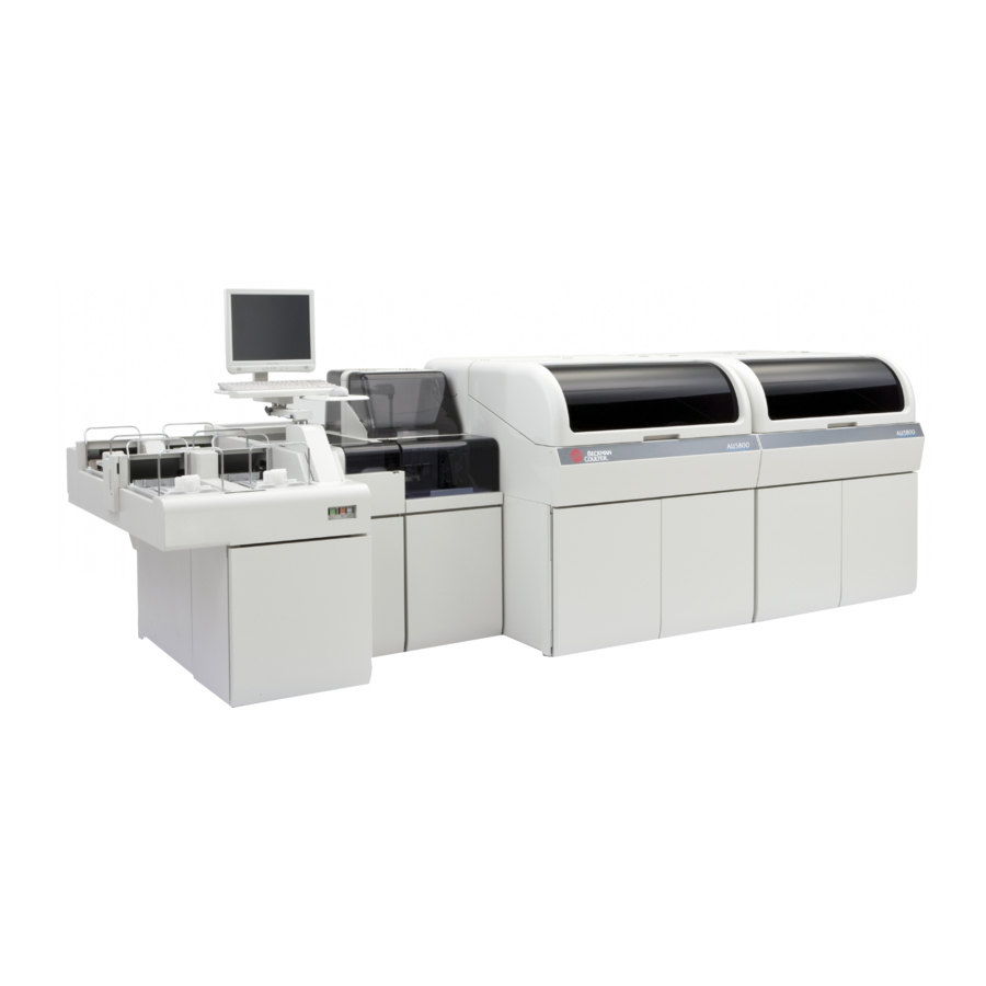
- Page 1 ® AU5800 Chemistry Analyzer Laboratory Automation Connecting Kit PN B08501AB August 2012 Beckman Coulter, Inc. 250 S. Kraemer Blvd. Brea, CA 92821 U.S.A.
- Page 2 Lismeehan O'Callaghans Mills Co. Clare Ireland Beckman Coulter do Brasil Com e Imp de Prod de Lab Ltda Estr dos Romeiros, 220 - Galpao G3 - Km 38.5 06501-001 - Sao Paulo - SP - Brasil CNPJ: 42.160.812/0001-44 製造販売業者 : ベ ッ ク マ ン・ コ ール タ ー株式会社...
-
Page 3: Revision History
Revision History This document was created as an addendum to the AU5800 User's Guide to describe the differences from the standard operation of the AU5800 when it is connected with the Beckman laboratory automation system. Refer to the AU5800 User's Guide for standard operating procedures, and all AU5800 information not specifically addressed in this addendum. - Page 4 Revision History PN B08501AB...
-
Page 5: Table Of Contents
Contents Revision History, iii CHAPTER 1: Introduction, 1-1 CHAPTER 3: System Outline, 3-1 3.4 Understanding the System Hardware, 3-2 3.4.3 LEDs and Operation Buttons (Rack Feeder Unit), 3-3 LED, 3-3 Operation Buttons, 3-5 3.4.6 Rack Feeder Unit, 3-6 Rack Feeder Unit Functions, 3-7 CHAPTER 5: Daily Start... - Page 6 Contents...
-
Page 7: Chapter 1: Introduction
CHAPTER 1 Introduction The Laboratory Automation Connecting Kit (LA kit) is an optional unit used to connect the AU5800 with the Beckman laboratory automation system automation line. This addendum to the AU5800 User's Guide describes the difference from the standard operation of the AU5800 when it is connected with the Beckman laboratory automation system. - Page 8 Introduction — No reagent probe wash solution (for a test programmed for contamination prevention). • When "Can NOT be run Test during RB/CAL" is programmed to "Enable" in System Maintenance, a test is not performed on the unit in the following conditions: —...
-
Page 9: Chapter 3: System Outline
CHAPTER 3 System Outline This chapter describes the differences in key sub-processes and hardware components of the AU5800 when it is connected with the Beckman laboratory automation system. 3.4 Understanding the System Hardware 3.4.3 LEDs and Operation Buttons (Rack Feeder Unit) 3.4.6 Rack Feeder Unit... -
Page 10: Understanding The System
System Outline 3.4 Understanding the System Hardware 3.4 Understanding the System Hardware 1. Analyzer units 10. Incubation bath unit 2. ISE unit 11. Photometry unit 3. Rack feeder unit 12. Tank unit 4. Rack buffer unit 13. Refrigerator unit 5. Rack un-loader unit 14. -
Page 11: Leds And Operation Buttons
System Outline 3.4 Understanding the System Hardware 1. Breakers and fuses 5. Sample transfer unit 2. Power supply unit 6. Syringe unit 3. Water supply/drain unit 7. Wash nozzle unit 4. Mixing unit 8. Transfer unit 3.4.3 LEDs and Operation Buttons (Rack Feeder Unit) The rack feeder unit and priority rack set unit each have LEDs to show the status of each area. - Page 12 System Outline 3.4 Understanding the System Hardware Figure 3.1 1. Rack set unit amber LED 2. RACK SET/DIAG button 3. Rack collection unit amber LED Figure 3.2 1. Rack set position 1 2. Rack set position 2 3. Priority rack set unit LED PN B08501AB...
- Page 13 System Outline 3.4 Understanding the System Hardware Operation Buttons • RACK SET/DIAG button Use this button to load a rack(s) or tray when racks are moving on the rack set unit. The green RACK SET/DIAG button LED is On and the amber LED flashes when racks are moving on the rack set unit.
-
Page 14: Rack Feeder Unit
3.4 Understanding the System Hardware 3.4.6 Rack Feeder Unit This unit is used for loading racks from the Beckman laboratory automation system to the AU5800, and unloading racks from the AU5800 to the Beckman laboratory automation system. In addition, racks can be loaded on the rack set unit or priority rack set unit and unloaded to the rack collection unit. - Page 15 Rack Flow 1. To load racks directly on the AU5800, place racks on the priority rack set unit or the rack set unit, then select . Operation of the rack loader unit supplying racks from the Beckman Start laboratory automation system is temporarily suspended.
- Page 16 System Outline 3.4 Understanding the System Hardware PN B08501AB...
-
Page 17: Chapter 5: Daily Start Up
CHAPTER 5 Daily Start Up This chapter describes the differences in the daily start up procedures when the AU5800 is connected to the Beckman laboratory automation system. 5.1 Start the System 5.1.2 Set the Start Conditions 5.8 Start Analysis PN B08501AB... -
Page 18: Start The System
9999 samples can be processed in an index. If the system is just turned on, the Index and Group can be set from the New Index window. Refer to 5.1.1 Turn On the System in the AU5800 User's Guide. Select >... - Page 19 Start Sample Numbers go to the default sample numbers, typically 0001. Unloader Change (F3) When Unconnect is selected, the racks are not transported to the Beckman laboratory automation system from the AU5800. After analysis, racks move to the rack collection unit. This setting becomes PN B08501AB...
- Page 20 Loader Change (F4) When Unconnect is selected, racks are not transported from the Beckman laboratory automation system to the AU5800. The setting becomes active at the start of analysis. Disable (F7) An option to stop analysis (disable) on a test even when the test has a requisition. Refer to 7.3 Disable a Test in the AU5800 User's Guide.
- Page 21 Daily Start Up 5.1 Start the System Set the default start sample numbers Select . The Default Start Sample No. window opens. Edit (F1) > Default Start Sample No. (F7) Figure 5.3 Enter the default start sample numbers. Select PN B08501AB...
-
Page 22: Start Analysis
Daily Start Up 5.8 Start Analysis 5.8 Start Analysis The reaction time is approximately 8 minutes and 40 seconds for the first result to be obtained after the sample is dispensed. Every 3.6 seconds, two tests can be sampled. Each analyzer unit has a maximum throughput of 2,000 tests per hour. - Page 23 Daily Start Up 5.8 Start Analysis • When the AU5800 is connected to the Beckman laboratory automation system, Measure 1 mode continues even when no more racks are supplied from the rack loader unit. To stop the analysis, select . The analyzer moves to Measure 2, then Standby.
- Page 24 Daily Start Up 5.8 Start Analysis PN B08501AB...
- Page 25 CHAPTER 6 Sample Programming and Processing This chapter describes how to prepare racks for analysis when the AU5800 is connected to the Beckman laboratory automation system. 6.2 Prepare Racks for Analysis 6.2.3 Place a Set Tray and Collection Tray on the Analyzer 6.2.4 Add Racks Directly to the System...
-
Page 26: Prepare Racks For 6.2.3 Place A Set Tray And Collection Tray On The
This section describes how to load racks on the rack set unit and priority rack set unit when the AU5800 is connected to the Beckman laboratory automation system. It is necessary to load reagent blank (blue), calibration (yellow), and QC (green) racks on the rack set unit or priority rack set unit. -
Page 27: Add Racks Directly To The
Sample Programming and Processing 6.2 Prepare Racks for Analysis Place the set tray with racks on the rack set unit, and an empty collection tray on the rack collection unit. Slide the rack stabilizing bar forward on the collection tray. CAUTION Verify the tray set indicators on the set tray and collection tray are in the correct position according to the photos below. - Page 28 Sample Programming and Processing 6.2 Prepare Racks for Analysis WARNING Never look directly into the sample ID barcode reader. The readers use lasers that can cause serious eye damage. Figure 6.3 1. Set Tray 5. Priority rack set unit LED 2.
- Page 29 CHAPTER 7 System Monitoring and Results This chapter describes the differences in the menu when the AU5800 is connected Analyzer Status to the Beckman laboratory automation system. 7.2 Monitoring Analysis 7.2.4 Analyzer Status Menu PN B08501AB...
-
Page 30: Analysis
Perform the following verifications when the AU5800 is connected to the Beckman laboratory automation system. For other verifications from not specific to connection with Analyzer Status the Beckman laboratory automation system, refer to 7.2.2 Analyzer Status Menu in the AU5800 User's Guide. PN B08501AB... - Page 31 System Monitoring and Results 7.2 Monitoring Analysis Figure 7.2 Top View of Rack Feeder Unit Figure 7.3 1. Rack Buffer Unit 4. Collection Tray 2. Rack Un-loader Unit 5. Set Tray 3. Rack Loader Unit PN B08501AB...
- Page 32 System Monitoring and Results 7.2 Monitoring Analysis Select Lab Auto, Set Tray, or Collection Tray to display the rack information. Rack Un-loader Unit: The display color indicates the status of the unit. Display Color Status Gray Normal Error Rack Buffer Unit: The line type indicates the status of the rack buffer unit. Line Type Status Normal line frame...
Need help?
Do you have a question about the AU5800 and is the answer not in the manual?
Questions and answers
the methode of Bloodsugar?