Advertisement
Quick Links
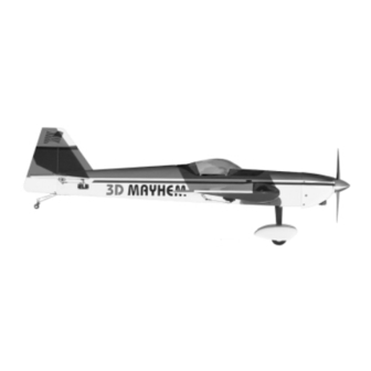
3D MAYHEM ARF ASSEMBLY MANUAL
INTRODUCTION:
Congratulations on your purchase of a SIG 3D MAYHEM ARF.
This is not your average R/C aerobatic flyer! Properly assembled,
powered and flown, the 3D MAYHEM can take you into the
exciting world of 3D aerobatic flying.
lightweight construction, and huge control surfaces with large
amounts of travel, enable the 3D MAYHEM to perform the extreme
3D maneuvers you've been reading about... hovering, harriers,
waterfalls, blenders... the 3D MAYHEM can do them all.
NOTE: The 3D MAYHEM is not suitable for beginners. While it is
a terrific flying airplane, it's neutral stability and quick controls are
beyond the capabilities of beginning R/C pilots. You should be
capable of flying low-wing, aileron equipped R/C models before
flying this airplane.
EASY TO ASSEMBLE:
The 3D MAYHEM ARF has been engineered to get you into the
air as quickly as possible with an R/C model that compares to the
best scratch-built airplanes.
constructed of the finest balsa and plywood available, then
professionally covered with tough Oracover
airplane is both rugged and easy to repair.
This assembly manual has been sequenced to get your MAYHEM
assembled and into the air very quickly. We strongly suggest that
you read through the manual first to familiarize yourself with the
various parts and assembly sequences. The successful assembly
and flying of this airplane is your responsibility. If you deviate from
these instructions, you may wind-up with problems later on.
RADIO EQUIPMENT:
We highly recommend the use of a modern programmable
computer radio. Such radio systems allow you to easily set and
adjust every channel and additionally program various flight
functions to suit your individual style of flying.
The 3D MAYHEM requires a 4 (or more) channel radio system with
five servos.
SERVO REQUIREMENTS:
Ailerons - two (2) ball bearing servos with 70+ in/oz of torque
Elevator - one (1) ball bearing servo with 70+ in/oz of torque
Rudder - one (1) ball bearing servo with 90+ in/oz of torque
Throttle - one (1) standard servo
All servos are standard size dimensionally.
R
Generous wing area,
The airframe has been expertly
®
polyester film. The
Note: The large control throws used in 3D flying require a servo
with precise centering capability. The new digital type servos have
outstanding centering characteristics and are highly recommended
for serious 3D flying. You can not expect this airplane to give you
optimum 3D performance using non-ball-bearing standard servos.
SERVO CHORDS NEEDED:
Ailerons - one standard y-harness
and
two 6" or two 12" servo extension chords
(depending upon the length of the pigtail wires on
your particular servos)
Elevator - one 24" servo extension chord
HEAVY-DUTY SERVO ARMS:
Larger than stock size servo arms are needed to achieve the large
3D control throws. We recommend Du-Bro
Servo Arms, which are available to fit any brand of servo. They are
very strong and work well with this model.
ENGINE SELECTION:
Engine choices for the 3D MAYHEM are many. The MAYHEM has
been designed to perform well when using the recommended
engine sizes. Do not use an engine larger than recommended.
RECOMMENDED ENGINES:
.72 to .91 cu.in.
.72 to 1.20 cu.in. 4-Stroke
Very Important: The 3D MAYHEM is designed for slow speed, high
torque aerobatics. It's fantastic low speed maneuverability is the
result of light weight and very large control surfaces - which are
naturally prone to flutter if flown at excessive airspeeds. To avoid
problems, follow these carefully tested guidelines:
1) Do not use engines larger than recommended. Resist the
urge to overpower your 3D MAYHEM with larger engines, which
can cause balance and structural problems, and produce
excessive airspeed.
2) Do not use a propeller with more than 6 inch pitch. Keep the
airspeed of the MAYHEM down by using low pitch propellers.
3) Do not fly full throttle except during climbs of at least 10
degrees. Always throttle back when in a dive.
Ignoring these cautions will put your model at high risk for
catastrophic in-flight structural failure.
REQUIRED TOOLS:
For proper assembly, we suggest you have the following tools and
building materials available:
A selection of glues - thin, medium, and thick SIG CA, and
SIG Epoxy Glue (5-minute and 30-minute)
1
®
"Super Strength"
2-Stroke
Advertisement

Subscribe to Our Youtube Channel
Related Manuals for SIG 3D MAYHEM ARF


Summary of Contents for SIG 3D MAYHEM ARF
- Page 1 EASY TO ASSEMBLE: excessive airspeed. The 3D MAYHEM ARF has been engineered to get you into the 2) Do not use a propeller with more than 6 inch pitch. Keep the air as quickly as possible with an R/C model that compares to the airspeed of the MAYHEM down by using low pitch propellers.
-
Page 2: Other Parts
Threadlock Compound, such as Loctite ® Non-Permanent Blue (1) Metal Rudder T-Horn Silicone Sealer - clear or white (2) 2mm x 9mm PWA Mounting Screws, for T-Horn Screwdriver Assortment 1 bag Fuel Tank Assembly: Pliers - Needle Nose & Flat Nose (1) 450cc (15.2 oz.) Plastic Tank Diagonal Wire Cutters (1) Rubber Stopper... - Page 3 COVERING MATERIAL: WING ASSEMBLY - OVERVIEW: Your 3D MAYHEM ARF has been professionally covered with The wing of the MAYHEM comes in two pieces, a right wing panel and a left wing panel, which will be permanently glued together to premium Oracover ®...
- Page 4 4) After you get the end of the servo wire all the way through 2) Use Sig slow drying epoxy glue to permanently join the two the wing, tape the loose end of the wire to the wing's top surface, wing panels together.
- Page 5 to clean up all the glue smears with a paper towel soaked in hinge. Turn the part over and apply 3-4 drops of glue to the other rubbing alcohol. Also, if possible get someone to help you with this side of each hinge. Keep a rag handy to wipe off any excess glue. proceedure.
- Page 6 2) We need to draw guidelines on the ailerons to show where to 4) Each aileron pushrod consists of a Threaded Rod with a Hex mount the control horns. Nut, a R/C Link, and a Spring Keeper on each end. a.
- Page 7 5) Now permanently glue the fuselage bottom fairing onto the bottom of the wing with thick CA glue or epoxy. Let dry. 6) a. Bolt the wing back in place on the fuselage. Locate the two Fiberglass Wing Bolt Guides and fit them into the wing bolt holes in the bottom fairing.
- Page 8 FUSELAGE ASSEMBLY, PART I: Engine Mounting: 2) Bolt the engine mounts in place on the front of the firewall For the following steps you will need these parts: using the M4 Mounting Bolts, Washers, and Blind Nuts provided. • 1 - Fuselage The blind nuts go on the back of the firewall, inside the fuselage •...
- Page 9 provided. Tighten securely. Double check to make sure that the wheels turn freely without obstruction. IMPORTANT SAFETY ISSUE! DO NOT DRILL AND TAP THE GLASS-FILLED ENGINE MOUNTS FOR BOLTS, OR USE SELF-TAPPING SCREWS OR WOOD SCREWS. THOSE METHODS WILL WEAKEN THE ENGINE MOUNTS AND CAN LEAD TO ENGINE MOUNT FAILURE! 1) Use only Socket-Head Bolts with Aircraft Lock Nuts and Flat Metal Washers to fasten your engine to the glass-filled engine...
- Page 10 the spinner backplate, through the thick APC prop, and still have enough 4) Determine the location of the hole required in the cowling for threads sticking out in front of the prop to safely use the standard Saito access to your engine's needle valve. Start with the engine and prop nut and washer.
- Page 11 Du-Bro Fueling Valve is directly on the MAYHEM firewall aileron hinges on page 5. Let dry 10 minutes before flexing the with a SIG #SIGSH759 Fueling Valve Mounting Bracket, (not hinges. Do not glue the Fin and Rudder hinges at this time! supplied).
- Page 12 wood-to-wood joint between the stab and the fuselage in the 8) The fin can now be permanently glued in place on the next step. Be very careful not to cut into the balsa wood when fuselage. Epoxy glue is recommended for this step for maximum removing the covering material.
- Page 13 that it is as far back as shown in the pictures. Use a fine felt-tip pen mounting bolt, nuts, and lock washers. Also, the control horns must to mark the locations of the 3 mounting holes onto the fuselage. Drill be positioned so they line up with an imaginary line from the control pilot holes into the bottom of the fuselage with a 1/16"...
- Page 14 4) The finished ends of the two cables prepared in the last step, RADIO INSTALLATION, PART II: Elevator: For the following steps you will need these parts: are for hooking up to the rudder control horns. Feed the unfinished • The fuselage assembly bare ends of the cables into the pull-pull exits built into the rear of •...
- Page 15 RADIO INSTALLATION, PART III: Throttle Pushrod: 5) Screw the Threaded Stud with Nylon R/C Link into one end For the following steps you will need these parts: of the 1/8” od x 15-3/4” Plastic Pushrod Tube. Use a needle nose •...
- Page 16 RADIO INSTALLATION, PART IV: Radio System: RADIO INSTALLATION, PART V: Set The Control Throws: With all the servos now installed, all that remains is the installation Use a ruler to accurately measure and adjust the travel of each of the receiver, battery pack, and switch. control surface to the amounts shown below.
-
Page 17: Fuel Tank Installation
® type cleaners all work good). You will also need a supple squeegee, (the SIG 4" Epoxy Spreader #SIGSH678 is perfect for this job), a couple clean soft cloths (old tee shirts are great), a good straight edge, a ruler, and 2) Trial fit the tank in place into the front of the fuselage to a hobby knife with sharp #11 blades. - Page 18 BALANCE THE MODEL BALANCE POINTS REFERENCE CHART This is probably the single most important step in preparing your * Percentage of Mean Aerodynamic Chord MAYHEM for flight. The final placement of the longitudinal Center % of distance aft of of Gravity, or Balance Point, is extremely important and should be approached with patience and care.
- Page 19 INCIDENCE & THRUST ANGLES: for touchdown. Gradually add more up elevator as the airplane The MAYHEM was built at the factory with the following specs: slows down and settles towards the ground. Flair the airplane as Wing Incidence: the ground approaches for a smooth 3-point landing and rollout. Hard landings are not necessary - sound piloting skills are.
- Page 20 MAYHEM LOG BOOK Date of first flight: Comments:...
-
Page 21: Academy Of Model Aeronautics
SIG MANUFACTURING COMPANY, INC. is committed to your success in both assembling and flying the 3D MAYHEM ARF kit. Should you encounter any problem building this kit, or discover any missing or damaged parts, please feel free to contact us by mail or telephone. -
Page 22: Specifications
SPECIFICATIONS: Engines: .72 to .91 2-Stroke .72 to 1.20 4-Stroke Wing Span: 72-1/8 in. (1830 mm) Wing Area: 1167 sq.in (7529 sq.cm.) Length: 59 in. (1500 mm) Flying Weight: 7 to 8 lb. (3.2 to 3.6 kg) Wing Loading: 13.8 to 15.8 oz. per sq.ft. Radio: 4-channel with 5 servos...
Need help?
Do you have a question about the 3D MAYHEM ARF and is the answer not in the manual?
Questions and answers