Table of Contents
Advertisement
Quick Links
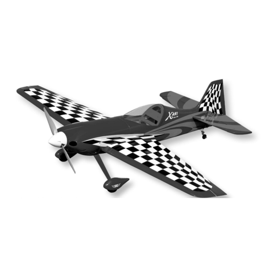
KIT NO.: SIGRC105EPARF
SPECIFICATIONS:
Wing Span:
50 in.
Wing Area:
500 sq.in.
Length:
44.25 in.
Weight
: 57 - 60 oz.
(no battery)
Weight RTF:
68 - 76 oz.
Wing Loading:
19.6 - 21.9 oz./sq.ft. (60 - 67 g/dm
Just add your own radio and electric power system:
Radio Req.:
4-Channel with 4 Micro Servos
Electric Power:
"32 Class" Brushless Motor
(700 - 900 kv, 600 - 800 watts);
60-75A Speed Control (ESC);
4S 2500 - 4000 mAh Lipo Battery Pack
SIG MFG. CO., INC.
(1270 mm)
(32.2 dm
2
)
(1124 mm)
(1616 - 1701 g)
(1928 - 2154 g)
2
)
PO Box 520
www.sigmfg.com
Montezuma, IA 50171-0520
© Copyright 2013, SIG Mfg Co., Inc.
Advertisement
Table of Contents

Related Manuals for SIG SBACH XA-41 EP ARF


Summary of Contents for SIG SBACH XA-41 EP ARF
- Page 1 “32 Class” Brushless Motor (700 - 900 kv, 600 - 800 watts); 60-75A Speed Control (ESC); 4S 2500 - 4000 mAh Lipo Battery Pack SIG MFG. CO., INC. PO Box 520 Montezuma, IA 50171-0520 www.sigmfg.com © Copyright 2013, SIG Mfg Co., Inc.
- Page 2 We hope you will enjoy this unique fun scale R/C model. Note: This numbering system is very common, Assembly of your Sbach XA-41 EP ARF is fast and simple however there are exceptions. For instance, some when following the detailed instructions in this manual. We...
-
Page 3: Covering Material
For proper assembly, we suggest you have the following tools including M2 Hex Nuts(2);for Ailerons and materials available: A selection of glues - SIG Thin, Medium, & Thick CA Glue CA Accelerator, CA Debonder SIG Kwik-Set 5-Minute Epoxy Screwdriver Assortment Pliers - Needle Nose &... -
Page 4: Wing Assembly
Caution: Trying to remove the wrinkles by hastily going over air that is sealed in those relatively small areas will expand them with a heat gun can lead to more problems. You should when the heat is applied and actually cause the covering to take your time to carefully go over the entire model with a stretch instead of shrink. -
Page 5: Hinging The Ailerons
aileron. The aileron is now in the proper position for perma- nently gluing them in place with thin CA glue. e) Holding the wing panel with the wingtip UP, drop the end of the extension chord into the servo mount cutout and then thru the openings in the wing ribs, working it towards to d) Flex the aileron down and hold it in this position. -
Page 6: Fuselage Assembly
e) Clip a Nylon Snap Keeper in place on the servo end of the pushrod wire. Snap the free end of the keeper up and over the protruding end of the pushrod wire, underneath the servo arm. f) Check that the aileron servo is in neutral position and adjust the metal clevis as needed to get the aileron in neutral position. -
Page 7: Tail Surface Installation
8) Slide a second Wheel Collar onto the axle and up to the TAIL SURFACE INSTALLATION wheel. Leave a small gap between it and the wheel, so the For the following steps you will need: wheel will turn freely, and then tighten the wheel collar set (1) Fuselage screw. -
Page 8: Radio Installation
for this job to allow time to position the stab accurately and b) Adjust the wheel collar shown to set the height of the make any final adjustments that might be needed. Apply the tailwheel wire. Then check to see if the long steering leg of the glue to both sides and reset the stab in place. - Page 9 21) Secure your receiver on the front of the plywood radio tray with one of the plastic cinch straps provided. It’s best to use a piece of foam rubber between the receiver and the ply- wood. Also, don’t tighten the cinch strap too snug - just enough to keep the receiver in place.
- Page 10 (4) M4 Split-Ring Lock Washers (4) M4 Blind Nuts (1) Hook-and-Loop Tape (Velcro ® (1) Set Electric Motor, ESC, Prop, Lipo Battery (not furnished) NOTE: The mounting of the electric motor in the Sbach XA-41 assumes that your motor has a typical "X" or "cross" mounting plate on the back of the motor.
-
Page 11: Cowling Installation
c) Run the ESC's servo cord back to the receiver and plug it in. d) Connect the ESC's motor wires to the motor. Operate the motor and check the direction of rotation. Always do this without a propeller attached! If you need to reverse the rota- tion, refer to the instructions that came with the motor and ESC. - Page 12 c) Recheck the position of the cowling and make any BALANCE POINTS FOR SPORT/PRECISION PATTERN adjustments needed to get it back in perfect position, securing The following table lists inch measurements and the equivalent the tape to hold it in place. percent of MAC (Mean Aerodynamic Chord) for typical range d) Now drill another pilot hole for the upper screw on the of balance points for sport and precision pattern flying.
-
Page 13: Control Surface Travel
visual clues of an impending stall. When put into a dive, the keep the air- plane going straight. At takeoff speed, use a neutrally-balanced plane will not self-recover; it will continue slight amount of up elevator to lift off, using ailerons to keep the on the path until the pilot gives some stick input. -
Page 14: Customer Service
WARNING! THIS IS NOT A TOY! Flying machines of any form, either model-size or full-size, are SIG MFG. CO., INC. is committed to your success in both not toys! Because of the speeds that airplanes must achieve assembling and flying the SBACH XA-41 EP ARF. Should you... - Page 15 SBACH XA-41 LOG BOOK Date of first flight:...
- Page 16 Then lift up on the back end of the hatch. Pull the hatch up and back to disen- gage the front pins and lift the hatch off of the fuselage. SIG MFG CO., INC. 401 S. Front St. Montezuma, Iowa 50171 U.S.A. Copyright 2013 SIG MFG CO., INC. Printed in Vietnam...
Need help?
Do you have a question about the SBACH XA-41 EP ARF and is the answer not in the manual?
Questions and answers