Table of Contents
Advertisement
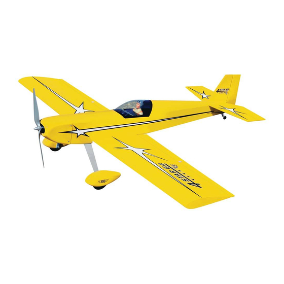
KIT NO.: SIGRC73EGARFR - (red)
SIGRC73EGARFY - (yellow)
SPECIFICATIONS:
Wing Span:
64 in.
Wing Area:
847 sq.in.
Length:
57 in.
Flying Weight:
7 - 8.25 lbs.
Wing Loading:
19 - 22 oz./sq.ft.
Radio Req.:
4-Channel with 5 Standard Servos (glow)
4-Channel with 4 Standard Servos (electric)
Glow Power:
2-Stroke .60 - .75 cu.in. (10.0 - 12.3 cc)
4-Stroke .60 - .90 cu.in. (10.0 - 14.7 cc)
Electric Power:
1200 - 1700 watt Brushless Motor (400-600 kv)
75A Speed Control (ESC)
4-6S 4000 - 5000 mAh Lipo Battery Pack
SIG MFG. CO., INC. PO Box 520 Montezuma, IA 50171-0520
(1625 mm)
(54.6 dm
)
2
(1447 mm)
(3175 - 3742 g)
(58 - 68 g/dm
2
)
www.sigmfg.com
© Copyright 2013, SIG Mfg Co., Inc.
Advertisement
Table of Contents

Related Manuals for SIG 4-STAR 64 EG ARF


Summary of Contents for SIG 4-STAR 64 EG ARF
- Page 1 Electric Power: 1200 - 1700 watt Brushless Motor (400-600 kv) 75A Speed Control (ESC) 4-6S 4000 - 5000 mAh Lipo Battery Pack SIG MFG. CO., INC. PO Box 520 Montezuma, IA 50171-0520 www.sigmfg.com © Copyright 2013, SIG Mfg Co., Inc.
- Page 2 We hope you will enjoy this unique fun scale R/C model. Here is are some motor sizes that work well in the 4-STAR 64: Assembly of your 4-STAR 64 EG ARF is fast and simple when 5030-390 following the detailed instructions in this manual. We urge you to 5062-400 read this assembly manual completely before assembly.
- Page 3 K (4) M4 Flat Metal Washers, for motor mount to firewall materials available: K (1) Fuel Tank A selection of glues - SIG Thin, Medium, & Thick CA Glue K (1) Rubber Stopper Assembly CA Accelerator, CA Debonder K (1) Fuel Pick-Up Weight (clunk)
-
Page 4: Covering Material
shirt, to prevent scratching the covering as you work. K (5) Metal RC Clevis; for ail(2), ele(1), rud(1), thr(1) After covering your iron, the next step is to set the iron to the cor- K (5) Small pieces of Fuel Tubing; for R/C clevis keepers rect temperature. -
Page 5: Wing Assembly
servo mounting screws. Use the screws supplied with your radio WING ASSEMBLY system to mount the servo in place on the servo mount. Repeat this procedure to mount the servo in the opposite wing panel. The wings are designed as a 2-piece system, with separate right and left wing panels joined by an aluminum tube wing joiner and a hardwood locating pin at the rear. -
Page 6: Very Important
e) Turn the part over and glue the other side of the hinge. Con- horn. Lay the other end of the pushrod wire over the outer hole tinue this process until you have glued both sides of all the hinges! in the servo arm. -
Page 7: Fuselage Assembly
by sliding the piece of Fuel Tubing over the arms of the clevis. wheel. Leave a small gap between it and the wheel, so the wheel Also tighten the M2 Hex Nut up against the back of the clevis. will turn freely, and then tighten the wheel collar set screw. FUSELAGE ASSEMBLY INSTALL THE MAIN LANDING GEAR Locate the following parts from the kit contents:... - Page 8 TAIL SURFACE & TAILWHEEL INSTALLATION aside for now. Test fit the fin in place on top of the stabilizer. For the following steps you will need: Check to see that the fin sits flush and perpendicular to the stabi- (1) Fuselage lizer.
- Page 9 ELEVATOR & RUDDER CONTROLS For this section you will need: (1) Fuselage Assembly (2) 35.5" long Wire Pushrods with M2 Hex Nut (2) Metal RC Clevis (2) small pieces of Fuel Tubing (2) Pushrod Snap Keepers (1) Radio Receiver (not furnished) (2) Servos with Mounting Screws (not furnished) ❑...
-
Page 10: Electric Power System
ELECTRIC POWER SYSTEM Skip this section if your using a glow engine power setup For this section you will the Fuselage and: (1) Fiberglass Cowling (4) M3 x 10mm Screws (1) Plywood Electric Motor Mount (1) Balsa Triangle Stock (4) M4 x 20mm Socket-Head Bolts (4) M4 Flat Metal Washers (4) M4 x 16mm Socket-Head Bolts (4) M4 Split-Ring Lock Washers... - Page 11 ❑ 33) Install your ESC the front. Do this along side each of the adjustment slots on both sides of the box (four marks total). a) Solder appropriate battery connectors (not supplied) to the c) After you have all four slots marked, carefully align the front battery leads of your ESC.
- Page 12 Additional Cooling Options: You may find after test flying that your ESC or battery pack need additional cooling. We have not found K 35) Mount the cowling on the fuselage with the four M3 x 10mm that to be necessary with our prototype 4-STAR 64, but it could Screws provided.
- Page 13 f) Glue the balsa block fuel tank stop in place on the plywood K 38) Start by putting the Fuel Tank together. tank tray, up against the rear end of the tank. a) Locate the Rubber Stopper Assembly. There are three nylon tubes going through the rubber stopper.
- Page 14 to the throttle servo and the engine’s throttle arm. In most cases K 45) COWLING you will want the pushrod to run right alongside the engine mount Some glow engine fliers do not use the supplied Fiberglass Cowl- and fuel tank, and then angle over to the throttle servo arm. ing, preferring to keep the front of the airplane open for easy ac- d) Drill a hole through the firewall for the nylon pushrod tube cess to the engine for fueling and service.
- Page 15 good bond. Carefully place the canopy onto the fuselage and posite effect: Moving it closer to center will decrease throw, and check it’s alignment. With a wet paper towel, wipe off any excess away from center will increase throw. Work with a combination of glue that seeps out from the canopy.
-
Page 16: Customer Service
CUSTOMER SERVICE Flying machines of any form, either model-size or full-size, are not toys! SIG MFG. CO., INC. is committed to your success in both assembling Because of the speeds that airplanes must achieve in order to fly, they 4-STAR 64 and flying the ARF.
Need help?
Do you have a question about the 4-STAR 64 EG ARF and is the answer not in the manual?
Questions and answers