Table of Contents
Advertisement
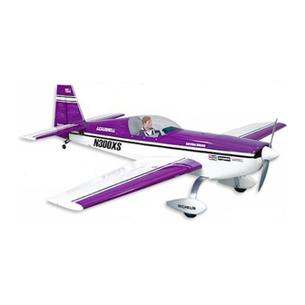
EXTRA 300XS ARF ASSEMBLY MANUAL
INTRODUCTION:
Congratulations on the purchase of your SIG EXTRA 300XS ARF
kit! Properly assembled, powered and flown, the EXTRA 300XS
will surely become one of your favorite models. The construction
of this ARF kit is extremely well engineered, providing a structure
that is very light and strong. This is one of the reasons it flies as
well as it does, using the recommended engine sizes. The EXTRA
300XS has superb take-off and landing characteristics combined
with remarkable aerobatic capabilities. The airframe has been
specifically designed to provide you with a "zeroed out" model.
This is to say that the wings and horizontal stabilizer sit at 0
relationship to the thrustline. In turn, this provides you with a model
that is completely "honest" in any attitude. We will cover more
detailed set-up information later in the assembly instructions.
3D CAPABLE!
For those of you who are interested in 3-D
aerobatics, we have provided the EXTRA 300XS with double
beveled elevator and rudder hinge lines. This means that the
control surfaces can be driven to throws in excess of 45
extreme 3-D maneuvers!
ENGINE NOTE: Due to the large number of useable engines
for this model, we simply cannot cover every possible engine
installation. However, the volume of space provided inside the
large cowling should make it easy to mount virtually any engine
within the suggested size range.
EASY TO ASSEMBLE! Since the general construction, sanding
and covering of the airplane have already been done at the
factory, the only remaining tasks are those of final assembly and
radio and engine installations.
assembly instructions closely to produce the model as it is
intended to be.
We understand that many modelers love to
"kit bash" and incorporate their own modifications. Simply be
aware that certain assembly procedures for this airplane must
be followed in the correct sequence.
instructions could lead to problems beyond our control.
carefully!
ADDITIONAL ITEMS NEEDED TO COMPLETE THIS MODEL
RADIO EQUIPMENT
We highly recommend the use of a modern programmable
computer radio. Such radio systems allow you to easily set and
adjust every channel and additionally pre-program various flight
functions to suit your individual style of flying. Four channels are
R
We urge you to follow these
Deviation from these
required to fly your EXTRA 300XS - rudder, elevator, ailerons, and
throttle. However, you will require a total of six servos - ailerons
(2), elevators (2), rudder (1), and throttle (1).
SERVOS: Since your EXTRA 300XS is a large, highly aerobatic
airplane and because the control surfaces are also large, we urge
you to use appropriate servos on all the flight surfaces (ailerons,
elevator, and rudder).
"standard" 40 - 50 inch/ounce output servos! The EXTRA is big
enough to impart very large air loads and standard servos will
quickly fail, resulting in loss of control. You should use heavy-duty
ball-bearing servos with at least 70 inch/ounces of torque or more to
drive the ailerons, elevators, and rudder. If available, use a servo
with metal gears instead of plastic gears.
prototype models we used Airtronics
elevators, and rudder. This is a dual ball-bearing servo, rated at 77
inch/ounces of torque. Another good choice is the Hitec™ #605MG
servo which has 76 inch/ounces of torque and metal gears. These
servos or their equivalent from other manufacturers, can be relied
upon to work well throughout the EXTRA's flight envelope.
"standard" servo is adequate for the throttle.
SERVO ARMS: We also suggest that you consider using after-
market reinforced plastic servo output arms, such as the Du-Bro
"Super Strength" products. These output arms are available to fit
any brand of servo. They are very strong and work well with this
model. We highly recommend their use with the pull-pull rudder
system used in this EXTRA. Using typical plastic servo output
arms with the braided steel cables for rudder control, may cause
problems due to the potential of wearing of the plastic by the
cables over extended use. The Du-Bro output arms are molded
O
in
from considerably tougher material and these have held up
extremely well in our prototypes.
SERVO EXTENSION CHORDS: You will need two 12" servo
extension chords for the ailerons, one standard Y-harness chord for
the two aileron servos and one Y-harness chord for the two
elevator servos. The Y-harness chords are used to connect two
servos to a single connector going into the receiver. In the case of
O
for
the two aileron servos a standard Y-harness chord, available from
your radio manufacturer, will work fine. In the case of the two
elevator servos see the following note about a great product called
the "Miracle Y".
Plan
MIRACLE "Y": Note in the photos that the elevator servos will be
mounted on opposite sides of the fuselage in exact "mirror image"
to each other (i.e.; with the pushrods coming off the top of each
servo in direct line with the control horns). This is done so the
geometry of the servos, pushrods, and horns is exactly symmetrical
on both sides, providing the exact same response to control inputs
for each elevator. This is very important in an all out aerobatic
machine like the EXTRA! Normally in order to have this type of
setup work properly with a standard Y-harness you would have
1
This model should not be flown with
Specifically in our
®
#94731 servos for the ailerons,
A
Advertisement
Table of Contents

Related Manuals for SIG Extra 300XS


Summary of Contents for SIG Extra 300XS
- Page 1 EXTRA 300XS - rudder, elevator, ailerons, and throttle. However, you will require a total of six servos - ailerons (2), elevators (2), rudder (1), and throttle (1). SERVOS: Since your EXTRA 300XS is a large, highly aerobatic...
- Page 2 1 Fiberglass Cowling, painted are easy to install and operate in the EXTRA 300XS. In the case of 1 Molded Plastic Tail Fairing, painted the Irvine 1.50 with a 16 x 8 APC prop, we have excellent vertical...
- Page 3 1 Left Fiberglass Wheel Pant, painted NOTE ABOUT COVERING MATERIAL 4 M3 x 15mm PWA* Bolts; for wheel pants Your EXTRA 300XS ARF has been professionally covered with Oracover ® #10 White, #54 Violet, and #71 Black. (Note: In the...
- Page 4 Remove the hatch. Redrill the holes in the hatch with a 7/64" dia. bit to allow clearance for the screws. A selection of glues - SIG Thin, Medium and Thick CA, and SIG Kwik-Set 5-Minute Epoxy Threadlock Compound, such as Loctite ®...
- Page 5 bottom surface during extremes of travel. a. Now attach 12" long servo extension chords to both aileron servos. (Note: Be sure to put a piece of tape around the connecting plugs so they can’t come apart while hidden in the wing.) b.
- Page 6 accept the square "knuckle" part of the hinge. You need to inside of the wing joiner pockets in the end of the wing panels with countersink the holes to accept the knuckle part of the hinge, so glue. Then apply a liberal coat of epoxy to the exposed center ribs that the hinge can be pushed in far enough for the pivot point to line of each wing panel.
- Page 7 wing in place into the wing saddle and check the overall fit before proceeding. 10) Locate the two 1/8" x 1-1/2" x 1-1/2" plywood wing bolt plates. The wing bolt plates are already pre-drilled in the center to pass the nylon wing bolts. Notice that there are also holes for the wing bolts pre-drilled in the rear center section of each wing panel.
- Page 8 15) Locate two 4-40 x 3-5/8" Threaded Pushrods for the 1) Horizontal and vertical engine centerline marks are scribed ailerons, two 4-40 Solder Links, two 4-40 Hex Nuts, and two 4-40 on the front of the firewall. Use a straightedge and pencil to extend Threaded R/C Links.
- Page 9 5) Use a 3/16" dia. bit to drill the four holes in the firewall for the motor mounts. After all four holes are drilled, change drill bits to a 1/4" dia. and redrill the four holes to allow clearance for the 10-32 blind nuts.
- Page 10 6-1/2" long from front to back, 6-1/2" wide at the back edge by 3-1/2" wide at the front. This size opening allows the exhaust pipes on the recommended SIG muffler for the Irvine engines to clear the cowl with plenty of additional air exit area, as well as allowing plenty of air for 4-stroke engines.
- Page 11 perfectly with the carburetor/needle valve position. Use the slip the backplate onto the engine. Slip the propeller onto the shaft Dremel Tool and tapered bit to open the hole enough to insert and and secure it with your engine's nut and washer. Snap the spinner ®...
- Page 12 blob of silicone on the front of the tank just below the neck. Slide the tank in place into the fuselage, pushing it in until the neck goes into the hole in the firewall. Do not push it all the way up tight against the firewall.
- Page 13 4) Inside the fuselage, slip the plywood throttle tube support other end, connect the solder link to your engine's throttle arm. Finally cut the cable to length inside the fuselage, leaving about over the end of the nylon pushrod tube and up against the forward 2"...
- Page 14 NOTE: Accurate alignment is ultra critical to the performance of 5) There’s one more thing to do before gluing the stabilizer an aerobatic airplane like the EXTRA. For that reason, we onto the fuselage! That is preparing the stab and elevators for recommend that you buy or borrow an accurate "incidence meter"...
- Page 15 c. Apply slow-drying epoxy glue to all the mating surfaces, and then put the fin back in place on the fuselage. Wipe off any excess glue with alcohol. Recheck the alignment, adjust as needed, and then let dry. 9) Locate the molded plastic tail fairing. Trial fit the fairing in place onto the fuselage.
- Page 16 b. Slide one of the copper swage tubes onto the end of one of e. With the rudder still taped in neutral, adjust the threaded R/C the pieces of cable. Then thread the end of the cable through the links until you get both pull-pull cables to approximately the same mild tension - it’s not necessary to pull the cables extremely tight.
- Page 17 18) As mentioned earlier, to make the elevator servos function servo output arms in place at 90 upright. Tape the elevators to the stabilizer in neutral position. Attach the solder link ends of the properly you will need to either; elevator pushrods to the servo output arms.
- Page 18 2) Slide a wheel collar onto the axle, followed by a main wheel, and then another wheel collar. Locate the outer wheel collar near the end of the axle and snug its set screw tight against the axle. Now slide the wheel and inner wheel collar out against the outer collar, and lightly tighten the inner collar set...
- Page 19 They are not intended to be a complete set of markings to duplicate one particular EXTRA 300XS. However, we think you'll agree that when applied to the SIG EXTRA as shown on the box label, they look very realistic and believable. Feel free to use all or SWITCH: The switch can be mounted onto the fuselage side or only some of the decals in different locations as you see fit.
- Page 20 ® ® ® good). You will also need a supple squeegee (the SIG 4" Epoxy Spreader #SIGSH678 is perfect for this job), a couple clean soft cloths (old tee shirts are great), a good straight edge, a ruler, and a hobby knife with sharp #11 blades. We also suggest that you have some trim tape handy for making temporary guidelines (1/8"...
- Page 21 If you have carefully followed this assembly manual, you should therefore suggest that you begin with the 27% CG location and have no real problems in test flying your EXTRA 300XS. Try to experiment from there. choose a calm day for the first flight. Good conditions will help in correctly evaluating the flight performance of the model.
- Page 22 Hard landings are not necessary, sound piloting skills are. The second flight should be even more fun because you have by We hope you will enjoy your EXTRA 300XS for a long time to now inputted any required trims learned from the first flight. Before come.
- Page 23 EXTRA 300 LOG BOOK Date of first flight: Comments:...
- Page 24 The color and markings of this ARF kit do not duplicate one particular full-scale Extra 300XS. Rather, they are a realistic selection of markings typically seen on many full-scale aerobatic airplanes.
- Page 25 SIG MANUFACTURING COMPANY, INC. is committed to your success in both assembling and flying the EXTRA 300XS ARF kit. Should you encounter any problem building this kit, or discover any missing or damaged parts, please feel free to contact us by mail or telephone.
- Page 26 TIG welded custom aluminum muffler, complete instructions, and a one-year limited warranty. Sig Manufacturing is pleased to be the exclusive distributor of First Place Engines. For the SIG EXTRA 300XS - we recommend the FPE 2.4 cu.in.
Need help?
Do you have a question about the Extra 300XS and is the answer not in the manual?
Questions and answers