Table of Contents
Advertisement
SUKHOI SU-31 ARF ASSEMBLY MANUAL
INTRODUCTION:
Congratulations on your purchase of the SIG SUKHOI SU-31 ARF
kit! We're confident that this SUKHOI will quickly become one of
your favorite models, provided it is properly assembled and
adequately powered.
This SUHKOI kit features some of the lightest, best engineered
construction of any ARF on the market. It is remarkably light and
strong! This is one of the reasons it flies as well as it does, using
the recommended engine sizes. The SUKHOI has superb take-off
and landing characteristics combined with unlimited aerobatic
capabilities.
The airframe has been specifically designed to
provide you with a "zeroed out" model. This is to say that the
wings and horizontal stabilizer sit at 0
line. In turn, this provides you with a model that is completely
"honest" in any attitude. We will cover more detailed set-up
information later in the assembly instructions.
3D CAPABLE!
For those of you who are interested in 3-D
aerobatics, we have provided the SUKHOI with double beveled
aileron, elevator and rudder hinge lines. This means that the
control surfaces can be driven to throws in excess of 45
extreme 3-D maneuvers!
ENGINE NOTE: Due to the large number of useable engines
for this model, we simply cannot cover every possible engine
installation. However, the volume of space provided inside the
large cowling should make it easy to mount virtually any engine
within the suggested size range.
EASY TO ASSEMBLE! We urge you to follow these assembly
instructions closely to produce the model as it is intended to be.
We understand that many modelers love to "kit bash" and
incorporate their own modifications. Simply be aware that certain
assembly procedures for this airplane must be followed in the
correct sequence. Deviation from these instructions could lead to
problems beyond our control. Plan carefully!
ADDITIONAL ITEMS NEEDED TO COMPLETE THIS MODEL
RADIO EQUIPMENT
We highly recommend the use of a modern programmable
computer radio. Such radio systems allow you to easily set and
adjust every channel and additionally pre-program various flight
functions to suit your individual style of flying. Four channels are
R
O
in relationship to the thrust
O
for
required to fly your SUKHOI SU-31 - rudder, elevator, ailerons, and
throttle. However, you will require a total of six servos - ailerons
(2), elevators (2), rudder (1), and throttle (1).
SERVOS: Since your SUKHOI SU31 is a large, highly aerobatic
airplane and because the control surfaces are also large, we urge
you to use appropriate servos on all the flight surfaces (ailerons,
elevator and rudder).
"standard" 40 - 50 inch/ounce output servos! The SUKHOI is big
enough to impart very large air loads and standard servos will
quickly fail, resulting in loss of control. You should use heavy-duty
ball-bearing servos with at least 70 inch/ounces of torque or more
to drive the ailerons, elevators and rudder. If available, use a servo
with metal gears instead of plastic gears.
prototype models, we used Airtronics™ #94731 servos for the
ailerons, elevators, and rudder. This is a dual ball-bearing servo,
rated at 77 inch/ounces of torque. Another good choice is the
Hitec™ #605MG servo, which has 76 inch/ounces of torque
and metal gears. These servos or their equivalent from other
manufacturers, can be relied upon to work well throughout the
SUKHOI's flight envelope. A "standard" servo is adequate for the
throttle.
SERVO ARMS: We also suggest that you consider using after-
market reinforced plastic servo output arms, such as the Du-Bro
"Super Strength" products. These output arms are available to fit
any brand of servo. They are very strong and work well with this
model. We highly recommend their use with the pull-pull rudder
system used in this SUKHOI. Using typical plastic servo output
arms with the braided steel cables for rudder control, may cause
problems due to the potential of wearing of the plastic by the
cables over extended use. The Du-Bro output arms are molded
from considerably tougher material and these have held up
extremely well in our prototypes.
SERVO EXTENSION CHORDS: You will need two 12" extension
chords and one standard Y-harness chord for the aileron servos;
one 24" extension chord for the rudder servo; and one Y-harness
chord for the elevator servos. Y-harness chords are used to
connect two servos to a single plug-in in the receiver. In the case
of the two aileron servos, a standard Y-harness chord, available
from your radio manufacturer, will work fine. In the case of the two
elevator servos, see the following note about a special kind of
Y-harness called the "Miracle Y".
MIRACLE "Y": Note in the photos that the elevator servos will be
mounted on opposite sides of the fuselage in exact "mirror image"
to each other (i.e.; with the pushrods coming off the top of each
servo in direct line with the control horns). This is done so
the geometry of the servos, pushrods, and horns is exactly
symmetrical on both sides, providing the exact same response to
control inputs for each elevator. This is very important in an all out
aerobatic machine like the SUKHOI. Normally in order to have this
1
This model should not be flown with
Specifically in our
Advertisement
Table of Contents

Related Manuals for SIG SUKHOI SU-31 ARF


Summary of Contents for SIG SUKHOI SU-31 ARF
- Page 1 SUKHOI's flight envelope. A "standard" servo is adequate for the throttle. Congratulations on your purchase of the SIG SUKHOI SU-31 ARF kit! We're confident that this SUKHOI will quickly become one of SERVO ARMS: We also suggest that you consider using after-...
- Page 2 Hinge Points, installed but not glued ENGINE & SPINNER BAG 2: LEFT WING The SIG SUKHOI SU-31 has been flown with a wide variety of Left Wing Panel engines. As everyone knows, there is no substitute for power, and Left Aileron...
- Page 3 4-40 Threaded R/C Links; ail.(2), ele.(2), rud.(1) 4-40 Hex Nuts; jam nuts R/C Links A selection of glues - SIG Thin, Medium and Thick CA, 4-40 size Solder Links; ail.(2), ele.(2), rud.(1) and SIG Kwik-Set 5-Minute Epoxy 1/16"od x 18" Stranded Steel Cable; for thr. pushrod Threadlock Compound, such as Loctite ®...
- Page 4 Masking Tape tabs that are in the wing. Remove the hatch. Redrill the holes in Paper Towels the hatch with a 7/64" dia. bit to allow clearance for the screws. Power Drill With Selection of Bits Dremel ® Tool with Selection of Sanding and Grinding Bits Soldering Iron and Solder Large Fuel Tubing WING ASSEMBLY...
- Page 5 4) Install the output arm back onto the aileron servo, in neutral Now attach 12" long servo extension chords to both aileron servos. (Note: Be sure to put a piece of tape around the position. Place the servo/mounting block assembly onto the connecting plugs so they can’t come apart while hidden in the wing.) backside of the servo hatch, centering the output arm with the half b.
- Page 6 that the hinge can be pushed in far enough for the pivot point to Next apply glue to the hardwood front wing joiner and to the line up with the front "V" point of the aileron leading edge. We aluminum tube rear wing joiner. Next slide the wing joiners into one wing panel, and then slide the other wing panel in place over recommend enlarging the opening of the hinge holes slightly with a hand-held 1/4"...
- Page 7 14) Locate the two nylon wing bolts. Mount the wing in place on the fuselage, using the nylon wing bolts. The nylon wing bolts should pass freely through the holes in the wing and thread into the blind nuts that are pre-installed in the fuselage. If the wing does not assemble cleanly and freely to the fuselage at this point, you need to find the cause of any binding and fix it now, before proceeding.
- Page 8 contact so that you have a plastic fairing-to-wood joint. Be very Holding the other end of the pushrod up next to the aileron horn, careful not to cut into the balsa wood wing sheeting while you are adjust the threaded R/C link as needed to match its connecting pin cutting away the covering material! When ready, permanently glue to the middle hole in the horn.
- Page 9 NOTE: We recommend that you use Loctite ® threadlocking compound on all bolts used in the assembly of the landing gear. 3) Locate the two main wheels, the two steel wheel axles, two axle lock nuts, and four wheel collars with set screws. Install the axles into the holes at the bottom of each leg of the aluminum main landing gear.
- Page 10 2) Horizontal and vertical engine thrust line marks are scribed Drill a 9/64" dia. hole through the firewall, aligned with your engine's carburetor throttle arm. From the front, insert the 1/8" onto the front of the firewall. Use a straightedge and pencil to nylon pushrod tube through the firewall and into the fuselage, extend the lines all the way to the edges of the firewall.
- Page 11 FPE engine to achieve the throttle setup, checking for proper movement. Make sure there is proper 6" total distance. SIG has a set of laser-cut 1/4" thick no binding. plywood spacers specifically for the FPE 2.4. They are part...
- Page 12 1) Assemble the fuel tank as shown. Be sure to label the tank and the carburetor. It allows you to pump in fuel without having to remove the carb line from the engine. We use and "vent" and "carb" lines for later identification. recommend the Du-Bro #334 GLOW Kwik-Fill Fueling Valve, and the Du-Bro #335 GAS Kwik-Fill Fueling Valve.
- Page 13 uniform and free of any loose glass. Be careful not to sand the paint on the outside of the cowl. Remove all fiberglass dust from the cowl with tac rag or with alcohol on a clean cloth. 5) We recommend a 3-1/4" dia. aluminum spinner (not supplied) for the SUKHOI.
- Page 14 5) There’s one more thing to do before gluing the stabilizer onto the fuselage! That is preparing the stab and elevators for hinging. It’s a lot easier to do it now while you can still hold the individual parts in your hands. Refer back to step 7 of the WING ASSEMBLY (on page 5) for basic guidance on installing hinges.
- Page 15 b. When satisfied with the alignment, use a felt-tip pen to mark screwing the servos in place. When done, temporarily unscrew the the fin location on top of the stab. Take the fin off and carefully elevator servos so you can install the radio "Y-harness" chord in remove the covering material from the stab just inside of the lines.
- Page 16 threads will be much stronger. Use Thin CA only, not medium or thick CA. Let the Thin CA dry completely before remounting the control horns onto the elevators. 14) Locate the two 4-40 x 2-3/4" threaded pushrods for the elevator, plus two 4-40 solder links, two 4-40 threaded R/C links and two 4-40 hex nuts.
- Page 17 b. With the rudder and tailwheel both in neutral position, apply a On our prototype models we made the bottom and back areas of small amount of tension to the spring and use the pliers to make a the canopy base light gray. The instrument panel front deck is bend at the tailwheel steering arm hole.
- Page 18 RADIO CHECK: All servo, switch, and battery connections to the good). You will also need a supple squeegee (the SIG 4" Epoxy receiver are now made. We find it easiest to leave the aileron Spreader #SIGSH678 is perfect for this job), a couple clean soft...
- Page 19 you have had time to shift it around into exact position. Once you Set the model UPSIDE DOWN on the balancing fixture and shift it have it in position, squeegee the excess soapy water out from back or forward until you find the exact spot where the model will under the decal.
- Page 20 If you need to move your balance point fore or aft slightly, the first elevator servos and securing the weights on the inside. With the method you should try is to relocate your receiver battery pack. elevator servos back in place, the weights are hidden. Often times, moving your battery pack fore or aft is all you need to do to achieve the desired balance point.
- Page 21 Holding up elevator, taxi the model to get a feel for how it handles on the ground. Make sure you have positive left and right turning ability. If not, make any adjustments needed to achieve positive ground control. Once you are satisfied with the taxi tests, line the model up with the centerline of the runway, nose into the wind.
- Page 22 SUKHOI SU-31 LOG BOOK Engine: Prop: Flying Weight: Wing Loading: Balance Point: Aileron Travel: Elevator Travel: Rudder Travel: Date of first flight:...
- Page 24 TIG welded custom aluminum muffler, complete instructions, and a one-year limited warranty. Sig Manufacturing is pleased to be the exclusive distributor of First Place Engines. For the SIG Sukhoi SU-31 we recommend the FPE 2.4 cu.in.
- Page 25 SIG MANUFACTURING COMPANY, INC. is totally committed to your success in both assembling and flying the SUKHOI SU-31 ARF kit. Should you encounter any problem building this kit, or discover any missing or damaged parts, please feel free to contact us by mail or telephone.
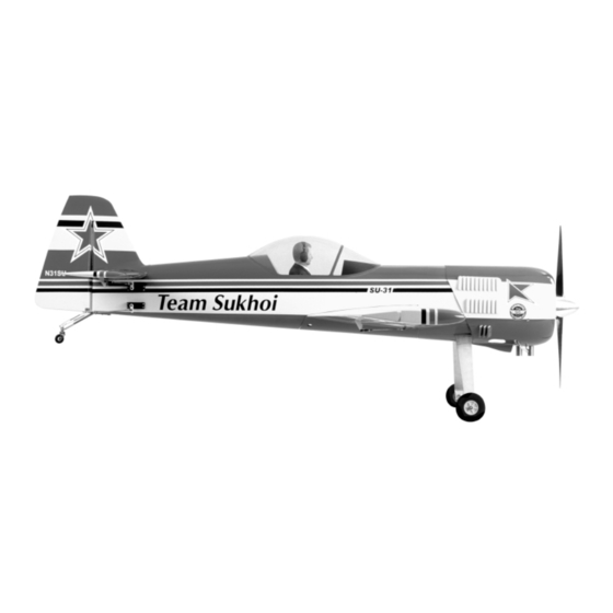
- Page 26 The color and markings of this ARF kit do not duplicate one particular full-scale Sukhoi SU-31. Rather, they are a realistic selection of markings typically seen on many full-scale aerobatic airplanes.
Need help?
Do you have a question about the SUKHOI SU-31 ARF and is the answer not in the manual?
Questions and answers