Table of Contents
Advertisement
Quick Links
Advertisement
Table of Contents

Related Manuals for SIG T-Clips EP ARF


Summary of Contents for SIG T-Clips EP ARF
- Page 1 SIG MFG. CO., INC. PO Box 520 Montezuma, IA 50171-0520 www.sigmfg.com...
- Page 2 Assembly of your T-CLIPS EP ARF is fast and simple when fol- lowing the detailed instructions in this manual. We urge you to read this assembly manual completely before assembly. Famil- K MOTOR MOUNT iarize yourself with the parts and the assembly sequences.
-
Page 3: Required Tools
For proper assembly, we suggest you have the following tools and K (1) Strip of Red Covering Material materials available: A selection of glues - SIG Thin, Medium, & Thick CA Glue CA Accelerator, CA Debonder SIG Kwik-Set 5-Minute Epoxy Screwdriver Assortment Pliers - Needle Nose &... -
Page 4: Wing Assembly
After covering your iron, the next step is to set the iron to the cor- WING ASSEMBLY rect temperature. This is critical for achieving a good result! The iron should be set to about 220 F - 250 F (104 C - 121 C) as The wings are designed as a 2-piece system, with separate right... -
Page 5: Hinging The Ailerons
system to mount the servo in place on the servo mount. Repeat Keep a rag handy to wipe off any excess Thin CA glue. (If you this procedure to mount the servo in the opposite wing panel. get some glue smears on the plastic covering, don't worry about them right now. -
Page 6: Fuselage Assembly
crosses the hole. Use a pair of pliers to put a sharp 90-degree FUSELAGE ASSEMBLY bend in the wire at the mark. INSTALL THE MAIN LANDING GEAR Locate the following parts from the kit contents: (1) Fuselage (2) Aluminum Main Landing Gear (3) M4 x 20mm Socket-Head Bolts (3) M4 Split-Ring Lock Washers (2) 2-1/2"... - Page 7 the wheels and line up the predrilled mounting holes. Secure the wheel pants in place with two M3 x 12mm socket head bolts on each pant. ❑ 13) Bolt the wing in place on the fuselage with the Nylon Wing Bolts provided.
-
Page 8: Radio Installation
to make sure the fin is absolutely 90 degrees upright to the stab. RADIO INSTALLATION For this section you will need: If needed, use a little masking tape to hold it in alignment. Wipe off any excess glue rubbing alcohol and a soft paper towel. (1) Radio Receiver (not furnished) (2) Servos with Mounting Screws (not furnished) ❑... - Page 9 c) Inside the fuselage, hold the pushrod wire over the elevator ❑ 25) Locate the pre-cut pushrod exit hole for the rudder on the servo output arm and mark the wire where it crosses over the outer hole in the servo arm. left side of the fuselage at the back of the plane and repeat step 24) in its entirety to install the rudder pushrod.
- Page 10 ❑ 28) For the T-CLIPS, we need a finished distance from the back edge of the motor mount to the motor’s thrust washer to end up exactly 4-1/2”. This is important so the cowling will fit properly. a) So what you need to do is to subtract the measurement taken in the previous step (27) from 4-1/2”.
- Page 11 c) Run the ESC's servo chord back to the receiver and plug it the top of the tab, which is putting up pressure on the tray. Once in. Use a few pieces of tape can hold the chord against the inside the tray is all the way down the slide, the tab should snap into the wall of the fuselage and out of the way of the slide-in battery tray.
- Page 12 COWLING INSTALLATION do not have access to such a power tool, you can cut the opening For this section you will need: with a drill, a hobby knife, and a sanding block - by first drilling a (1) Fuselage series of almost touching holes inside the pattern lines (1/8” dia. (1) Fiberglass Cowling works well);...
- Page 13 CONTROL SURFACE TRAVEL your airplane. Take the time to solve any power system problems The following control surface data has been flight tested with the before you try to fly. T-CLIPS. However these numbers are only recommended as a starting point. Your flying style may dictate changes. LOW RATES Elevator 3/4"...
-
Page 14: Customer Service
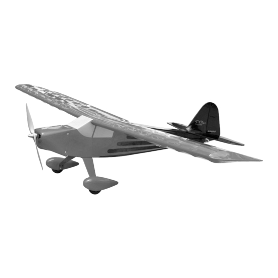
CUSTOMER SERVICE Flying machines of any form, either model-size or full-size, are not toys! SIG MFG. CO., INC. is committed to your success in both assembling Because of the speeds that airplanes must achieve in order to fly, they and flying the RASCAL 72EG ARF. Should you encounter any problem... - Page 15 "T-CLIPS" is the name given to a one-of-a-kind clipped wing Tay- C-90 (90hp) engine was installed on a late model T-craft mount, lorcraft air show airplane. The original builder is Steve Givens of with a custom cowling fabricated around a factory nose bowl. As Pendleton, Indiana.
- Page 16 “T-CLIPS” Air Show photos by: Aaron Lurth Geoff Sobering John McCullagh Lynn Towns Mike Steineke Nate Burrows Check Six Photography...
Need help?
Do you have a question about the T-Clips EP ARF and is the answer not in the manual?
Questions and answers