Table of Contents
Advertisement
Quick Links
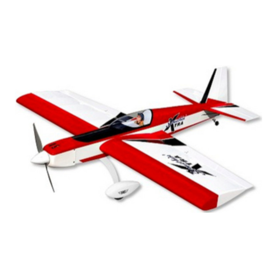
KIT NO.:
SIGRC76EGARFG -
SIGRC76EGARFR -
SPECIFICATIONS:
Wing Span:
51.5 in.
Wing Area:
725 sq. in.
Length:
48.25 in.
Flying Weight:
5 - 5.5 lbs.
Wing Loading:
16 - 17.6 oz./sq.ft.
Radio Required:
4-Channel with 5 Standard Servos (Glow)
4-Channel with 4 Standard Servos (Electric)
Glow Power:
2-Stroke .40 - .46 cu. in.
4-Stroke .53 - .65 cu. in.
Electric Power:
700 - 1000 watt Brushless Motor (550-800 kv);
75A Speed Control (ESC);
4S-6S 3000 - 4000 mAh Lipo Battery Pack
SIG MFG. CO., INC.
(Green and White)
(Red and White)
(1308 mm)
(46.7 dm
2
)
(1226 mm)
(2268 - 2495 g)
(48 - 53 g/dm
2
)
(6.5 - 7.5 cc)
(8.6 - 10.7 cc)
PO Box 520
www.sigmfg.com
Montezuma, IA 50171-0520
© Copyright 2014, SIG Mfg. Co., Inc.
Advertisement
Table of Contents

Related Manuals for SIG SIGRC76EGARFG


Summary of Contents for SIG SIGRC76EGARFG
- Page 1 Electric Power: 700 - 1000 watt Brushless Motor (550-800 kv); 75A Speed Control (ESC); 4S-6S 3000 - 4000 mAh Lipo Battery Pack SIG MFG. CO., INC. PO Box 520 Montezuma, IA 50171-0520 www.sigmfg.com © Copyright 2014, SIG Mfg. Co., Inc.
- Page 2 K POWER SYSTEM - GLOW OR ELECTRIC? The biggest decision you will have to make is whether to power your Somethin’ Xtra with a glow engine (2-stroke or 4-stroke) or an electric motor. We have flown the Somethin’ Xtra with both types of power systems, and we make the following recommen- dations based on our successful on-field experience.
-
Page 3: Required Tools
K (1) Fuel Line Tubing, for inside tank materials available: K (1) Plywood Fuel Tank Rear Mount A selection of glues - SIG Thin, Medium, & Thick CA Glue K (2) M6.5 Nylon Wing Bolts CA Accelerator, CA Debonder K (4) Nylon Control Horns; for ail(2); elev(1); rud(1) SIG Kwik-Set 5-Minute Epoxy K (12) M2 x 15mm Screws;... -
Page 4: Covering Material
iron should be set to about 220 F - 250 F (104 C - 121 C) as K (4) Nylon Pushrod Keepers; for ail(2), ele(1), rud(1) measured on the bottom of the iron using a thermometer. K (1) Pushrod Connector w/Set Screw, for throttle K (1) Small Balsa Block;... -
Page 5: Wing Assembly
system to mount the servo in place on the servo mount. Repeat WING ASSEMBLY this procedure to mount the servo in the opposite wing panel. The wings are designed as a 2-piece system, with separate right and left wing panels joined by an aluminum tube Wing Joiner and a hardwood locating Pin at the rear. -
Page 6: Fuselage Assembly
e) Turn the part over and glue the other side of the hinge. Con- horn. Lay the other end of the pushrod wire over the outer hole tinue this process until you have glued both sides of all the hinges! in the servo arm. - Page 7 Secure the axle with one of the large Hex Nuts. When tightening the hex nut, keep the flats of the nut on the axle side of the gear leg parallel to the front edge of the leg - see photo. This allows the hex nut to fit inside the narrow notch in the wheel pants when they are added later.
-
Page 8: Tail Wheel Installation
a) First view the model from directly in front. Check to see if the stabilizer is level with the wing. You should find it to be very close. If necessary use a sanding block to fine tune the stabilizer platform to level the stabilizer to the wing. b) Next use a tape measure to measure the distance from each stab tip to the back edge of the wing - the distance should be equal on both sides. - Page 9 c) Inside the fuselage, hold the pushrod wire over the elevator servo output arm and mark the wire where it crosses over the outer hole in the servo arm. ❑ 23) Figure out where and how to mount your receiver. This can depend on several factors, starting with whether you are using a glow engine or an electric motor for power.
-
Page 10: Electric Power System
❑ 25) Locate the pre-cut pushrod exit hole for the rudder on the exactly 4-1/4”, in order for the cowling will fit properly. left side of the fuselage at the back of the plane and repeat step a) So what you need to do is to subtract the measurement 24) in its entirety to install the rudder pushrod. - Page 11 blind nuts in the front firewall. If that does not work for the bottom bolts, then you will need to drill two additional holes in the bottom of the firewall that line up better with the two bottom bolts. ❑ 30) Install your ESC now, before mounting the motor perma- nently.
-
Page 12: Cowling Installation
METHOD 2 (4-5 cell pack): If your battery pack is small enough COOLING IS VERY IMPORTANT! in height you can use the supplied plywood Battery Tray. This al- K 35) With a fully cowled motor, it is very important to make sure lows you to secure your battery to the tray while it is outside the your motor is getting properly cooled. - Page 13 cess to such a tool, you can cut the opening with a drill, a hobby knife, and a sanding block. First first drill a series of almost touch- ing 1/8” holes inside the pattern lines; then use the knife to cut through the connecting material between each hole;...
- Page 14 THROTTLE PUSHROD FOR 4-STROKE ENGINES K 40) The first step is to mount your throttle servo in the fuselage, 4-stroke glow engines typically have their carburetor on the back using the rubber grommets, eyelets, and screws that came with of the engine. This puts the throttle arm very close to the firewall the servo.
-
Page 15: Complete The Radio Installation
COWLING lage. Remove the covering over the cutout you want to use, rhwn bolt the switch in the cutout. K 47) With a glow engine you might prefer to not use the cowling, so that you have quick and easy access for engine adjustments and re-fueling. -
Page 16: Customer Service
CUSTOMER SERVICE Flying machines of any form, either model-size or full-size, are not toys! SIG MFG. CO., INC. is committed to your success in both assembling Because of the speeds that airplanes must achieve in order to fly, they Somethin’ Xtra and flying the .
Need help?
Do you have a question about the SIGRC76EGARFG and is the answer not in the manual?
Questions and answers