Table of Contents
Advertisement
Quick Links
Advertisement
Table of Contents

Related Manuals for Datapath VSN400


Summary of Contents for Datapath VSN400
- Page 1 WALL CONTROLLER USER GUIDE VSN400 2nd Generation Version 1.1.0...
-
Page 2: Table Of Contents
2.2 Rack Mount Safety Instructions..............................16 2.3 Unpacking and Initial Inspection..............................16 Chapter 3 - General.........................17 3.1 Overview.........................................17 3.2 Associated Output/Input Cards and Related Products......................17 3.3 Product Datasheets....................................17 Chapter 4 - Hardware........................18 4.1 VSN400 ........................................18 Chapter 5 - Cabling.........................19 5.1 Connecting the Keyboard and Mouse............................19 Contents... - Page 3 8.2 Technical Support ....................................46 Chapter 9 - Environmental......................47 9.1 Certification and Compliances..............................47 Chapter 10 - Specifications......................48 10.1 Technical Drawings....................................48 10.2 Technical Specification - VSN400...............................49 Chapter 11 - Warranty........................50 11.1 Warranty Statement..................................50 11.2 RMA Returns Policy..................................50 Chapter 12 - Advanced Users......................52 12.1 Command Line Interface................................52...
- Page 4 Contents 12.3 Installing CODEC Packs to Play Video ............................56 12.4 Firmware Updates.....................................57 12.5 System Recovery/Restoring to Factory Settings........................57 Index..............................58 Contents...
-
Page 5: Disclaimer/Copyright Statement
© Datapath Ltd, England 2018 Datapath Limited claims copyright on this User Guide. No part of this User Guide may be reproduced, released, dis- closed, stored in any electronic format, or used in whole or in part for any purpose other than stated herein without the express permission of Datapath Limited. -
Page 6: Quick Start Guide
PCIe card product leaflets Cables/Adapters as specified in the product leaflets Each Datapath system is custom built therefore the number and type of input and output cards will differ from system to system. Accompanying this Quick Start Guide are PCIe card product leaflets which give details on how the cards are installed and any accessories supplied with them. -
Page 7: Step 3 - Connect Input Source
Step 3 - Connect Input Source Each Datapath system is custom built. The number and type of inputs will differ from system to system. Contained within the documentation pack are PCIe card product leaflets which give details on how the cards are connected. -
Page 8: Step 5 - Powering Up The System
Quick Start Guide Step 5 - Powering up the System RPSU System ATX System Connect power cables then plug into a mains supply. Switch on the power supply units. Switch on the system. Quick Start Guide... -
Page 9: Step 6 - Windows10 Setup
On the final stage of the configuration, the (DDCT) will recommend the optimum way to connect your VSN400 to your video wall displays. -
Page 10: Step 8 - Wallcontrol 10 (Optional)
Quick Start Guide Step 8 - WallControl 10 (Optional) Start | All Programs | WallControl 10 - Server Before opening the Client and Security Administration Client interfaces you will need to start the Server by clicking on it in the Programs menu. Starting the Server loads both the WallControl 10 Server and the WallControl 10 Security Server. - Page 11 Quick Start Guide Indicates the server you are connected too. A representation of the display wall(s) associated with the server. Sources Tab - Displaying all the sources connected to the server for use on the display wall. Layouts Tab - Used to save, recall and share display wall layout configurations. Templates Tab - Use templates to assist in the design of specific display wall layouts.
- Page 12 Quick Start Guide The WallControl 10 - Security Administration Client (Only Available with WallControl 10 Pro) Start | All Programs | WallControl 10 - Security Administration Client The WallControl 10 - Security Administration Client allows Administrators to assign specific users to roles on a wall by wall basis.
-
Page 13: Chapter 1 - Introduction
Chapter 1 - Introduction 1.1 Introduction Congratulations on your purchase of the Datapath Wall Controller system. The wall controller has been manufactured and tested to the highest standards offering unparalleled quality and reliability. The aim of this user guide is to assist you through the installation of the system safely and effectively and act as a reference guide for future use. -
Page 14: Terminology And Definitions
An optional software application for controlling and managing Vision, IP-Camera and third party application windows on a Datapath Wall Controller. Providing a graphical representation of the video wall and a toolbar through which to manipulate all available input sources and applications. -
Page 15: Chapter 2 - Safety
2.1 Safety Precautions To prevent damage to your Datapath product or injury to personnel operating the equipment, please read the follow- ing safety precautions prior to operation. These instructions should be made available to all those who will use and operate Datapath products. -
Page 16: Rack Mount Safety Instructions
2.2.1 Temperature If VSN400 systems are to be installed in a closed or multi-unit rack assembly, the installation should be such that the amount of air flow required for safe operation of the equipment is not compromised. The operating ambient temper- ature of the rack environment should be maintained below 35 degrees centigrade under all conditions. -
Page 17: Chapter 3 - General
Wall Monitor software (optional) - Provides monitoring of the temperature and voltage sensors on system • components 3.2 Associated Output/Input Cards and Related Products The following table lists the range of Datapath cards associated with the VSN400 range of video wall controllers: Product Description ImageDP4+ Quad output DisplayPort graphics card. -
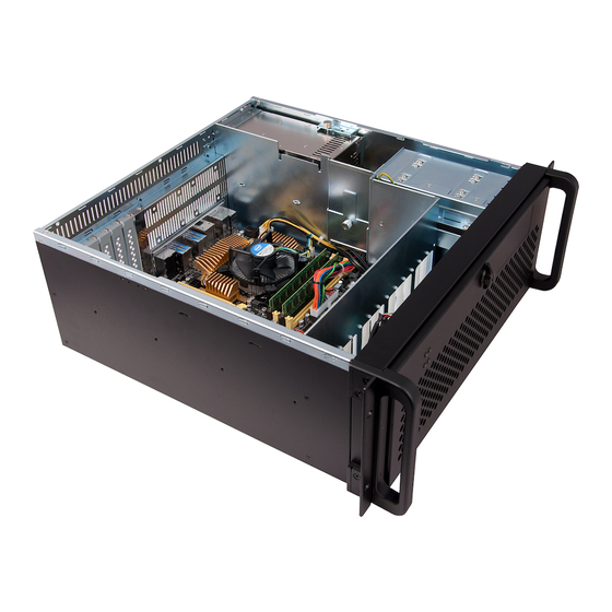
Page 18: Chapter 4 - Hardware
Chapter 4 - Hardware 4.1 VSN400 4.1.1 Front Front Panel 1 = Power, on-off 5= PSU Reset LED 2= System Reset 6= PSU Alarm 3= Power LED 7= USB Ports 4= SSD LED 8= Removable Hard Drives 4.1.2 Rear Rear Panel - RPSU... -
Page 19: Chapter 5 - Cabling
The optional WallControl 10 software enables the user to operate and manage the video wall display remotely, via a network. The VSN400 has two Ethernet ports, plug in your network cable (not supplied) to a port and connect the wall controller to the LAN, as shown below: 5.2.1 Network Security... -
Page 20: Connecting Input Sources
Contained within the product documentation folder are PCIe card product leaflets which give details on how the cards are installed and any accessories which may accompany them. For detailed information on specific cards please consult the relevant User Manual. Each capture card manual can be located on the Datapath Recovery Media supplied with your system. - Page 21 5.4.3 Connecting the Control Screen (Optional) The Datapath 2nd generation VSN 400 systems are configured to initially boot off outputs 1 and 2. The control screen is a standalone monitor which is separate from the monitors on the display wall. The control screen can be used to display the WallControl 10 application.
-
Page 22: Connecting Power Cables
In systems with an RPSU, both cables must be connected otherwise an audible alarm will be triggered when the system is switched on. Only use the power cables supplied with your system, for advice on replacements please contact Datapath. Cabling... -
Page 23: Chapter 6 - Operation
Chapter 6 - Operation This chapter will cover: Switching on • Initial system boot on delivery • Setting up the operating system • Opening WallControl 10 • Displaying video captures • 6.1 Switching On When switching the system on for the first time you will need to complete the initial system boot steps as described in Initial System Boot on Delivery below. - Page 24 Operation German • English (UK) • English (USA) • Spanish • French • Italian • Netherlands • Polish • Portuguese (Brazilian) • Russian • Simplified Chinese • 6.2.2 Select Country and Region - Windows 10 Use the dropdown menus to select the country and region, the time zone and currency and the keyboard layout. These localised settings can be changed later if required using the dialogue in Control Panel/Region and Language.
-
Page 25: Display Driver Configuration Tool (Ddct)
The DDCT Is a configuration tool designed to guide you through the design and creation of your video wall using a Datapath Wall Controller. Once the Windows Operating System has been configured and rebooted, the DDCT is displayed on your screen. - Page 26 The latest version of the DDCT is available to download from the Datapath website. To commence your wall configuration, click on “Start Wizard” (2). “Import Layout” is covered later.
- Page 27 Operation Displays With Bezels – Monitors, TV’s and DLP Cubes. • Overlapable Displays – Projectors • LED Displays. • Click on “Continue”. The tool will then display a configuration page for the type of display you selected: 6.3.2 Displays with Bezels 6.3.3 Overlapable Displays Operation...
- Page 28 Operation 6.3.4 LED Displays 6.3.5 Application Tools The application tools enable the user to manipulate the design of the wall. The table below describes the tool functionalities Undo All – Undo all commands made on this page. Undo – Undo the last command. Redo –...
- Page 29 Operation Add Button- Used to add displays to your group or to create a new group. Layout Configuration - Used to add LED modules to your group or to create a new group.. Edit - Used to edit a selected Display Group Primary Display - Indicates which display within the display group is the primary display/boot screen.
- Page 30 Operation It is strongly recommended that measurements are taken from the display manufacturers specifications if available. Cables Used Select the cable types for each monitor. Use the output configuration matrix in Chapter 5 to determine the types of output cable combinations available. An error message will be displayed if the cable limits are exceeded. 6.3.8 What Modes are the Displays Using? Use the drop down lists to select the “Mode Type”...
- Page 31 Operation It is strongly recommended that measurements are taken from the display manufacturers specifications if available. Once a layout has been designed and the type of displays have been selected you can add the displays to the representation by clicking on the “Add Displays” icon or “Layout Configurations” if LED modules are being used. When displayed on the Representation Grid”, each display can be configured separately by clicking on it.
- Page 32 You can print a copy of the wiring diagram using “Print a Wiring Diagram”. Note: The Datapath Diagnostic Suite must be installed to print a wiring diagram. To manually select the outputs right click on the display group and select “Edit”, you can then select each individual display and allocate your preferred output .
- Page 33 Operation Import Click on “Import” to import a previously saved layout. It should be noted that if the system the layout is being imported too does not have the hardware capability to run the layout, the import will be rejected. Once imported, onto the system, the layout can be edited in the “Manage Display Group”...
- Page 34 Operation The “Manage Display Groups” dialogue allows you to edit current groups and create new groups. In the example above two groups have been created. Hover the mouse over each group (10) to display basic information about the display group: The group name •...
-
Page 35: Opening Wallcontrol 10 (Optional)
Operation 6.4 Opening WallControl 10 (Optional) WallControl 10 is an optional video/display wall management software application specifically designed for Datapath Wall Controllers. WallControl 10 consists of two separate elements that work together to enable you to control the display wall, the Client (application) and the Server. - Page 36 Operation 6.4.6 WallControl 10 Security Administration Client The WallControl 10 Security Administration Client allows Administrators to assign specific user roles on a wall by wall basis. Users are assigned Roles based on their Windows login. Roles can be structured to allow only specific tasks to be carried out on a wall using the WallControl 10 Client.
-
Page 37: Chapter 7 - Software
Chapter 7 - Software This chapter will cover: WallControl 10 • Wall Monitor • Utilities • 7.1 WallControl 10 (Optional) WallControl 10 provides users with interface required to quickly and effectively manage content that includes video captures, IP streams and local applications. Users are able to place any input source on any part of the video wall using a simple drag and drop operation. - Page 38 Software The WallControl 10 - User Interface Indicates the server you are connected too. A representation of the display wall(s) associated with the server. Sources Tab - Displaying all the sources connected to the server for use on the display wall. Layouts Tab - Used to save, recall and share display wall layout configurations.
- Page 39 Software When opened, the display wall tab shows a live representation of the physical wall and the sources available to display on it. To place a source on the video wall, simply click on the required source in the sources tab and drag it onto the display wall representation.
-
Page 40: Wall Monitor (Optional)
Software 7.2 Wall Monitor (Optional) The optional Wall Monitor software application enables you to monitor the temperatures and voltages of the following system components: Backplanes • Capture Cards • SQX Cards • Motherboard • CPU Cores • Graphics Cards • Should any overheating or voltage surge be imminent within the system, the Wall Monitor application will alert the user via a pre-configured alarm. - Page 41 Software 7.2.2 Wall Monitor Application Window The Wall Monitor application window (above) is displaying the temperature of the capture cards in the system. To view different components, click on the relevant tabs. Temperatures can be displayed in either degrees Fahrenheit or degrees Celsius.
-
Page 42: Vision Application (Optional)
User Mode filter for source selection: Enables cropping support in DirectShow on all inputs • Supports Start and Stop trigger interface on all Visi0n inputs • Datapath Unified Vision Driver: Multiple cards per system, 16 streams per input • Frame sync and time stamping •... - Page 43 • 7.3.3 MultiStream Datapath’s MultiStream feature is available on all Datapath capture cards and enables multiple, independently format- ted video streams to be set up in parallel. Each stream can be formatted completely independently and individual selection of resolution, colour space and crop- ping region can be set for each stream.
-
Page 44: Software Utilities
7.4 Software Utilities Datapath provides a group of software utilities designed to assist you fine tune your system for specific individual sys- tem requirements. All the software utilities can be found on the Recovery Media that was shipped with your system, alternatively, you can download the most up-to-date versions from the Datapath website. -
Page 45: Chapter 8 - Maintenance
Ideally, the filter should be cleaned using a vacuum cleaner. Note: The filter should never be immersed in water or any other cleaning liquid. For advice on replacement filters, please contact Datapath Ltd. Troubleshooting... -
Page 46: Technical Support
During the support process you may be asked by one of our support staff to carry out certain tasks and procedures to assist them in solving any problem you may encounter. Details and up to date instructions can be found in the support section of the Datapath website. Maintenance... -
Page 47: Chapter 9 - Environmental
9.1.3 Disposal At the end of life all Datapath products should be disposed of as per local laws and regulations dictate. In the UK con- tact Datapath to arrange disposal. Our WEE registration number is WEEE/AA0005ZR. Environmental... -
Page 48: Chapter 10 - Specifications
Chapter 10 - Specifications This chapter will cover: Technical drawings of the chassis • Technical specifications • 10.1 Technical Drawings Specifications... -
Page 49: Technical Specification - Vsn400
Specifications 10.2 Technical Specification - VSN400 Motherboard COTS ATX motherboard with HDMI & DisplayPort control screen Expansion Slots 4 x PCIe x8 Gen3 USB Connectivity 2 x USB 3.1 Ports (1 x type A, 1 x type C) 4 x USB 3.0 Ports 4 x USB 2.0 Ports... -
Page 50: Chapter 11 - Warranty
11.1 Warranty Statement Datapath provides a return to manufacturer warranty on all its products for a standard 36 month period, see the table below for non standard warranty periods. It is important that RMA procedures are followed prior to products being returned as often issues can be resolved quickly without the need for products being returned. - Page 51 Once the RMA Number has been issued, you need to raise your Purchase Order, or supply your credit card details, and return the product to: Datapath Ltd, Bemrose House, Bemrose Park, Derby DE21 6XQ, United Kingdom - securely packed and with the RMA Number clearly displayed on the outside of the box. To prevent unnecessary carriage and handling please only send back products or accessory items you believe to be faulty.
-
Page 52: Chapter 12 - Advanced Users
Chapter 12 - Advanced Users This chapter is aimed towards advanced users and covers the following: WallControl 10 Command Line Interface • Software Development Kit (SDK) • RAID • ImageDP4+ Video BIOS • Replacing Cards • Updating Firmware • System Recovery •... - Page 53 Advanced Users Command line arguments are provided with both a long switch and a short switch where shown. Nomenclature Italic – Information you must supply. Bold – Elements that must be typed exactly as shown. Between brackets [ ] – Optional items Between braces { } Set of choices (separated by | ) from which you must choose only one.
- Page 54 Advanced Users -id=number When a window is created it can be allocated in ID. To modify or close a window, specify its ID so the correct window is addressed. Only one window can exist on the wall at any time with the allocated ID. -window -window=[top],[left],[width],[height] Set the position and size of the window.
- Page 55 Advanced Users Example Commands Below is a list of example commands: 1. Open a Vision window using Vision input number 2 positioned at the top left of the wall with a height and width of 500 pixels: wcmd –machine=10.0.0.21:8099–id=1 –provider=Capture–input=2–window=100,100,500,500 2.
-
Page 56: Verify Raid
Advanced Users 12.2 Verify RAID To verify the RAID set up on your Wall Controller follow these instructions. 13.2.1 Enter the BIOS Setup Restart the Wall Controller and press the keyboard delete button when the Boot-Up splash screen is displayed. This will direct you to the BIOS Setup Utility. -
Page 57: Firmware Updates
Datapath do not provide any warranty or assurance that these examples will be suitable for commercial use. We simply list them as an example of those available through 3rd parties. Before deployment we advise that any of the above, and any other codec selected, is thoroughly evaluated to confirm their suitability. -
Page 58: Index
Control Screen 21 Maintenance 15 Create and edit roles 12, 39 Manufacturer Warranty 50 Mechanical Loading 16 Move displays 28 Datapath Display Configuration Tool 25 Multi-unit rack assembly 16 DDCT 25 Degraded RAID Array 56 Desktop Utility 44 Network Security 19... - Page 59 Index WallControl 10 - Server 35 WallControl 10 Server 10, 37 Safety 15 Wall Control-SQX 44 Screen Order 20 Wall Monitor Application 41 Security Administration Client 12, 39 Wall Monitor Software 40 SecurityOnOff.exe 12, 39 Wall Naming 29 Security Server 10, 37 What display module are you using? 30 Selecting a Boot Device 57 Windows 10 Setup 9...
Need help?
Do you have a question about the VSN400 and is the answer not in the manual?
Questions and answers