Table of Contents
Advertisement
Quick Links
Advertisement
Table of Contents

Subscribe to Our Youtube Channel
Related Manuals for Circutor C-80


Summary of Contents for Circutor C-80
- Page 1 SYSTEM ANALYZER C-80 INSTRUCTION MANUAL (M98117501-03 / 04B) CIRCUTOR S.A.
-
Page 2: Table Of Contents
3.1.- Values measured in balanced three phase mode and single phase mode....6 3.2.- Connection diagrams ....................7 3.2.1.- Connecting a current clamp ................9 3.3.- Functions of the keypad ....................9 3.4.- Starting measuring with the C-80...................10 3.5.- Presentation of data on the display................11 4.- PROGRAMMING AND PARAMETER DISPLAY ............13 4.1.- Basic setting diagram.....................13 4.2.- Measurement menu .......................14... -
Page 3: Introduction
(or simultaneously) records data in the internal memory at regular time intervals. This manual assists in the installation and use of C-80 type measuring instruments and helps to obtain the best service from it. Carefully read this manual before connecting the equipment to avoid incorrect use which may cause irrevocable damage. -
Page 4: General Features
The instant maximum, minimum values, recorded values and THD alarms can be displayed. Power supply: The C-80 Analyzer is powered by two standard 1.5 V AA type batteries. The independent operating period is about 200 hours. The equipment switches itself off after 5 minutes if not recording. -
Page 5: Connection And Start-Up
500 V AC. between voltage inputs. Maximum measurable current: according to clamps used. Whenever a clamp is connected, the C-80 auto-detects the clamp and stores the configuration (Current primary) of the clamp automatically in the setup. This does not occur with the CP-5 clamp. This is due an external transformer that has to manually programmed. -
Page 6: Values Measured In Balanced Three Phase Mode And Single Phase Mode
3.1.- Values measured in balanced three phase mode and single phase mode In three phase mode, the three phases must be connected in the correct fashion plus a current clamp to measure current. The C-80 measures power consumed. Balanced three phase value Single phase value... -
Page 7: Connection Diagrams
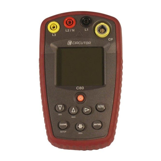
NOTE: The L1 and L2 voltage terminal connections take the measurement. The L3 terminal → → is for checking the turn direction of the phases (1 If the phases are incorrectly connected the C-80 will display the prescribed turning direction. (See section 3.5 Presentation of data on the display). - Page 8 2. V2-N / I2 3. V3-N / I3 The C-80 will measure values per phase. If the total power (W or var) is required the measured powers the measured powers have the measured powers have to be added P1 + P2 + P3.
-
Page 9: Connecting A Current Clamp
C-80 is a two quadrants instrument. The user does not need to concern himself with the direction of the current clamp. If the direction of the current is unknown, the C-80 internally changes the direction so that it always measures power consumed 90º... -
Page 10: Starting Measuring With The C-80
If this is not done, it may mean that the measurements are not correct. The C-80 Analyzer has an energy saving system. If no key is touched for 5 minutes, the C-80 switches itself off. This does not occur if the equipment is recording. -
Page 11: Presentation Of Data On The Display
-------------- SYSTEM ANALYZER C-80 ----------- Page no. 3.5.- Presentation of data on the display On the liquid glass display (LCD) 7 segments of 3 lines and 4 digits per line with indicating icons, the instant, maximum, minimum values can be displayed, along with recorded values and configuration screens. - Page 12 -------------- SYSTEM ANALYZER C-80 ----------- Page no. Setup menu: ICON MODE Description Units Indicates the variable unit that can be edited Set up screen for maximum demand variable and period %THD (V/I) ON Set up screen for harmonic distortion alarm...
-
Page 13: Programming And Parameter Display
4.- PROGRAMMING AND PARAMETER DISPLAY 4.1.- Basic setting diagram To set the C-80 and to display the parameters required by the user in an easy and intuitive way, the C-80 is divided into a series of display and setting menus selected via the keypad. -
Page 14: Measurement Menu
Page no. 4.2.- Measurement menu This menu allows the measured parameters to be displayed in real time by the C-80. This menu only displays the parameters and nothing may be set nor edited. Using the [▼] and [▲] keys, we can move between the different screens displaying the instant values. - Page 15 -------------- SYSTEM ANALYZER C-80 ----------- Page no. Measurement menu diagram: MEASUREM. MENU RL1 RL2 MAX MIN REG V, I, Hz /( * kvarh MAX MIN REG Capacitive Reactive Energy kvar RL1 RL2 MAX MIN REG +( 1 - Powers kvar...
-
Page 16: Setup Menu
-------------- SYSTEM ANALYZER C-80 ----------- Page no. 4.3.- SETUP menu To access the SETUP menu press for a long time the [SETUP] key, from the Measurement menu. The screen will show [Set In]. To exit the SETUP menu press for a long time the [SETUP] key. The screen will show [Set Out]. - Page 17 -------------- SYSTEM ANALYZER C-80 ----------- Page no. SETUP MENU Screen 1 RL1 RL2 Allows the editing of date: Day. Month Clock editor ENTER Year kvarh Time Screen 2 RL1 RL2 Configuration of the Current transformation ratio of the editor ENTER primary current primary.
-
Page 18: Capacitor Mode
MAX MIN REG Flashing kvarh +* ( b. Introduce power in Cosϕ kVAR: On introducing the required value of Cosϕ the C-80 calculates the power in kVAR in order to do the correction. RL1 RL2 MAX MIN REG kvarh +* ( Flashing When the equipment is in capacitor use it stops recording if so doing). -
Page 19: Clear Mode
-------------- SYSTEM ANALYZER C-80 ----------- Page no. 4.5.- CLEAR mode To access CLEAR mode, press once the [CLEAR] key from the Measurement menu. To exit, press the [CLEAR] key again and return to the measurement menu. On exiting the action is entered and it returns to the measurement menu. -
Page 20: Registering Menu
The C-80 ANALYZER has the option to record the measurements and store them in a non- volatile rotating memory with a capacity of up to 33 recordings. The C-80 has an option to register up to 33 measurements and store them in the non-volatile rotating memory. It has a rotating file, meaning that once the 33 recordings are full it will continue registering new data in the oldest position. -
Page 21: Timed Registers
15 minutes. 4.6.2.- Instant registering THE C-80 ANALYZER allows instant registers of the measurements, i.e. taking a "photo" of the present measurements The values registered will be those measured instantaneously The variables will be the same as the timed registers except that the maximums and minimums will be those on the display and not those from a preset period. - Page 22 -------------- SYSTEM ANALYZER C-80 ----------- Page no. Recording of variables: The 21 measurement variables recorded are: Variable Description Average instantaneous voltage Average instantaneous current Average instantaneous active power kvar Average instantaneous reactive power Average instantaneous frequency Power factor of the averaged measurements COS ϕ...
-
Page 23: Additional Current Leakage Screen
4.7.- Additional current leakage screen To the portable C-80 there can be connected a clamp to detect leakages in the system. The operation of the C-80 on connecting a CF (leakage clamp) is different to that when connecting other types of clamp. -
Page 24: Technical Features
-------------- SYSTEM ANALYZER C-80 ----------- Page no. 5.- TECHNICAL FEATURES Measured line voltage margin 70-500 V AC. Voltage overrange 10% (550 V AC.) Accuracy voltage measurement 0.5% ± 2 digits Measured current margin 2 Vrms (depending on clamp) Current overrange Accuracy current measurements 0.5% ±... -
Page 25: Frequently Asked Questions
-------------- SYSTEM ANALYZER C-80 ----------- Page no. 6.- FREQUENTLY ASKED QUESTIONS The equipment does not measure correctly Ensure that the equipment is in correct mode (single phase / three phase) according to the type of installation and that the equipment is correctly connected. -
Page 26: Maintenance
Page no. 7.- MAINTENANCE The C-80 does not require any special maintenance. Any adjustment, maintenance or repair to the open equipment is to be avoided. If it cannot be avoided it must be undertaken by someone qualified and well informed of the necessary action.
Need help?
Do you have a question about the C-80 and is the answer not in the manual?
Questions and answers