
Related Manuals for Rosslare MD-W11N


Summary of Contents for Rosslare MD-W11N
- Page 1 MD-W11 Wireless Access Control Door Interface Installation Manual MD-W11N MD-W11F MD-W11BP...
- Page 2 ROSSLARE. ROSSLARE reserves the right to revise and change this document at any time, without being obliged to announce such revisions or changes beforehand or after the fact.
-
Page 3: Table Of Contents
Available Models ..............12 Installation and Wiring ..........13 The Installation Kit ..............13 General Installation Requirements .......... 14 Installing the MD-W11N Unit ..........14 Wiring the MD-W11N Unit ............ 15 Installing the MD-W11F Unit ..........18 Wiring the MD-W11F Unit ............. 19 Installing the MD-W11BP Battery Pack........ - Page 4 Table of Contents Limited Warranty ............28 MD-W11 Installation Manual...
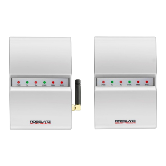
- Page 5 List of Figures List of Figures Figure 1: MD-W11 Interface ................8 Figure 2: MD-W11 Back Cover ................ 14 Figure 3: Near Unit Wiring Diagram ..............15 Figure 4: Sample Wiring Detail ................ 17 Figure 5: Far Unit Wiring Diagram ..............19 Figure 6: LED Display Panel ................
- Page 6 List of Tables List of Tables Table 1: DIP Switch Settings ................22 Table 2: Unit Channels Setting ................ 23 MD-W11 Installation Manual...
- Page 7 ROSSLARE exclusive warranty and liability is limited to the warranty and liability statement provided in an appendix at the end of this document. ...
-
Page 8: Introduction
Near Unit Far Unit Battery Pack The Near Unit is connected to a Rosslare door controller (such as AC- 215, AC-225, or AC-525). The Far Unit is connected to proximity card readers or keypads (such as AY-K12 and AY-Q64B). When a card is read or a code is entered by keypad, the Far Unit transmits the information to the Near Unit. -
Page 9: Features
The MD-W11 Wireless Access Control Door Interface includes: Bi-directional RF data communication Supports PIN codes and card formats, such as Wiegand 26-Bit, Wiegand 32-Bit, and Wiegand 6-Bit Rosslare formats (see Section 2.1). Lock and door relay commands ... -
Page 10: Technical Specifications
(with external Range depends on RF related environmental conditions. antenna) Response Time Up to 500 ms with Rosslare’s AC-215 controller and reader Response time depends on RF link quality, number of doors used, and controller and reader response time. Output Relays... -
Page 11: Supported Card Transmission Formats
Wiegand 34-Bit Wiegand 40-Bit Supported Keypad Transmission Formats Single Key, Wiegand 6-Bit (Rosslare format, default) Single Key, Wiegand 6-Bit with Nibble and Parity bits Single Key, Wiegand 8-Bit, Nibble Complemented 4 Keys Binary, Wiegand 26-Bit ... -
Page 12: Available Models
Technical Specifications Available Models MD-W11NHR (869 MHz) MD-W11FHR (869 MHz) MD-W11NGR (433 MHz) MD-W11FGR (433 MHz) MD-W11BP MD-W11 Installation Manual... -
Page 13: Installation And Wiring
The battery pack is mounted only on the MD-W11 Far Unit side (see Section 3.7). The MD-W11N and the MD-W11F are connected to the controller and the door components (lock, door monitor, reader). Both units are transceivers; the Near Unit receives the data transmitted from the reader and sends it to the controller. -
Page 14: General Installation Requirements
Fixed external antenna (G Model) Installing the MD-W11N Unit The Near Unit can be connected to a standard Rosslare controller, such as the AC-225. To install the Near Unit: 1. Use the spline key to remove the case security screw from the back of the unit (Figure 2). -
Page 15: Wiring The Md-W11N Unit
4. Wire the unit as instructed in Section 3.4. Wiring the MD-W11N Unit Wire the following terminals between the controller's input and output to the MD-W11N Near Unit, as shown in Figure 3: Figure 3: Near Unit Wiring Diagram MD-W11 Installation Manual... - Page 16 Installation and Wiring Power supply connections (+12V and GND) STAM – System tamper SPV – Supervision failure (Far Unit has supervision failure) LBAT – Low battery (Far Unit has low battery) AC Fail – Far Unit has power failure D0 –...
-
Page 17: Figure 4: Sample Wiring Detail
Installation and Wiring Figure 4: Sample Wiring Detail Figure 4 shows sample input connections to any inputs, and is relevant to AC-215/225/525. The relevant input can be configured to result in the required outcome, using AxTrax and Panel Links. • The connection between the REX Input and Relay 1 is always COM+ N.O. -
Page 18: Installing The Md-W11F Unit
Installation and Wiring Installing the MD-W11F Unit The Far Unit can be connected to a standard Rosslare reader, such as the AY-K12. The optional battery box can then be attached to the wall next to the Far Unit. To install the Far Unit: 1. -
Page 19: Wiring The Md-W11F Unit
Installation and Wiring Wiring the MD-W11F Unit Wire the following terminals between the controller's input and output to the Far Unit, as shown in Figure 5: Figure 5: Far Unit Wiring Diagram 12–24 VAC or 15–24 VDC to the VIN+ and VIN- ... -
Page 20: Installing The Md-W11Bp Battery Pack
3. Use the hardware provided to mount the back plate on the wall. 4. Wire the battery pack as described in Section 3.8. The battery pack comes with a battery installed. The size of the case is compatible with Rosslare’s BT-05 12 VDC/800 mA SLA rechargeable battery. Wiring the MD-W11BP Battery Pack... -
Page 21: Installer Recommendations
Installation and Wiring Rx – Receiving transmission ENRL – Enrolling TRBL – Trouble SYS – System OK 3.10 Installer Recommendations To install the MD-W11 units most efficiently, place the Near and Far Units facing each other, rather than placing them at a 90º angle to one another. -
Page 22: Enrollment
Enrollment 4. Enrollment Prevent loss of transmission data by enrolling each pair of Near and Far Units. Enrolling the Units One unit cannot recognize the unique ID of another unit unless both units are enrolled so that they can work together. DIP Switches The DIP switches on both units are set as shown in Table 1. -
Page 23: Near And Far Unit Modes
Enrollment Set the unit channels with DIP Switches 5 and 6 as shown in Table 2. Table 2: Unit Channels Setting DIP Switch 5 DIP Switch 6 Channel Channel H Model G Model 869.50 MHz 433.60 MHz 868.45 MHz 433.40 MHz 868.30 MHz 433.20 MHz 868.15 MHz... - Page 24 Enrollment A blinking TRBL LED indicates that there is trouble. Refer to Section 4.2.1.3 for a list of possible problems. 4.2.1.2 Enrolling Mode Enrolling mode is used for retention of transmitted data. To set the Enrolling mode: 1. Set DIP Switch 7 on both units (Near and Far) to Off. 2.
- Page 25 Enrollment Following detection of any of the said problems or failures, the Far module behaves as shown in the following table: Problem Activity Reader Tamper Sends trouble and problem to the Near module Far Module Tamper Sends trouble and problem to the Near module Low Battery Sends trouble and problem to the Near module (Trouble LED turns on)
-
Page 26: Operational Information
Operational Information 5. Operational Information The units should be no more than 300 meters from one another in an open field. The Far Unit has one DIP switch with eight buttons, the default for all of which is On. The end user only uses Button #7 to enroll the Near and Far Units. -
Page 27: Declaration Of Conformity
Declaration of Conformity Declaration of Conformity This device complies with Part 15 of the FCC Rules. Operation is subject to the following two conditions: This device may not cause harmful interference. This device must accept any interference received, including interference that may cause undesired operation. - Page 28 Limited Warranty Limited Warranty The full ROSSLARE Limited Warranty Statement is available on the ROSSLARE website at www.rosslaresecurity.com. Rosslare considers any use of this product as agreement to the Warranty Terms even if you do not review them. MD-W11 Installation Manual...
- Page 29 Tel: +86-755-8610 6842 Fax: +86-755-8610 6101 Rosslare Security Products, Inc. support.cn@rosslaresecurity.com Southlake, TX, USA India Toll Free: +1-866-632-1101 Local: +1-817-305-0006 Rosslare Electronics India Pvt Ltd. Fax: +1-817-305-0069 Tel/Fax: +91-20-40147830 support.na@rosslaresecurity.com Mobile: +91-9975768824 Europe sales.in@rosslaresecurity.com Rosslare Israel Ltd. Rosh HaAyin, Israel...
Need help?
Do you have a question about the MD-W11N and is the answer not in the manual?
Questions and answers