Lenze i510 protec Series Operating Instructions Manual
Ip20/nema 1
Hide thumbs
Also See for i510 protec Series:
- Commissioning (487 pages) ,
- Service manual (250 pages) ,
- Operation manual (127 pages)

Related Manuals for Lenze i510 protec Series


Summary of Contents for Lenze i510 protec Series
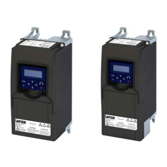
- Page 1 Operating Instructions | US Inverter i510 protec IP20/NEMA 1 0.5 ... 7.5 hp (0.37 ... 5.5 kW) As easy as that.
- Page 2 Overview Overview Hardware overview of the inverter Control terminals Network status LEDs Standard I/O Memory module Diagnos�c module Keypad, WLAN module or USB module Netw rk, Op�on X2xx CANopen or Modbus RTU Inverter status LEDs Relay output Mains connec�on X100 Shield connec�on Control cable Motor connec�on...
-
Page 3: Table Of Contents
Contents Contents 1 General information ................... 4 Commissioning....................17 1.1 Target group ......................4 7.1 Initial switch-on ....................17 1.2 Application as directed ..................4 7.2 Keypad module ....................17 1.3 Device-specific standards and directives .............. 4 7.2.1 Functions of the keys ................18 1.4 Relevant standards and directives for the operator .......... -
Page 4: General Information
• UL 61800-5-1 and CAN/CSA C22.2 No.274 are the North American product documentation. electrical safety standards. The complete documentation, further information and tools regarding Lenze products can be found on the Internet: https://www.Lenze.com Relevant standards and directives for the operator Application as directed Target group • If the product is used in accordance with the technical data, the drive Work on the product must only be carried out by qualified personnel. -
Page 5: Identification Of The Products
For the design type with a keypad, the first 0 is replaced by the letter K; applications. Lenze does not take any responsibility for the suitability of for the WLAN type, it is replaced by the letter W. -
Page 6: Layout Of Warning Notices
Safety instructions Layout of warning notices Residual hazards Safety instructions protect against injury to persons or damage to The user must take the residual hazards mentioned into consideration in property. The measures described for the prevention of hazards must be the risk assessment for his/her machine/system. complied with. -
Page 7: Technical Data
Technical data Technical data Standards and operating conditions Conformities 2014/35/EU, 2014/30/EU, 2011/65/EU TR CU 004/2011, TR CU 020/2011 Approvals UL 61800-5-1, CSA 22.2 No. 274 Energy efficiency Class IE2 EN 50598-2 Degree of protection IP20 EN 60529 For completely and correctly NEMA 250 Type 1 installed device. UL 50 Power systems TT, TN... -
Page 8: Mechanical Installation
Mechanical installation Mechanical installation Dimensions and assembly Rated power Weight Inverter [screws + hole spacing] 1-phase mains connection 120-V devices 0.5 ... 1.5 I51APxxxA 7.87 3.94 4.09 8.66 2.83 >1.97 >1.97 0.37 ... 1.1 1-phase mains connection 230/240-V devices 0.5 ... 3 I51APxxxD 7.87 3.94... -
Page 9: Cable Entries With Shield Support
Open and close the cover Open and close the cover Cable entries with shield support The cable glands are located on the underside of the device. ► For wiring purposes, loosen the cover using a screwdriver. 1. Insert the screwdriver into the slot device bottom and press. 0.5 ... -
Page 10: Electrical Installation
Electrical installation Electrical installation EMC-compliant installation The drive system of inverter and drive meet the EMC Directive General overview of the connections 2014/30/EU if they are installed according to the guidelines of CE-typical The connection diagram is considered exemplary for all voltage and drive systems. These guidelines should also be followed in installations power classes. -
Page 11: Control Terminals
Electrical installation Control terminals Relay output Control terminals The relay is not suitable for direct switching of an electromechanical holding brake. Use a corresponding suppressor circuit in case of an inductive or capacitive load. Relay output 0.5 ... 7.5 Rated power 0.37 ... -
Page 12: 1-Phase Mains Connection 120 V
Electrical installation 1-phase mains connection 120 V Mains connection Terminal data, 1-phase 120 V Inverter I51APxxxA 0.5 ... 1.5 Rated power 0.37 ... 1.1 Connection X100 X105 Connection type Pluggable PE screw Pluggable Max. cable cross-section Stripping length inch Tightening torque lb-in Tools required 0.5 x 3.0 0.5 x 3.0 Fusing data Rated power... -
Page 13: 1-Phase Mains Connection 230/240 V
Electrical installation 1-phase mains connection 230/240 V Mains connection Terminal data, 1-phase 230/240 V 3/N/PE AC 480 V Inverter I51APxxxD 0.5 ... 2 0.5 ... 3 0.5 ... 2 Rated power 0.37 ... 1.5 0.37 ... 2.2 0.37 ... 1.5 1/N/PE Connection X100 X105 AC 170 V ... 264 V Connection type Pluggable PE screw... -
Page 14: 3-Phase Mains Connection 230/240 V
Electrical installation 3-phase mains connection 230/240 V Mains connection Terminal data, 3-phase 230/240 V 3/N/PE AC 208 V ... 240 V I51APxxxC Inverter I51APxxxD … 0.5 ... 2 1.5 ... 3 0.5 ... 5.5 0.5 ... 2 3 ... 5.5 Rated power 3/PE 0.37 ... 1.5 2.2 ... -
Page 15: 3-Phase Mains Connection 400 V
Electrical installation 3-phase mains connection 400 V Mains connection Terminal data, 3-phase 400 V Inverter I51APxxxF 1 ... 3 4 ... 7.5 1 ... 7.5 1 ... 3 4 ... 7.5 Rated power 0.75 ... 2.2 3 ... 5.5 0.75 ... 5.5 0.75 ... 2.2 3 ... -
Page 16: 3-Phase Mains Connection 480 V
Electrical installation 6.10 3-phase mains connection 480 V Mains connection Terminal data, 3-phase 480 V 3/N/PE AC 480 V Inverter I51APxxxF 1 ... 3 4 ... 7.5 1 ... 7.5 1 ... 3 4 ... 7.5 Rated power … 0.75 ... 2.2 3 ... 5.5 0.75 ... -
Page 17: Commissioning
Commissioning Commissioning Keypad module The inverter i510 protec comes with permanently installed keypad. Initial switch-on DANGER Electrical voltage Incorrect wiring can cause unexpected states during the commissioning phase. ► Wiring must be complete and correct. ► Wiring must be free of short circuits and earth faults. ►... -
Page 18: Functions Of The Keys
Commissioning 7.2.1 Functions of the keys 7.2.3 Quick commissioning – terminal control The following quick overview with graphical parameter representation Actuation Action Press briefly • Navigation in the menu is sufficient for commissioning many applications with terminal control. • Parameter alteration Further setting options are described in this document or in the Press briefly •... -
Page 19: Extended Terminal Control
Commissioning with the EASY Starter Ready for operation Relay common contact Relay NC contact Commissioning and diagnostics can be carried out with the EASY Starter engineering tool. https://www.Lenze.com Keypad control Activate temporary keypad control 1. Press the key to activate the keypad control. -
Page 20: The Most Important Parameters At A Glance
The setpoint is defined as process data object via the network. Frequency preset 1 ... 15 [11] ... [25] For the setpoint selection, “preset” values can be parameterized and selected. All frequency presets are described in detail in the commissioning manual. https://www.Lenze.com Default setting = bold print | * Default setting is device-dependent Operating Instructions i510 protec... - Page 21 This control type is used for the sensorless control of a synchronous motor. This motor control mode is described in the (SL-PSM) commissioning manual. https://www.Lenze.com Sensorless vector control This control type is used for sensorless vector control of an asynchronous motor. Observe parameters P327.04 and P327.05 for (SLVC) this purpose.
- Page 22 Commissioning Display code Name Possible settings/value ranges Keypad code Information P316.01 Fixed V/f boost 0.0 ... 2.5 ... 20.0 % * Constant voltage boost for the V/f characteristic control without feedback. P323.00 Motor current 0.001 ... 1.700 ... 500.000 A * Setting of the rated motor current according to motor nameplate. With regard to rated motor current (P323.00) P324.00 Max current 0.0 ...
- Page 23 Commissioning Display code Name Possible settings/value ranges Keypad code Information P400.19 Setp: Preset B1 Digital input 5 [15] Assignment of a trigger to the “Activate preset (bit 1)” function. Bit with the value 21 for the bit-coded selection and activation of a configured setpoint (preset value). Trigger = FALSE: Bit = “0”.
-
Page 24: Group 2: Basic Setting
Commissioning 7.5.2 Group 2: Basic setting Display code Name Possible settings Keypad code Information P225.00 Quick stop 1.0 s Quick stop deceleration time for “MS: Velocity mode” deceleration time • If the “Quick stop” function is activated, the motor is brought to a standstill within the deceleration time set here. •... -
Page 25: Troubleshooting
Troubleshooting Troubleshooting Error message If an error is pending, the keypad shows the following information. 1 = error text 2 = error type F = fault T = trouble W = warning 3 = error code (hexadecimal) Faults (F) and trouble (T) are displayed continuously. The inverter is disabled. Warnings (W) are displayed every 2 seconds for a short time. -
Page 26: Error Codes
Troubleshooting Error codes Blocking Reset Error code Description Classification Remedy time [s] possible 2250 CiA: Continuous overcurrent (inside the device) Error • Check motor and wiring for short circuits. • Check brake resistor and wiring. • Check motor switching. • Check motor data settings. 2320 Short circuit or earth leakage on the motor Error... - Page 27 Troubleshooting Blocking Reset Error code Description Classification Remedy time [s] possible 5180 24-V supply overload Warning • Check 24-V output and digital outputs for earth fault or overload. 6280 Trigger/functions connected incorrectly Trouble Check and correct the assignment of the triggers to the functions. •...
-
Page 28: Led Status
Fundamental information on project planning and ordering the product Commissioning document Fundamental information for the installation and commissioning of the product Mounting instructions Fundamental information on mounting the product The documents can be found online: http://www.Lenze.com Operating Instructions i510 protec... - Page 29 Disposal Operating Instructions i510 protec...
- Page 30 Contents Operating Instructions i510 protec...
- Page 31 Contents Operating Instructions i510 protec...
- Page 32 © 05/2020 | 1.0 Lenze Drives GmbH Postfach 101352, 31763 Hameln Breslauer Straße 3, 32699 Extertal GERMANY HR Lemgo B 6478 Phone +49 5154 82-0 Fax +49 5154 82-2800 sales.de@lenze.com www.Lenze.com Lenze Service GmbH Breslauer Straße 3, 32699 Extertal GERMANY...
Need help?
Do you have a question about the i510 protec Series and is the answer not in the manual?
Questions and answers