Table of Contents
Advertisement
Quick Links
Operating instructions
Home
General information
Safety instructions
Technical data
Mechanical installation
Electrical installation
Commissioning
Troubleshooting
Disposal
© 01/2023 · EN · www.Lenze.com
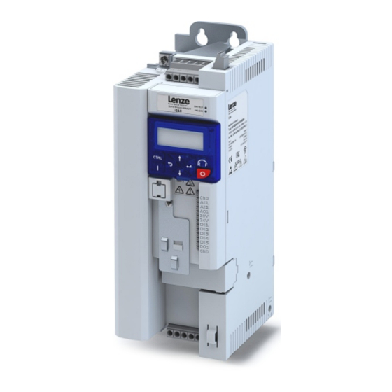
i510 cabinet frequency inverter
0.25 ... 15 kW
Operating instructions i510 cabinet frequency inverter | 1
Advertisement
Table of Contents

Related Manuals for Lenze I51AE B Series


Summary of Contents for Lenze I51AE B Series
- Page 1 Operating instructions i510 cabinet frequency inverter | 1 Operating instructions Home General information Safety instructions Technical data Mechanical installation Electrical installation Commissioning Troubleshooting Disposal i510 cabinet frequency inverter 0.25 ... 15 kW © 01/2023 · EN · www.Lenze.com...
-
Page 2: General Information
Network status LEDs Inverter status LEDs Network shield connection, Option Selector CANopen/Modbus Internal interface Diagnostic module Control terminals Basic I/O Shielding of control connections IT screw X105 Motor connection © 01/2023 · EN · www.Lenze.com... -
Page 3: Application As Directed
The complete documentation, further • The cables must be installed in accordance with EN IEC 60204-1 or US National Electrical information and tools regarding Lenze products can be found on the Internet: Code NFPA 70/Canadian Electrical Code C22.1. -
Page 4: Identification Of The Products
3/PE AC 400 V Application area [kW] 3/PE AC 480 V Default parameter setting: Region EU (50- 0.25 Hz networks) 0.37 Default parameter setting: Region US (60- Hz networks) 0.55 0.75 © 01/2023 · EN · www.Lenze.com... - Page 5 Indicates an extremely hazardous situation. If this instruction is ignored, serious, irreversible injury or deadly injuries may result. NOTE Indicates a material hazard. If this instruction is ignored, damage to property may result. © 01/2023 · EN · www.Lenze.com...
-
Page 6: Basic Safety Instructions
- They are familiar with installing, mounting, commissioning, and operating the product. - They have the corresponding qualifications for their work. - They know and can apply all regulations for the prevention of accidents, directives, and laws applicable at the place of use. © 01/2023 · EN · www.Lenze.com... - Page 7 In the event of a short circuit of two power transistors, a residual movement of up to 180°/ number of pole pairs on the motor may occur (e.g. 4-pole motor): Residual movement max. 180 °/2 = 90°). © 01/2023 · EN · www.Lenze.com...
-
Page 8: Technical Data
Heavy Duty: 200 % for 3s, 150 % for 60s Overload capacity Light Duty 167 % for 3 s, 125 % for 60 s Further standards and operating conditions can be found in the project planning documents. © 01/2023 · EN · www.Lenze.com... -
Page 9: Mechanical Installation
(30 lb-in) I51AE255 ... I51AE311 (optional accessories) ❶ ❷ ❸ 2 Nm (17.7 lb-in) M4x12 I51BE275 ... I51BE311 (optional accessories) ❶ ❷ ❸ 2 Nm (17.7 lb-in) TX20 © 01/2023 · EN · www.Lenze.com... - Page 10 4x M5 >50 >100 I51BExxxF 3 ... 4 1.35 2x M5 >50 >50 I51AExxxF 4x M5 >50 >100 I51AExxxF 7.5 ... 11 4x M5 >50 >100 I51BExxxF 7.5 ... 11 4x M5 >50 >100 © 01/2023 · EN · www.Lenze.com...
-
Page 11: Electrical Installation
• Before connection to an IT system be absolutely sure to remove the screws marked on the product with "IT". I51AE155 ... I51AE222 I51AE230 ... I51AE311 I51AE125 ... I51AE137 I51BE230 ... I51BE240 I51BE275 ... I51BE311 TX10 TX10 TX10 TX10 TX10 © 01/2023 · EN · www.Lenze.com... -
Page 12: Connection Diagram
Mounting plate with (alternatively: shield connection on an conductive surface optional motor shield plate) Low-capacitance motor cable C-core/core/C-core/shield < 75/150 pF/m ≤ 2.5 mm² (≥ AWG 14) C-core/core/C-core/shield < 150/300 pF/m ≥ 4 mm² (≤ AWG 12) " © 01/2023 · EN · www.Lenze.com... - Page 13 Max. short circuit current (SCCR) Circuit breaker Characteristic B, C Max. rated current Max. short circuit current (SCCR) Residual current device (RCD) ≥ 30 mA, type B * Overload time = 3 s, recovery time = 12 s © 01/2023 · EN · www.Lenze.com...
- Page 14 Rated data (light duty) I51AE Inverter 125D 137D 155D 175D 211D 215D 222D 240C 255C Rated power Rated output current (4 kHz) 20.6 27.6 Max. output current * * Overload time = 3 s, recovery time = 12 s © 01/2023 · EN · www.Lenze.com...
- Page 15 137F 155F 175F 211F 215F 222F 230F 240F 255F Rated power Rated output current (4 kHz) 11.9 15.6 Max. output current * 14.6 * Overload time = 3 s, recovery time = 12 s © 01/2023 · EN · www.Lenze.com...
- Page 16 Rated data (light duty) I51AE I51BE I51AE I51BE Inverter 275F 311F Rated power Rated output current (4 kHz) 12.7 14.8 Max. output current * * Overload time = 3 s, recovery time = 12 s © 01/2023 · EN · www.Lenze.com...
- Page 17 Inverter 137F 155F 175F 211F 215F 222F 230F 240F 255F Rated power Rated output current (4 kHz) Max. output current * 12.6 16.4 * Overload time = 3 s, recovery time = 12 s © 01/2023 · EN · www.Lenze.com...
- Page 18 Rated data (light duty) I51AE I51BE I51AE I51BE Inverter 275F 311F Rated power Rated output current (4 kHz) 10.8 13.2 Max. output current * * Overload time = 3 s, recovery time = 12 s © 01/2023 · EN · www.Lenze.com...
- Page 19 10 V output Primarily for the supply of a potentiometer (1 ... 10 kΩ). Max. 10 mA 24 V output Primarily for the supply of digital inputs. Max. 100 mA for DO1 and 24 V output © 01/2023 · EN · www.Lenze.com...
- Page 20 Max. cable cross-section mm² Stripping length Required tool 0.4 x 2.5 Normally-open contact Application Normally-closed contact Common contact AC 240 V/3 A Max. switching voltage/switching DC 24 V/2 A current DC 240 V/0.16 A © 01/2023 · EN · www.Lenze.com...
- Page 21 Connect the resistor to terminals TB/CH and TA/CL. • Node address = setting in P510.01 • Baud rate = setting in P510.02 • For Modbus RTU, the baud rate and parity are detected automatically. © 01/2023 · EN · www.Lenze.com...
-
Page 22: Initial Switch-On
• The analog input X3/AI1 must not be wired or connected to GND. 1. Switch on mains voltage. 2. Check readiness for operation. 3. Observe LED status displays “RDY” and “ERR” on the inverter front panel. © 01/2023 · EN · www.Lenze.com... -
Page 23: Important Notes
SMART Keypad App system movements. The Lenze SMART Keypad App for Android or iOS allows you to diagnose and parameterize an Possible consequences: Death, severe injuries, or damage to property inverter. A WLAN module on the inverter is required for communication. - Page 24 • The motor must be at standstill before parameters can be changed or confirmed. • The settings are saved temporarily until the motor is switched off again. Press and hold the enter key for 3 s to save the settings permanently. © 01/2023 · EN · www.Lenze.com...
- Page 25 2. Change the frequency setpoint using the up arrow key or the down arrow key. 3. Press the stop key to stop the motor. Reverse rotating direction: 1. Press the R/F key. 2. Press the enter key to confirm the reversal of rotating direction. © 01/2023 · EN · www.Lenze.com...
- Page 26 P430.02 P430.02 P210.00 Time 3. Save settings: Press and hold the enter key for 3 s. 4. With the wiring shown on the right, the inverter can be operated using the control terminals. © 01/2023 · EN · www.Lenze.com...
- Page 27 Freq. preset 1 20.0 Hz Preset value 2 P450.02 Freq. preset 2 40.0 Hz Preset value 3 P450.03 Freq. preset 3 50.0 Hz / 60.0 Hz* * Depending on whether device is for 50-Hz mains or 60-Hz mains © 01/2023 · EN · www.Lenze.com...
- Page 28 Group 0 contains the configurable favorites that are also contained in the groups 1 to 4. In the default setting these are the most common parameters for the solution of typical applications. © 01/2023 · EN · www.Lenze.com...
- Page 29 Device for 60-Hz mains: 60 Hz * P220.00 Acceleration 1 0.0 ... 5.0 ... 3600.0 s Acceleration time 1. P221.00 Deceleration 1 0.0 ... 5.0 ... 3600.0 s Deceleration time 1 * Default setting dependent on the model © 01/2023 · EN · www.Lenze.com...
- Page 30 Setting of the rated motor current according to motor nameplate. P324.00 Max. current 0.0 ... 200.0 ... 3000.0 % Maximum overload current of the inverter. With regard to rated motor current (P323.00). * Default setting dependent on the model © 01/2023 · EN · www.Lenze.com...
- Page 31 Assignment of a trigger to the “Run reverse (CCW)” function. P400.09 Run reverse Not connected Trigger = TRUE: Let motor rotate backward. Trigger = FALSE: Stop motor. * Default setting dependent on the model © 01/2023 · EN · www.Lenze.com...
- Page 32 Assignment of a trigger to digital output 1. P420.02 DO1 function Release brake [115] Trigger = FALSE: X3/DO1 set to LOW level. Trigger = TRUE: X3/DO1 set to HIGH level. * Default setting dependent on the model © 01/2023 · EN · www.Lenze.com...
- Page 33 0.0 ... 50.0 | 60.0 ... 599.0 Hz * Parameterizable frequency setpoints (preset 3). P450.04 Freq. preset 4 0.0 ... 0.0 ... 599.0 Hz Parameterizable frequency setpoints (preset 4). * Default setting dependent on the model © 01/2023 · EN · www.Lenze.com...
- Page 34 • Setting is not effective in the operating mode P301.00 = “CiA: Velocity mode [2]”. © 01/2023 · EN · www.Lenze.com...
- Page 35 0 ... 1 • The motor equivalent circuit diagram data and controller settings are calculated on the basis of the currently set rated motor data. • The motor is not energized. © 01/2023 · EN · www.Lenze.com...
- Page 36 • When the inverter is switched on, all parameters are automatically loaded from the user memory of the memory module to the RAM memory of the inverter. Off/ready Only status feedback © 01/2023 · EN · www.Lenze.com...
-
Page 37: Troubleshooting
2. Via error reset signal (P400.04, default setting of digital input 2). • Prerequisite: Cause of error has been eliminated and no blocking time is active. • The error is reset if a signal is applied to digital input 2. © 01/2023 · EN · www.Lenze.com... -
Page 38: Error Codes
6280 Trigger/functions connected incorrectly Trouble • With keypad or network control, the two functions “Inverter enable” (P400.01) and “Run” (P400.02) can also be set to “Constant TRUE [1]” to start the motor. © 01/2023 · EN · www.Lenze.com... - Page 39 Automatic start disabled Trouble • Deactivate start command and reset error. FF85 Keypad full control active Warning • Press the CTRL key to exit control mode. © 01/2023 · EN · www.Lenze.com...
-
Page 40: Led Status
Inverter enabled, warning active. The motor rotates according to the specified setpoint or blinking fast quick stop active. Inverter enabled, quick stop active as response to a fault. blinking © 01/2023 · EN · www.Lenze.com... - Page 41 LED status Support Support Further information can be found on the online page www.lenze.com/product-information The material number of the product can be found on the nameplate. © 01/2023 · EN · www.Lenze.com...
- Page 42 More detailed information on disposal can be obtained from the corresponding specialist firms and the competent authorities. The packaging of the component must be disposed of separately. Paper, cardboard and plastics must be recycled. © 01/2023 · EN · www.Lenze.com...
Need help?
Do you have a question about the I51AE B Series and is the answer not in the manual?
Questions and answers