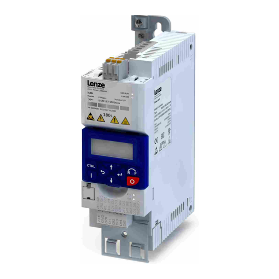
Page 1
Operating Instructions | EN Inverter Inverter i510-Cabinet 0.25 ... 15 kW As easy as that.
Page 2
Overview Overview Hardware overview of the inverter PE connec on X100 Mains connec on/DC bus Relay output IT screw from 0.55 kW X216 Network Memory module Op on Netword status Inverter status Shield connec on Op on Toggle switch Interface CANopen/Modbus Diagnos c module Control terminals...
Contents Contents 1 General information .....................4 Commissioning......................15 1.1 Target group ........................4 7.1 Keypad module ......................15 1.2 Application as directed ....................4 7.1.1 Functions of the keys ..................16 1.3 Device-specific standards and directives .................4 7.1.2 Example of the keypad handling ..............16 1.4 Relevant standards and directives for the operator ............4 7.1.3 Quick commissioning - terminal control ............16 1.5 Identification of the products ..................5...
• The test voltage for insulation resistance tests between a control potential of 24 V and PE The complete documentation, further information and tools regarding Lenze products can be must be measured in accordance with EN 61800-5-1.
Safety instructions Identification of the products Safety instructions Basic safety measures 5 1 A E x 1 x x x x xxxx Product type Inverter Disregarding the following basic safety measures may lead to severe personal injury and Product family i500 damage to property! Product i510 •...
Safety instructions Layout of warning notices Residual hazards Safety instructions protect against injury to persons or damage to property. The measures The user must take the residual hazards mentioned into consideration in the risk assessment described for the prevention of hazards must be complied with. for his/her machine/system.
Technical data Technical data Connection to the IT system Standards and operating conditions NOTE Conformities 2014/35/EU, 2014/30/EU TR TC 004/2011, TP TC 020/2011 Electrical voltage RoHS 2 2011/65/EU Approvals UL 61800-5-1, CSA 22.2 No. 274 Internal components have ground potential if the IT screws are not removed. Energy efficiency Class IE2 EN 50598-2...
Electrical installation Electrical installation EMC-compliant installation The drive system (inverter and drive) complies with the EMC Directive 2014/30/EU if it is General overview of the connections installed according to the guidelines for CE-typical drive systems. The connection diagram is considered exemplary for all voltage and power classes. Deviating The structure in the control cabinet must support the EMC-compliant installation with mains connection diagrams can be found in the corresponding chapters.
Electrical installation Control terminals Relay output Basic I/O The relay is not suitable for direct switching of an electromechanical holding brake. Use a corresponding suppressor circuit in case of an inductive or capacitive load. Input/output Terminal X3 Information Inverter [kW] 0.25 ... 15 Digital inputs DI1, DI2, DI3, DI4, DI5 DI3/DI4 can be optionally used as frequency or encoder input.
Initial switch-on Initial switch-on Commissioning DANGER DANGER Electrical voltage Electrical voltage Incorrect wiring can cause unexpected states during the commissioning phase. Incorrect wiring can cause unexpected states during the commissioning phase. ► Wiring must be complete and correct. ► Wiring must be complete and correct. ►...
Commissioning 7.1.1 Functions of the keys 7.1.3 Quick commissioning - terminal control The following quick overview with graphical parameter representation is sufficient for Actuation Action commissioning many applications with terminal control. Further setting options are described Press briefly • Navigate in the Menu Change parameters in this document or in the commissioning document. 1.
DO1 activated at Digital output 1 *P420.02 Release brake GND for analog and digital signals Commissioning and diagnostics can be carried out with the EASY starter engineering tool. http://www.Lenze.com Relay NO contact Relay activated at *P420.01 Ready for operation Relay common contact...
Commissioning The most important parameters at a glance This chapter contains the most important parameters and selections. You can find a detailed description in the commissioning document. http://www.Lenze.com The parameters are divided into the following function groups: • Pxxx.xx group 0: Favorites •...
Page 19
P300.00 Motor ctrl mode Servo control (SC ASM) This control mode is used for servo control of an asynchronous motor. This motor control mode is described in the commissioning manual. Lenze Doc Finder Sensorless control This control type is used for the sensorless control of a synchronous motor. This motor control mode is described in the commissioning manual.
Page 20
Commissioning Possible settings/ Display code Name Keypad code Information value ranges P323.00 Motor current 0.001 ... 1.700 ... 500.000 A * Setting of the rated motor current according to motor nameplate. With regard to rated motor current (P323.00) P324.00 Max current 0.0 ...
Page 21
Commissioning Possible settings/ Display code Name Keypad code Information value ranges P400.18 Setp: Preset B0 Digital input 4 [14] Assignment of a trigger to the “Activate preset (bit 0)” function.Bit with the value 20 for the bit-coded selection and activation of a configured setpoint (preset value).
Commissioning Possible settings/ Display code Name Keypad code Information value ranges P440.02 AO1 function Output frequency Actual output frequency (resolution: 0.1 Hz). Frequency setpoint Actual frequency setpoint (resolution: 0.1 Hz). Analog input 1 Input signal from analog input 1 (resolution: 0.1 %). P440.03 AO1 min.
Commissioning 7.4.4 Group 7: Additional functions Display code Name Possible settings Keypad code Information Off / ready P700.01 Device commands: Only status feedback Load default settings On / start 1 = reset all parameters in the RAM memory of the inverter to the default setting that is stored in the inverter firmware. •...
Troubleshooting Troubleshooting Error message If an error is pending, the keypad shows the following information. 1 = error text 2 = error type F = fault T = trouble W = warning 3 = error code (hexadecimal) Faults (F) and trouble (T) are displayed continuously. The inverter is disabled. Warnings (W) are displayed every 2 seconds for a short time.
Troubleshooting Error codes Blocking time Error code Description Classification Remedy Reset possible 2250 CiA: Continuous overcurrent (inside the device) Error • Check motor and wiring for short circuits. • Check brake resistor and wiring. • Check motor switching. • Check motor data settings. 2320 Short circuit or earth leakage on the motor side Error •...
Page 26
Troubleshooting Blocking time Error code Description Classification Remedy Reset possible 4210 PU: Overtemperature fault Error • Check mains voltage. • Ensure sufficient cooling of the device (heatsink temperature displayed in P117.01). • Clean fan and ventilation slots. Replace fan if necessary. •...
Fundamental information on project planning and ordering the product Commissioning document Fundamental information for the installation and commissioning of the pro- duct Mounting instructions Fundamental information on mounting the product The documents can be found in the Lenze Doc Finder. Operating instructions I510-Cabinet...
Need help?
Do you have a question about the i500 Series and is the answer not in the manual?
Questions and answers