Table of Contents
Advertisement
Quick Links
Advertisement
Table of Contents

Related Manuals for Datalogic DS41-X0


Summary of Contents for Datalogic DS41-X0
- Page 1 DS41 Installation Manual...
- Page 2 DS41 INSTALLATION MANUAL...
- Page 3 Quality Assurance Supervisor Product names mentioned herein are for identification purposes only and may be trademarks and or registered trademarks of their respective companies. Datalogic S.p.A. reserves the right to make modifications and improvements without prior notification. © - 1997 Datalogic S.p.A.
-
Page 4: Table Of Contents
CONTENTS General View..................v SAFETY PRECAUTIONS..............vii Laser Safety..................vii Standard Regulations.................vii Power Supply ..................ix GENERAL FEATURES ..............1.1 Introduction ..................1.1 Description ..................1.2 Available Models ................1.4 Accessories..................1.4 INSTALLATION................2.1 Package Contents................2.1 Guide To Installation ................2.2 Opening The Device ................2.3 Main Interface Selection ..............2.4 Mechanical Installation..............2.5 JBOX Installation ................2.6 2.6.1... - Page 5 READING FEATURES ..............3.1 Step Ladder Mode................3.1 Picket Fence Mode ................3.2 Performance ..................3.3 Reading Diagrams ................3.4 MAINTENANCE................4.1 Cleaning ...................4.1 TECHNICAL FEATURES ..............5.1...
-
Page 6: General View
DS41 General View Figure A Cable with 25-pin connector Warning and Classification labels Mounting holes Warning label Laser active LED Power on LED Laser beam output window Successful read LED Presence sensor active LED 11 Accessory mounting holes Data transmission LED... - Page 7 DS41 General View Figure B Cable with junction box Warning and Classification labels Mounting holes Warning label Laser active LED Power on LED Laser beam output window Successful read LED Presence sensor active LED 11 Accessory mounting holes Data transmission LED...
-
Page 8: Safety Precautions
SAFETY PRECAUTIONS LASER SAFETY The following information is provided to comply with the rules imposed by international authorities and refers to the correct use of the DS41 scanner. Standard Regulations This scanner utilizes a low-power laser diode. Although staring directly at the laser beam momentarily causes no known biological damage, avoid staring at the beam as one would with any very strong light source, such as the sun. - Page 9 Warning labels indicating exposure to laser light and the device classification are applied onto the body of the scanner (Figure A, DATALOGIC S.p.A. Via Candini, 2 40012 LIPPO DI CALDERARA (BO) ITALY Model No. Serial No. LISTED 45AF I.T.E. Volt Amp.
-
Page 10: Power Supply
READ THIS INFORMATION BEFORE INSTALLING THE PRODUCT - This product is intended to be installed by Qualified Personnel only. - Model DS41-X0: This device is intended to be supplied by a UL Listed Direct Plug-in Power Unit marked "Class 2", rated 10-30 V, minimum 0.46 A. - Page 11 This page is intentionally left blank.
-
Page 12: General Features
C Programmability The DS41 belongs to the generation of Datalogic scanners that operate under the 'C' programming environment which is a recognized industry standard. If your requirements are not met by the Standard Application Program, Custom Application Programs can be developed by your local Datalogic distributor. -
Page 13: Description
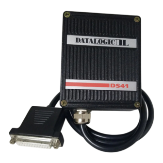
DS41 DATALOGIC DESCRIPTION Some of the main features of this scanner are given below: • very high scanning speed (800 scans/sec). • raster versions available. • completely configurable from host computer. • 2 serial communication interfaces; one can be set as RS232, RS485, or 20 mA C.L., and the other is an RS232 auxiliary interface. - Page 14 DATALOGIC DS41 Electrical connection is provided through a cable on the side of the reader; this cable is terminated with a 25-pin connector (25-pin connector models, see paragraph 1.3, Figure A, ) or by a junction box (junction box models, see paragraph 1.3, Figure B,...
-
Page 15: Available Models
DS41 DATALOGIC AVAILABLE MODELS The DS41 scanner is available in versions that differ in regard to the following parameters: • Resolution • Termination of the cable • Distance between the scan beams (raster models only) • DSP or NPP The following models are therefore available:... -
Page 16: Installation
DATALOGIC DS41 2 INSTALLATION PACKAGE CONTENTS Verify that the DS41 reader and all the parts supplied with the equipment are present and intact when opening the packaging; the list of parts includes: DS41 reader with cable Installation manual Barcode test chart(s) -
Page 17: Guide To Installation
DS41 DATALOGIC GUIDE TO INSTALLATION The following can be used as a checklist to verify all of the steps necessary for complete installation of the DS41 scanner. 1) Read all information in the section "Safety Precautions" at the beginning of this manual. -
Page 18: Opening The Device
DATALOGIC DS41 OPENING THE DEVICE Before installing the DS41 it may be necessary to open the scanner to select the interface required. WARNING The scanner must be disconnected from the power supply during this operation. Refer to the following instructions and diagram below when opening the reader: •... -
Page 19: Main Interface Selection
DS41 DATALOGIC MAIN INTERFACE SELECTION One of the following interface types can be selected to connect the main interface of the DS41 to the host computer. EIA RS232 20 mA CURRENT LOOP EIA RS485 POLLED EIA RS485 NON POLLED To select the interface type, position the jumper block as indicated in the... -
Page 20: Mechanical Installation
DATALOGIC DS41 MECHANICAL INSTALLATION DS41 can be installed to operate in different positions. The four screw holes (M4 x 5) on the body of the reader are for mechanical fixture (Figure A, The diagram below gives the overall dimensions of the scanner and may be used for its installation. -
Page 21: Jbox Installation
DS41 DATALOGIC JBOX INSTALLATION JBOX provides a passive connection between your scanner and the outside world in a fast and practical way. It represents an alternative to the 25-pin connector models. Figure 2.5 shows the basic layout of DS41 using the junction box. - Page 22 DATALOGIC DS41 JBOX is designed to be mounted to a panel of metal, plastic or other appropriate material using the mounting screws provided in the package. To do this: 1) Open the junction box by unscrewing the 4 cover screws.
-
Page 23: Electrical Connections For Jbox
DS41 DATALOGIC 2.6.2 Electrical Connections for JBOX The connection and wiring procedure for JBOX is described as follows: 1) Open the junction box by unscrewing the 4 cover screws. 2) Pass all System cables through the glands in the junction box housing. - Page 24 DATALOGIC DS41 JBOX pinout for DS41 Name SGND SGND CHASSIS Figure 2.9 - JBOX connector and pinout SGND SGND n.c. n.c. To allow connection of an NEC Class 2 SGND SGND Power Unit, use a correct female plug NOREAD+ adapter.
- Page 25 DS41 DATALOGIC 4) After wiring the junction box and while the scanner is unplugged from the power supply, place the Scanner cable so that the rubber seal fits into the cutout in the housing of the junction box and plug the 24-pin connector into connector J1 on the PCB inside the junction box as shown in figure 2.11.
-
Page 26: Electrical Connections For 25-Pin Models
DATALOGIC DS41 ELECTRICAL CONNECTIONS FOR 25-PIN MODELS 25-pin connector models (see paragraph 1.3) are equipped with a cable terminated by a 25-pin D-sub connector for connection to the power supply and input/output signals. The details of the connector pins are indicated in the following table: Figure 2.12 - 25-pin D-sub connector... -
Page 27: Power Supply
DS41 DATALOGIC 2.7.1 Power supply Power can be supplied to the scanner through the pins provided on the 25- pin connector used for communication with the host (Figure 2.13): USER INTERFACE DS41 V+ (10 - 30 Vdc) SGND Earth Ground... -
Page 28: Main Serial Interface
EIA RS232 EIA RS485 NON POLLED EIA RS485 POLLED (for connection with a Datalogic multiplexer) 20 mA PASSIVE CURRENT LOOP DS41 automatically recognizes the type of interface selected at each power on of the scanner. If the recognized interface type is not compatible with the current communication handshaking, then the system forces the XON/XOFF protocol. -
Page 29: Rs232 Interface
DS41 DATALOGIC RS232 interface The serial interface is used in this case for point to point connections; it handles communication with the host computer and allows both transmission of code data and the configuration of the scanner. This is the default interface. -
Page 30: Rs485 Non Polled Interface
DATALOGIC DS41 Figure 2.16 - RS232 control signals The RTS232 and CTS232 signals control data transmission and synchronize the connected devices. If the RTS/CTS handshaking protocol is enabled, the DS41 activates the RTS232 output to indicate a message is to be transmitted. The receiving unit activates the CTS232 input to enable the transmission. -
Page 31: Rs485 Polled Interface
The RS485 POLLED interface is a Half Duplex (3 wires + shield) interface. The POLLED configuration can be used for multidrop connections with a Datalogic multiplexer or it can also be used for a master-slave layout (see paragraph 2.9.1). The following pins of the 25-pin connector are used for RS485 POLLED... - Page 32 DATALOGIC DS41 For this interface type, the multidrop address must also be set on the DIP switch as shown in the figure below. Record this information for further setup of the multidrop line. Figure 2.19 - DIP switch for multidrop address selection...
- Page 33 DS41 DATALOGIC The figure below shows a multidrop configuration with DS41 scanners connected to a Multiplexer. 120 Ohm max. 2 m. DS41 (up to 31) DS41 max. 1200 m. TX485+ DS41 TX485- SGND CHASSIS three wires + shield +RTX485 -RTX485...
-
Page 34: Ma Current Loop Interface
DATALOGIC DS41 20 mA current loop interface The DS41 only supports passive type current loop connections. The following pins of the 25-pin connector are used: Name Function CLIN- Current Loop Input (-) CLIN+ Current Loop Input (+) CLOUT- Current Loop Output (-) -
Page 35: Auxiliary Rs232 Interface
DS41 DATALOGIC 2.7.3 Auxiliary RS232 interface The auxiliary serial interface is used exclusively for RS232 point to point connections. The parameters relative to the auxiliary interface (baud rate, data bits, etc.) as well as particular operating modes such as local echo can be defined using the WINHOST utility program or Host Mode programming. -
Page 36: Inputs
DATALOGIC DS41 2.7.4 Inputs The inputs available on the DS41 scanner are the pins relative to the code presence sensor, as indicated below: Name Function Presence sensor (input+) Presence sensor (input-) The inputs indicated are always used to connect the code presence sensor which tells the scanner to scan for a code. - Page 37 DS41 DATALOGIC Vext 30 Vdc max. PRESENCE SENSOR DS41 + 5V Signal Ground Figure 2.25 - Input PNP command using external power DS41 PRESENCE SENSOR + 5V Signal Figure 2.26 - Input PNP command using DS41 power The electrical features are given below:...
-
Page 38: Outputs
DATALOGIC DS41 2.7.5 Outputs In addition to the pins relative to the communication interfaces as described in the previous paragraphs, the following pins are present on the 25-pin connector of the scanner: Name Function NO READ+ No read output (+) -
Page 39: Positioning
DS41 DATALOGIC The WRONG output is used either for "Verifier" mode or for PCS control (PCS control is available for DSP models only, see paragraph 1.3). For Verifier this output activates when the decoded code does not correspond to the one set in the configuration. For PCS this output activates when the PCS level is below the threshold value. - Page 40 DATALOGIC DS41 Figure 2.30 - Pitch angle The Skew angle is represented by the value S in Figure 2.31. Position the reader to assure at least 10° for the Skew angle. This avoids the direct reflection of the laser light emitted by the DS41.
-
Page 41: Typical Layouts
DS41 DATALOGIC TYPICAL LAYOUTS The DS41 barcode reader was specifically designed for industrial applications. A typical use is real time identification of moving objects on conveyor belts. A photoelectric sensor used as a code presence sensor signals when an object enters the scanner reading zone (see Figure 2.33). -
Page 42: Master-Slave
DATALOGIC DS41 2.9.1 Master-slave The master-slave layout is used to collect data from several scanners to build a multi-sided reading system; there can be one master and up to 5 slaves connected with the RS485 polled mode on the main serial interface. -
Page 43: Local Echo
DS41 DATALOGIC 2.9.2 Local echo In local echo mode data is transmitted on the auxiliary interface as well as on the main interface. Host Mode programming can be accomplished either through the main interface or the auxiliary interface in local echo mode. -
Page 44: Reading Features
DATALOGIC DS41 3 READING FEATURES The number of reads performed by the DS41 and therefore the decoding capacity, is influenced by the following parameters: • number of scans per second • code motion speed • label dimensions • scan direction in respect to code motion At least 5 scans during the code passage should be allowed to ensure a successful read. -
Page 45: Picket Fence Mode
DS41 DATALOGIC For example, the DS41 (800 scans/sec.), for a 25 mm high code moving at 1250 mm/s performs: [(25/1250) * 800] - 2 = 14 effective scans. PICKET FENCE MODE Laser Beam Code motion moving at LS speed DS41 Figure 3.2 - "Picket Fence"... -
Page 46: Performance
25 °C ambient temperature, depending on the conditions in the notes under each diagram. If standard devices do not satisfy specific requirements, contact your nearest Datalogic distributor, supplying code samples, to obtain complete information on the reading possibilities. Reading features - 3.3... -
Page 47: Reading Diagrams
DS41 DATALOGIC READING DIAGRAMS DS41-1x and DS41-6x (Standard Resolution, 800 scans/s) NOTE: (0,0) IS THE CENTER OF THE LASER BEAM OUTPUT WINDOW 0.30 mm 0.20 mm CONDITIONS: Code Interleaved 2/5 or Code 39 0.90 "Pitch" angle 0° "Skew" angle 10°... - Page 48 DATALOGIC DS41 DS41-1x and DS41-6x (Standard Resolution, 800 scans/s) NOTE: (0,0) IS THE CENTER OF THE LASER BEAM OUTPUT WINDOW 0.50 mm 0.60 mm 0.80 mm 1.00 mm CONDITIONS: Code Interleaved 2/5 or Code 39 0.90 "Pitch" angle 0° "Skew" angle 10°...
- Page 49 DS41 DATALOGIC DS41-2x and DS41-7x (Very High resolution, 800 scans/s) NOTE: (0,0) IS THE CENTER OF THE LASER BEAM OUTPUT WINDOW 0.20 mm 0.15 mm 0.10 mm CONDITIONS: Code Interleaved 2/5 or Code 39 0.90 "Pitch" angle 0° "Skew" angle 10°...
-
Page 50: Maintenance
DATALOGIC DS41 4 MAINTENANCE CLEANING Clean the laser beam output window periodically for continued correct operation of the reader. Dust, dirt, etc. on the window may alter the reading performance. Repeat the operation frequently in particularly dirty environments. Use soft material and alcohol to clean the window and avoid any abrasive substances. - Page 51 DS41 DATALOGIC This page is intentionally left blank. 4.2 - Maintenance...
-
Page 52: Technical Features
DATALOGIC DS41 5 TECHNICAL FEATURES DSP MODELS NPP MODELS (Note 1) (Note 1) ELECTRICAL FEATURES INPUT POWER Supply voltage 10 to 30 Vdc Power consumption max. SERIAL INTERFACES MAIN RS232, RS485 Non Polled, RS485 Polled, 20 mA Passive C. L. - Page 53 DS41 DATALOGIC DSP MODELS NPP MODELS (Note 1) (Note 1) SOFTWARE FEATURES Up to 22 readable symbologies including: READABLE CODE SYMBOLOGIES • • Code 93 (Standard and Full ASCII) • • EAN/UPC (including Add-on 2 and Add-on 5) • •...
Need help?
Do you have a question about the DS41-X0 and is the answer not in the manual?
Questions and answers