Table of Contents
Advertisement
Advertisement
Table of Contents
Troubleshooting

Related Manuals for Datalogic DS1500


Summary of Contents for Datalogic DS1500
- Page 1 DS1500 Reference Manual...
- Page 2 DATALOGIC S.p.A. Via Candini 2 40012 - Lippo di Calderara di Reno Bologna - Italy DS1500 Reference Manual Ed.: 11/2007 ALL RIGHTS RESERVED Datalogic reserves the right to make modifications and improvements without prior notification. Datalogic shall not be liable for technical or editorial errors or omissions contained herein, nor for incidental or consequential damages resulting from the use of this material.
-
Page 3: Table Of Contents
1.5.2 Activating Test Operating Mode... 5 Accessories... 6 INSTALLATION... 7 Package Contents... 7 Mechanical Installation... 8 2.2.1 Mounting DS1500 ... 10 Electrical Connections ... 11 2.3.1 Power Supply... 12 2.3.2 Main Serial Interface ... 12 2.3.3 Auxiliary RS232 Interface ... 17 2.3.4... - Page 4 READING FEATURES ... 28 Advanced Code Builder (ACB)... 28 3.1.1 Important ACB Reading Conditions ... 29 3.1.2 Tilt Angle Improvement with ACB ... 30 Linear Code Reading ... 30 3.2.1 Step-Ladder Mode ... 31 3.2.2 Picket-Fence Mode ... 32 Performance ... 33 Reading Diagrams ...
-
Page 5: References
“User” or “Operator” refers to anyone using a DS1500. “Device” refers to the DS1500. “You” refers to the System Administrator or Technical Support person using this manual to install, mount, operate, maintain or troubleshoot a DS1500. REFERENCE DOCUMENTATION The documentation related to the DS1500 management is listed below: •... -
Page 6: Safety Regulations
LASER SAFETY The following information is provided to comply with the rules imposed by international authorities and refers to the correct use of the DS1500 scanner. Standard Regulations This scanner utilizes a low-power laser diode. Although staring directly at the laser beam momentarily causes no known biological damage, avoid staring at the beam as one would with any very strong light source, such as the sun. -
Page 7: Power Supply
POWER SUPPLY This device is intended to be supplied by a UL Listed or CSA Certified Power Unit with «Class 2» or LPS power source, which supplies power directly to the scanner via the 15-pin connector. Warning and Device Class Label... -
Page 8: Ce Compliance
CE COMPLIANCE Warning: This is a Class A product. In a domestic environment this product may cause radio interference in which case the user may be required to take adequate measures. WEEE COMPLIANCE Information for the user in accordance with the European Commission Directive 2002/96/EC At the end of its useful life, the product marked with the crossed out wheeled wastebin must be disposed of separately from urban waste. - Page 9 Benutzerinformation bezüglich Richtlinie 2002/96/EC der europäischen Kommission Am Ende des Gerätelebenszyklus darf das Produkt nicht über den städtischen Hausmüll entsorgt werden. Eine entsprechende Mülltrennung ist erforderlich. Beseitigung des Produkts entsprechend der Richtlinie: • verhindert negative Auswirkungen für die Umwelt und die Gesundheit der Menschen •...
-
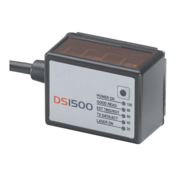
Page 10: General View
GENERAL VIEW Laser Beam Output Window Test Key Power On LED Good Read LED DS1500 Figure A External Trigger/Ready LED Tx Data/Active LED Laser On LED Warning and Device Class Label Mounting Holes Product Label 15-pin D-sub High-density Male Connector... -
Page 11: Guide To Installation
2.5 and 3.4. 4) Make electrical connections to your DS1500 scanner by either: Connecting the test cable to the DS1500 scanner as described in par.2.4. Providing correct and complete system cabling according to the signals necessary for the layout of your application. -
Page 13: Introduction
DS1500 installation and configuration is easy and simple thanks to the compact size and to the new test operating mode with bar graph. Test Mode is activated by means... -
Page 14: Applications
ATL (Automated Tape Library), packaging machines. MODEL DESCRIPTION The following scheme illustrates the model description of the DS1500 scanner: DS1500 - X X 0 0 Optical Resolution 1 = Standard Resolution 2 = High Resolution The following tables display the scanner reading performance. -
Page 15: Indicators
INTRODUCTION INDICATORS The five LEDs indicate the following: Standard Mode Indicates the reader POWER ON (green) is connected to the (Figure A, 3) power supply. Indicates GOOD READ (green) possibility (Figure A, 4) successful barcode reading. Indicates EXT TRIG/RDY (yellow) trigger (Figure A, 5) Refer to par. -
Page 16: Test Key Functioning
If the Test key is released before the TX Data/ACT LED is off, the Restoring Dual RS232 is not executed. To restart the procedure, it is first necessary to switch off the DS1500 scanner. The Restore Dual RS232 is not permanently saved. -
Page 17: Activating Test Operating Mode
Ext Trig/RDY LEDs turn off the Test Mode has been disabled. The previous operating mode will be restored. If the scanner has been configured in Test Mode via software, a first Test key press will produce no effect. A second Test key press will exit the Test Mode and enable the Default On Line mode. -
Page 18: Accessories
NOTE You must not be in Test Mode activated by Test Key when configuring DS1500 parameters. NOTE ACCESSORIES The following accessories are available on request for the DS1500: Name Description CONFIG / DOC PKG DS1500 Manual, Test Chart, other documentation... -
Page 19: Installation
INSTALLATION INSTALLATION PACKAGE CONTENTS Verify that the DS1500 reader and all the parts supplied with the equipment are present and intact when opening the packaging; the list of parts includes: • DS1500 reader with cable • DS1500 Quick Guide •... -
Page 20: Mechanical Installation
DS1500 MECHANICAL INSTALLATION DS1500 can be installed to operate in different positions. The two screw holes (M2 x 4) on the body of the reader are for mechanical fixture (Figure A, 1). The diagrams below give the overall dimensions of the scanner and mounting bracket and may be used for installation. - Page 21 INSTALLATION [0.79] [0.06] [0.98] [0.13] inch [0.47] Figure 3 – Mounting Bracket Overall Dimensions...
-
Page 22: Mounting Ds1500
DS1500 2.2.1 Mounting DS1500 Using the DS1500 mounting bracket you can obtain the most suitable position for the reader as shown in the figure below: Skew Pitch Figure 4 – Positioning with Mounting Bracket... -
Page 23: Electrical Connections
INSTALLATION ELECTRICAL CONNECTIONS All DS1500 models are equipped with a cable terminated by a 15-pin male D-sub high-density connector for connection to the power supply and input/output signals. The details of the connector pins are indicated in the following table. -
Page 24: Power Supply
2.3.1 Power Supply Power can be supplied to the scanner through the pins provided on the 15-pin connector used for communication with the host (Figure 6): DS1500 The power must be 5 Vdc only. It is recommended to connect pin 8 (Protective Earth Ground) to a common earth ground. -
Page 25: Rs232 Interface
The serial interface is used in this case for point-to-point connections; it handles communication with the host computer and allows both transmission of code data and the programming of the scanner. This is the default setting. The following pins are used for RS232 interface connection: It is always advisable to use shielded cables. -
Page 26: Rs485 Full-Duplex Interface
The connector pinout follows: Name TX485+ TX485- RX485+ RX485- SGND DS1500 Figure 8 - RS485 Full-duplex Connections Function RS485 transmit data + RS485 transmit data - RS485 receive data + RS485 receive data - signal ground USER INTERFACE... -
Page 27: Rs485 Half-Duplex Interface
Name RTX485+ RTX485- SGND DS1500 Figure 9 - RS485 Half-duplex Connections This interface is forced by software when the protocol selected is MUX32 protocol. In a Multiplexer layout or for slaves, the Multidrop address must also be set via the serial channel by the WinHost utility or by ESC sequences. - Page 28 Figure 10 shows a multidrop configuration with DS1500 scanners connected to a Multiplexer. To avoid any possible Ground loop, keep the chassis isolated from the Ground. CAUTION This is an example of multidrop wiring. Consult the multiplexer manual for complete wiring instructions.
-
Page 29: Auxiliary Rs232 Interface
WinHost utility program or "Host Mode Programming". The following pins of the 15-pin connector are used to connect the RS232 auxiliary interface: DS1500 Figure 11 - RS232 Auxiliary Interface Connections The Auxiliary RS232 interface is only available when the main interface is RS232. -
Page 30: Code Verifier
Code Verifier If the DS1500 is used as a Code Verifier, it is possible to indicate to the scanner what code to store as the verifier code through the WinHost program, (refer to the WinHost Help On Line). 2.3.4 Inputs... -
Page 31: Outputs
Right event, which activates when the code is correctly decoded. These outputs are both level and pulse configurable. DS1500 7/14 Figure 14 - DS1500 Output Connections max = 40 Vdc I max = 20 mA continuous Function output 1 +... -
Page 32: User Interface
The Auxiliary RS232 interface is only available when the main interface is RS232. NOTE RS232 PC-side connections TXAUX RXAUX SGND EXT TRIG- Test Cable for DS1500 25-pin male connector Name 9-pin D-sub female Power Supply VS (5 Vdc) Power GND DS1500... -
Page 33: Positioning
INSTALLATION POSITIONING The DS1500 scanner is able to decode moving barcode labels at a variety of angles, however significant angular distortion may degrade reading performance. When mounting the DS1500 take into consideration these three ideal label position angles: Pitch 0°, Skew 15° to 30° and Tilt 0°. - Page 34 DS1500 The Tilt angle is represented by the value T in Figure 17. Position the reader in order to minimize the Tilt angle. Figure 17 - Tilt Angle By using the ACB (Advanced Code Builder) software parameter, the tilt angle is less critical and can be decoded even if the scan line doesn’t cross the entire code.
-
Page 35: Typical Layouts
In Local Echo communication mode, data is transmitted on the RS232 auxiliary interface independently from the main interface selection. When On-Line Operating mode is used, the scanner is activated by an External Trigger (photoelectric sensor) when the object enters its reading zone. - Page 36 In this layout the data is transmitted to the Host on the main serial interface. Host Mode programming can be accomplished through the main interface. When On-Line Operating mode is used, the scanner is activated by an External Trigger (photoelectric sensor) when the object enters its reading zone.
-
Page 37: Pass-Through
Pass-through mode allows two or more devices to be connected to a single external serial interface. Each DS1500 transmits the messages received by the Auxiliary interface onto the Main interface. All messages will be passed through this chain to the host. -
Page 38: Rs232 Master/Slave
9 slaves connected together. The Slave scanners use RS232 only on the main and auxiliary serial interfaces. Each slave DS1500 transmits the messages received by the auxiliary interface onto the main interface. All messages will be passed through this chain to the Master. -
Page 39: Multiplexer Layout
INSTALLATION 2.6.4 Multiplexer Layout Each scanner is connected to a Multiplexer (for example MX4000) with the RS485 half-duplex main interface. Host Main Interface External Trigger (for On-Line mode) MX4000 Figure 22 - Multiplexer Layout When On-Line Operating mode is used, the scanner is activated by an External... -
Page 40: Reading Features
DS1500 READING FEATURES ADVANCED CODE BUILDER (ACB) In addition to linear reading, the Advanced Code Builder (ACB) allows code reading by “stitching” together two partial reads of it. ACB is not as powerful as Advanced Code Reconstruction due to limits on tilt angle, speed and Multi-label function; but it is effective in the case of close-to-linear, small height codes, damaged codes, or poor print quality codes. -
Page 41: Important Acb Reading Conditions
ACB requires that the code be in movement with respect to the scanner. • ACB requires fixed length barcode reading. • The codes read with ACB enabled must pass in front of the scanner one at a time. Not valid for ACB •... -
Page 42: Tilt Angle Improvement With Acb
Aspect Ratio 0.33 0.25 0.125 LINEAR CODE READING The number of scans performed on the code by the DS1500 and therefore the decoding capability is influenced by the following parameters: • number of scans per second • code motion speed •... -
Page 43: Step-Ladder Mode
SN = [(LH/LS) * SS] – 2 DS1500 Figure 23 - "Step-Ladder" Scanning Mode For example, the DS1500 (1200 scans/sec.) for a 20 mm high code moving at 1200 mm/s performs: [(20/1200) * 1200] - 2 = 18 effective scans. -
Page 44: Picket-Fence Mode
For example, for a 60 mm wide code moving in a point where the reading field is 100 mm wide at a 1500 mm/s speed, the DS1500 (1200 scans per sec.), performs: [((100-60)/1500) * 1200] - 2 = 30 effective scans... -
Page 45: Performance
READING FEATURES PERFORMANCE The DS1500 scanner has the following performances: Version Max Code Resolution 1100 1100 2100 Version 1100 40 mm (1.6 in) - 240 mm (9.4 in) on 0.50 mm (20 mils) codes 2100 50 mm (2 in) - 125 mm (4.9 in) on 0.20mm (8 mils) codes Refer to the diagrams given in par. -
Page 46: Reading Diagrams
READING DIAGRAMS DS1500-1100 0.15 mm (6 mils) (mm) (in) NOTE: (0,0) is the center of the laser beam output window. CONDITIONS Code = Interleaved 2/5 or Code 39 PCS = 0.90 "Pitch" angle = 0 ° "Skew" angle = 15 °... - Page 47 READING FEATURES DS1500-2100 (mm) (in) NOTE: (0,0) is the center of the laser beam output window. CONDITIONS Code = Interleaved 2/5 or Code 39 PCS = 0.90 "Pitch" angle = 0° "Skew" angle = 15° "Tilt" angle = 0° *Motor Control = Speed_3 (800 scans/s) •...
-
Page 48: Maintenance
Repeat the operation frequently in particularly dirty environments. Use soft material and alcohol to clean the window and avoid any abrasive substances. Clean the window of the DS1500 when the scanner is turned off or, at least, when the laser beam is deactivated. WARNING... -
Page 49: Troubleshooting
If you need information about a certain reader parameter you can refer to the WinHost p rogram help files. Either connect the device and select the parameter you’re interested in by pressing the F1 key, or select Help/Contents/DS1500 Configuration from the command menu. -
Page 50: Troubleshooting Guide
Is the serial trigger source correctly connected and configured? In the WinHost program select the OPERATING MODE On line Mode and tab and check the TIMEOUT parameterization. Serial On Line: Reader doesn’t respond correctly to the expected external signals end TROUBLESHOOTING GUIDE (operating DS1500 mode etc.)? -
Page 51: Barcode Test Chart
TROUBLESHOOTING Problem Suggestions Check synchronization of reading pulse with object to read Reading: Not possible to read Is the scan line correctly positioned? the target barcode Place barcode in the center of scan line and run TEST (always returns No MODE (by WinHost as an Operating Mode or by the Read) external key, see par. -
Page 52: Technical Features
100 mW at 45 ° C (Ambient temp.) Semiconductor laser diode 630 to 680 nm Class 2 - EN 60825-1; Class II - CDRH 800 to 1200 scans/sec See reading diagrams Laser ON, Tx Data/ACT, Ext Trig/RDY, Good Read, Power ON DS1500... -
Page 53: Environmental Features
TECHNICAL FEATURES SOFTWARE FEATURES READABLE CODE SYMBOLOGIES * EAN/UPC EAN/UPC (including Add-on 2 and Add-on 5) * 2/5 Interleaved * Code 39 (Standard and Full ASCII) * Codabar *ACB Readable. Other symbologies available on request. Code Selection Decoding Safety Headers and Terminators Operating Modes Configuration Modes Special Functions... -
Page 54: Default Configuration
Matching String Character 3 Matching String Character 4 Local No Read Character Code 2-6 are disabled by default. Default Setting Disabled <CAN> Disabled Disabled for all Codes Code 39 Disabled Disabled Disabled Variable Variable Disabled Disabled Disabled Disabled <CAN> DS1500... - Page 55 DEFAULT CONFIGURATION Parameter Advanced Code Options Linear Reading Options Required Quiet Zone ACB Parameters Max Scan Gap Min. Fragment Length Min Overlap Length Concatenation ABC Codabar ISBT 128 Chain n # - Left Chain n # - Right Main Interface Parameters Serial Interface Type Protocol Type Baud Rate...
- Page 56 Data Packet Separator 1 Default Setting Local Echo 9600 None None No Read Normally Open 50 ms pulse $01 (1) Consecutive Right Normally Open 50 ms pulse $01 (1) Consecutive On Decoding <STX> Disabled Disabled Disabled Variable Left Space <NUL> <BEL> <CR> DS1500...
- Page 57 DEFAULT CONFIGURATION Parameter Data Format (continued) Data Packet Separator 2 Terminator 1 Terminator 2 Terminator 3 Terminator 4 Reading Phase Error Character Info Field Separator 1 Info Field Separator 2 Code Position Tx Code Identifier Tx Data Format Header Tx Start Data Tx Start Code Identifiers Operating Mode...
- Page 58 Store in EEPROM Wrong Code Character Verifier Code Values Verifier Code Length Character n Function Key Key Options Key Access Test Mode Data Tx Default Setting Triggered Automatic Speed_4 Disabled Disabled Disabled Enabled Disabled Variable All Disabled Enabled Disabled DS1500...
-
Page 59: Glossary
Datalogic devices are in compliance with the CDRH regulations. Code Positioning Variation in code placement that affects the ability of a scanner to read a code. The terms Pitch, Skew, and Tilt deal with the angular variations of code positioning in the X, Y and Z axes. - Page 60 The decoder is normally integrated into the scanner. European Article Number System. The international standard barcode for retail food packages. EEPROM Electrically Erasable Programmable Read-Only Memory. An on-board non-volatile memory chip.
- Page 61 Rotation of a code pattern about the X-axis. The normal distance between center line or adjacent characters. See pars. 2.2.1 and 2.5. Position The position of a scanner or light source in relation to the target of a receiving element. Protocol A formal set of conventions governing the formatting and relative timing of message exchange between two communicating systems.
- Page 62 Trigger Signal A signal, typically provided by a photoelectric sensor or proximity switch, which informs the scanner of the presence of an object within its reading zone. Acronym for Universal Product Code. The standard barcode type for retail food packaging in the United States.
-
Page 63: Index
Outputs; 19 General View; viii Glossary; 46 Guide to Installation; ix Important ACB Reading Conditions; Indicators; 3 Installation; 7 Mounting DS1500; 10 Maintenance; 35 Mechanical Installation; 8 Package Contents; 7 Performance; 33 Positioning; 21 Power Supply; 12 Reading Diagrams; 34 Reading Features;... -
Page 64: Declaration Of Conformity
Gerät declare que el DS1500-XXXX ; LASER SCANNER sono conformi alle Direttive del Consiglio Europeo sottoelencate: are in conformity with the requirements of the European Council Directives listed below: sont conformes aux spécifications des Directives de l'Union Européenne ci-dessous: der nachstehend angeführten Direktiven des Europäischen Rats:... - Page 65 www.datalogic.com...
Need help?
Do you have a question about the DS1500 and is the answer not in the manual?
Questions and answers