Table of Contents
Advertisement
Thank you for choosing an
ink jet printer
I·Mark
We sincerely hope you find this manual to be
matthewsmarking.com
informative and useful.
Comments regarding our manuals are always welcome
and appreciated.
techdoc@swedot.se
I•Mark SX-32e
SX-32e
Technical Manual
Version: 8 Issue: 1
Order number: MS795-800-07
Advertisement
Table of Contents
Troubleshooting

Summary of Contents for Matthews Marking Systems I-Mark SX-32e
- Page 1 Thank you for choosing an ink jet printer I·Mark We sincerely hope you find this manual to be matthewsmarking.com informative and useful. Comments regarding our manuals are always welcome and appreciated. techdoc@swedot.se I•Mark SX-32e SX-32e Technical Manual Version: 8 Issue: 1 Order number: MS795-800-07...
-
Page 3: Table Of Contents
Table of Contents Introduction Conditions__3 Safety & Certification__3 About this Manual__5 Symbols Used__5 Overview Part Names & Functions__7 In the Box__7 System Description__8 The Control Unit__9 Dimensions__10 Installation Positioning and Mounting__11 Control Unit__11 Print Heads__12 Printout Activator__12 Speed Encoder__14 RS-232 Communication Device__15 Connecting External Equipment__16 Setting Up the Control Unit__20 Starting Up__20... - Page 4 I•Mark SX-32e Technical Manual Version: 8 Issue: 1...
-
Page 5: Introduction
INTRODUCTION For information on basic procedures such as navigating the menu structure and getting help, please see the “Getting Started” chapter of the Operator Manual. © Copyright Matthews Swedot AB, Gothenburg 2006. For specific information on print heads or ink supply units, please see Contact details - Manufacturer the relevant... - Page 6 I N T R O D U C T I O N Please note the following warnings: • Please read all instructions before using the printer for the first time. • The printer should be connected to the power supply indicated on the voltage plate.
-
Page 7: About This Manual
I N T R O D U C T I O N Printer Labelling Product name and Voltage plate Control Unit TYPE 100-240V A.C. serial number SX-32e 1,3 A 0000 SER.No 50-60 Hz Mfd by Matthews Swedot AB Mfd by Matthews Swedot AB Gothenburg, Sweden Gothenburg, Sweden... - Page 8 I N T R O D U C T I O N When an icon is highlighted it means that the reader should: “Use the arrow keys to select this tool icon”. An arrow ( ) shows that pressing OK will cause a new toolbar to appear.
-
Page 9: Overview
OVERVIEW For information on basic procedures such as navigating the menu structure and getting help, please see the Operator Manual. For specific information Part Names & Functions on print heads or ink supply units, please see the relevant documentation. In the Box The following items are included in the box when you receive your SX-32e printer. -
Page 10: System Description
O V E R V I E W System Description A - Control unit The SX-32e is an ink jet printer which uses up to four print heads for printing messages. The print heads are controlled using input from equipment such as a speed encoder, a print activator and a PC. -
Page 11: The Control Unit
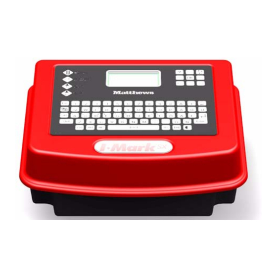
O V E R V I E W The Control Unit Main parts. See also “Connecting External Equipment” on page 16. Front view Side view Power on/off Keyboard with display Rear view RS-232 communication port Print head connector A Print head connector B The standard Matthews warranty is void if any other than Matthews cables are... -
Page 12: Dimensions
O V E R V I E W Dimensions Weight: 2,5 kg (5,5 lb.) Space for cables I•Mark SX-32e Technical Manual Version: 8 Issue: 1... -
Page 13: Installation
INSTALLATION For information on basic Please follow these instructions in the order they appear in the Installation chapter. procedures such as navigating the menu The correct sequence of events is: structure and getting Set up each system component mechanically but do not connect to the control help, please see the “Getting Started”... -
Page 14: Print Heads
I N S TA L L A T I O N Lethal voltages are present in this equipment when electrical power is applied. For personal safety and to prevent damage, it is essential that the control unit is positioned so that it does not come into contact with liquids, e.g. - Page 15 I N S TA L L A T I O N What is a Printout Activator? A printout activator, or trigger, sends a signal to the control unit when it has detected the presence of a print target. This informs the control unit when to start a print cycle. Each time the control unit receives the signal it will start a print cycle.
-
Page 16: Speed Encoder
I N S TA L L A T I O N Speed Encoder For connecting a speed encoder to the control unit, see “Connecting a Printout Activator and Speed Encoder” on page 18. Note that the standard Matthews warranty is void if any other than a Matthews approved speed encoder is connected to this control unit. -
Page 17: Rs-232 Communication Device
I N S TA L L A T I O N Installing Only use Matthews approved speed encoders. A speed encoder is a precision instrument and should be mounted accordingly. Place the speed encoder so that it is well protected from knocks and vibration. Ensure that there is no play between the speed encoder shaft and the drive as this will otherwise affect the printout. -
Page 18: Connecting External Equipment
I N S TA L L A T I O N Connecting External Equipment This chapter assumes that: • the system components are in place, see “Positioning and Mounting” on page 11. The next step is to connect the external equipment to the control unit. The following equipment can be connected: Rear view RS-232 communication port... - Page 19 I N S TA L L A T I O N Connecting Print Heads Damage or incorrect operation will occur if print heads from different ranges are used together on the same control unit. Always switch the control unit off before connecting or disconnecting cables. 7 valve heads 1x16...
- Page 20 I N S TA L L A T I O N Connecting a Printout Activator and Speed Encoder Always switch the control unit off before connecting or disconnecting cables. Rear view Speed encoder* Printout activator** * Also alternative connector for printout activator. ** Preferred connector for printout activator.
- Page 21 I N S TA L L A T I O N Connecting an RS-232 Communication Device Always switch the control unit off before connecting or disconnecting cables. Rear view RS-232 communication device Print Relay Signal Always switch the control unit off before connecting or disconnecting cables The SX-32e has a print relay function, which can be utilised to signal when the print head is active.
-
Page 22: Setting Up The Control Unit
I N S TA L L A T I O N Setting Up the Control Unit This chapter assumes that: • the system components are in place, see “Positioning and Mounting” on page 11. • external equipment has been connected to the control unit, see “Connecting External Equipment”... -
Page 23: National Settings
I N S TA L L A T I O N National Settings Setting the Display Language, Measurement Units, and Zero format. This option is used to set the display language and units of measure (Metric or Imperial). In addition the format for zeros can also be set, either with or without an oblique strike, as shown above. - Page 24 I N S TA L L A T I O N Margin settings • Margin for each print head Print head settings • Print head type • Print head configuration • Standby compensation Printer Settings Current printer settings screen Printout height Column spacing Print head number: print direction Dot size...
- Page 25 I N S TA L L A T I O N Enter encoder factor setting - For all print heads Speed encoder Description For setting the number of speed encoder pulses per distance unit (metres or feet) when a speed encoder is used. The encoder factor setting can be calculated as follows: ×...
- Page 26 I N S TA L L A T I O N If the pulses per shaft revolution value is given in the wrong units system (metric or imperial), change the SX-32e to reflect the encoder’s units (see “National Settings” on page 21) and then enter the encoder factor setting.
- Page 27 I N S TA L L A T I O N Enter dot size setting - For all print heads Description For setting the size of all printed dots. Comments • A high value gives a large dot size. • See the documentation received with the print head for a recom- mended value.
- Page 28 I N S TA L L A T I O N Select terminate print setting - For all print heads Description For stopping printout at the end of the print target. See also mark length. Comments Printout is terminated at end of Printout continues regardless of the the print target.
- Page 29 I N S TA L L A T I O N Select update mode - For all print heads Description This setting is used to set the method by which objects in a message, such as counters, are updated. Comments •...
- Page 30 I N S TA L L A T I O N Enter multiple mark setting - For all print heads Description For setting how many times a message is printed each time a printout is activated. Comments • 0 = Print continuously until the printout activation signal ends. •...
- Page 31 I N S TA L L A T I O N Enter mark length setting - For all print heads This parameter only appears if multiple mark is set for continuous or multiple printing (zero or more than 1). Description For setting the distance from the start of one printout to the start of the next during continuous or multiple printing.
- Page 32 I N S TA L L A T I O N Margin Settings Current margin settings screen Margin setting for each print head (A) Example A - Margin B - Printout activated here C - Print target travel direction Margin settings apply to all messages. Margin settings are set for each print head in turn.
- Page 33 I N S TA L L A T I O N Enter margin setting - For each separate print head Description For setting the distance between the point of printout activation (by the leading edge of the print target) and print start, for each print head. Comments •...
- Page 34 I N S TA L L A T I O N Select print head configuration setting - For all print heads Description For setting the type of print head, number of print heads to be used and how many valves each head has. Comments •...
- Page 35 I N S TA L L A T I O N Print Relay Signal Current relay settings screen For setting the relay output to either off or to print status. When set to print status a signal is sent through the 15 pin I/O encoder port, whenever the print head is active. Refer to “Print Relay Signal”...
- Page 36 I N S TA L L A T I O N • Week names (max 2 characters) • Month names (max 16 characters) • Year names (max 4 characters, 10 possible entries) The above values are initially set by default, having the following formats: •...
-
Page 37: Checking And Finalizing The Installation
I N S TA L L A T I O N Checking and Finalizing the Installation This chapter assumes that: • the system components are in place, see “Positioning and Mounting” on page 11. • external equipment has been connected to the control unit, see “Connecting External Equipment”... -
Page 38: Checking Print Head Operation
I N S TA L L A T I O N Deactivate the printout trigger by, for example, removing the object from in front of the photocell. The Trigger active box should now become empty ( ) indicating that the signal from the trigger is no longer being received. -
Page 39: User Level Security
I N S TA L L A T I O N • [Blank] - An empty message used for ensuring that the print heads, which are not being tested, do not print. This message can not be edited or deleted. Switch the control unit on. - Page 40 I N S TA L L A T I O N Basic user level - Unrestricted access to tools for: • selecting messages for printout. • flushing the print heads. Full access - No password required Temporary access - Password class 1 or 2 required Temporary access - Password class 2 required Advanced user level - Unrestricted access to tools for: •...
- Page 41 I N S TA L L A T I O N Select a user level and press OK. Enter the class 2 password (“+4631”) and press OK. The selected user level is now set. Repeat the above to change the user level security setting.
- Page 42 I N S TA L L A T I O N I•Mark SX-32e Technical Manual Version: 8 Issue: 1...
-
Page 43: Appendices
APPENDICES The Mounting Bracket Using the mounting bracket kit, the SX-32e can be fixed into position either verti- cally or horizontally. In both cases the lower section can be rotated 180 degrees so that the cable connections can be accessed from the front or rear (above or below when vertical). -
Page 44: Switching On For The First Time
A P P E N D I C E S Mounting the Bracket 1 Using the four screws supplied, attach the wall bracket to the rear of the SX-32e. Make sure that the screws are not over tightened as this may damage the threads. The bracket can be mounted so that the cable connections are above or below (in front or behind) the SX-32e. -
Page 45: Restoring Factory Settings
A P P E N D I C E S 2 Select the desired display language and press OK. The supported languages include: English English Italiano Italian Svenska Swedish Nederlands Netherlands Deutsch German Cesky Czech Republic Français French Polski Polish Español Spanish Türkçe... -
Page 46: Tips For Barcode Printing
A P P E N D I C E S Factory Settings The following table shows the factory setting for each parameter. Group name Parameter Default setting New message Font Bold Reversed Normal Inverted Normal Negative Normal Configuration - Printer settings Direction Left Speed source... -
Page 47: Troubleshooting Problems
A P P E N D I C E S Troubleshooting Problems See also the documentation received with your print head or ink supply unit. Check all cable connections before carrying out the following. Contact a qualified service technician if the following does not help. General Printout Problems This table shows the faults which are detected at the print target after printout. - Page 48 A P P E N D I C E S Problem Possible Cause Remedy Printout clipped (truncated) Mark length setting too low. See “Mark Settings” on page 27. One or more print head Clean head’s front panel. nozzles blocked. Flush head. With software version 1.3 and above there is a special flush function: Pressing...
-
Page 49: Technical Specifications
A P P E N D I C E S Technical Specifications Dimensions (WxLxH) 286 mm x 251 mm x 126 mm (11,2 in. x 9,9 in. x 5,0 in.) Weight 2,5 kg (5,5 lbs.) Power supply 100-240 V AC nominal, 50-60 Hz, auto adjusting (85-264 V AC maximum range) Ambient conditions Humidity 10-95%, non-condensing - Temperature 0-45ºC... -
Page 50: Documentation History
A P P E N D I C E S Documentation History Each Technical Manual has been written for a specific control unit software version or major hardware feature. The following table shows which manual should be used with which control unit. Note that in no way does this table show compatibility between software versions. -
Page 51: Setup Log
A P P E N D I C E S Setup Log Use these pages to record how your SX-32e has been set up. This information could be useful if the printer memory becomes damaged or if another printer shall be set up in the same way. - Page 52 A P P E N D I C E S Group name Parameter Current setting Communication Baud rate ..............Parity ..............Flow control ..............Miscellaneous Flush fluid ..............(Sheet 2 of 2) Messages List the messages stored in memory Message name Description/settings Message Objects List the message objects stored in memory...
- Page 53 A P P E N D I C E S Backup of Printer Enter the date and location of stored file Enter how to contact file owner I•Mark SX-32e Technical Manual Version: 8 Issue: 1...
- Page 54 A P P E N D I C E S I•Mark SX-32e Technical Manual Version: 8 Issue: 1...
-
Page 55: Index
Index Numerics Interface 32 Keyboard 9 20mA current loop 15 Date and time 33 Calender Name 33 Default 43 Default settings See Factory settings Labelling 5 Advanced user level 37 Default user level 38 Language in display 42 Automatic speed setting Delay Length of printout 29 See Speed encoder... - Page 56 INDEX Total printouts counter 36 Trigger 25 Padlock symbol 37 Real time clock Skipping 26 Parity 32 See Date and time Source 25 Password protection 37 Relay Update mode 27 Photocell 35 See print relay signal Troubleshooting 35 See Printout activator Repeat print Truncated printout 29 Print activator 8...
- Page 57 INDEX I•Mark SX-32e Technical Manual Version: 8 Issue: 1...
Need help?
Do you have a question about the I-Mark SX-32e and is the answer not in the manual?
Questions and answers
Entering the message,saved and not activating the printer