Siemens SIMATIC TI505 Installation And Operation Manual
S5 unlink adapter
Hide thumbs
Also See for SIMATIC TI505:
- User manual (127 pages) ,
- User manual (91 pages) ,
- User manual (28 pages)
Table of Contents
Advertisement
Quick Links
Download this manual
See also:
User Manual
Advertisement
Table of Contents

Related Manuals for Siemens SIMATIC TI505


Summary of Contents for Siemens SIMATIC TI505
- Page 1 SIMATIC TI505 S5 UNILINK Adapter Installation and Operation User Manual Order Number: PPX:TIWAY-8126-2 Manual Assembly Number: 2587871-0065 Second Edition...
- Page 2 Technical data is subject to change. contents is not permitted without express consent of Siemens Industrial Automation, Inc. All rights, including rights We check the contents of every manual for accuracy at the created by patent grant or registration of a utility model or time it is approved for printing;...
- Page 3 MANUAL PUBLICATION HISTORY SIMATIC TI505 – S5 UniLink Adapter Installation and Operation Order Manual Number: PPX:505–8116–2 Refer to this history in all correspondence and/or discussion about this manual. Event Date Description Original Issue 09/92 Original Issue (2800120–0001) Second Issue 04/94...
- Page 4 LIST OF EFFECTIVE PAGES Pages Description Pages Description Cover/Copyright Second History/Effective Pages Second iii — x Second 1-1 — 1-5 Second 2-1 — 2-8 Second 3-1 — 3-12 Second A-1 — A-11 Second B-1 — B-9 Second C-1 — C-3 Second Index-1 —...
-
Page 5: Table Of Contents
Contents Preface Chapter 1 Product Overview Description of the S5 UniLink Adapter ..........Connecting a SIMATIC S5 Controller to a TIWAY Network . - Page 6 Modem Interface Ports ............RS-232-C Modem Interface Ports .
- Page 7 Input Bytes — CP 525 ‘E’ Type ........... . Description .
- Page 8 Appendix C S5 Adapter/CP 525 Error Codes S5 UniLink Adapter Primitive Exceptions ......... . Primitive Exceptions .
- Page 9 List of Figures S5 UniLink Adapter Interface ........... . S5 UniLink Adapter .
- Page 10 List of Tables S5 UniLink Adapter Models ............S5 UniLink Adapter Models .
- Page 11 Preface Purpose of this This manual is intended to help you accomplish the tasks required to install Manual and operate the S5 UniLink Adapter with the SIMATIC S5 Personality Interface Module (PIM). This manual assumes that you are already familiar with the contents of the ...
- Page 12 240 VAC Technical If you have any questions about this product or need technical assistance, Assistance contact your Siemens Industrial Automation, Inc. distributor. If you need assistance in contacting your U.S. distributor, call 1-800–964-4114. Preface S5 UniLink Adapter Installation and Operation...
- Page 13 Chapter 1 Product Overview Description of the S5 UniLink Adapter ..........Connecting a SIMATIC S5 Controller to a TIWAY Network .
-
Page 14: S5 Unilink Adapter Components
Description of the S5 UniLink Adapter Connecting a The S5 UniLink Adapter allows you to connect an S5 Programmable SIMATIC S5 Controller to a TIWAY I network, as shown in Figure 1-1. The S5 Adapter Controller to a provides the hardware and software that customizes the interface to an S5 TIWAY Network PLC through a SIMATIC CP 525 Communications Processor. -
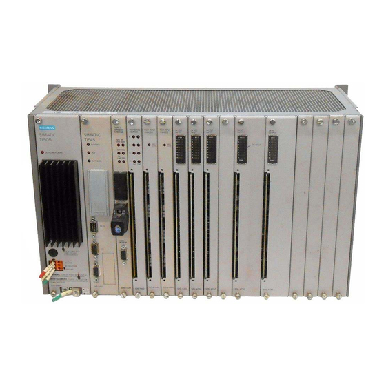
Page 15: S5 Unilink Adapter
UniLink Adapter S5 PIM A000653 Figure 1-2 S5 UniLink Adapter S5 PIM (shown installed in UniLink Adapter) A000653a Figure 1-3 S5 Personality Interface Module (PIM) S5 UniLink Adapter Installation and Operation Product Overview... -
Page 16: Adding The S5 Unilink Adapter To The Tiway Network
TIWAY I System Characteristics TIWAY Network TIWAY I is a bus structure Local Area Network (LAN) designed for industrial environments. The TIWAY I network connects a series of PLCs and other devices to one or more host computers. ... -
Page 17: Primitive Command Set
Primitive Primitives are high level commands used by the TIWAY I network to access Command Set data types in different secondary devices. The TIWAY I network primitives supported by the S5 UniLink Adapter are a subset of the entire TIWAY primitive command set, as represented in Figure 1-5. -
Page 18: Overview
Chapter 2 Installation and Set-up Overview ............... The S5 UniLink Adapter as a TIWAY Secondary . -
Page 19: Main Steps For Setting Up The S5 Unilink Adapter
Overview The S5 UniLink This chapter provides an introduction to the operation and set-up of the Adapter as a TIWAY S5 UniLink Adapter. Secondary During normal operation, requests are sent over the TIWAY network to the S5 UniLink Adapter; thus it functions in the same manner as any other secondary in the network. - Page 20 Programming the For the S5 UniLink Adapter to establish communications with the CP 525 CP 525 module, the following prerequisites must be met. Use the PG programmer to load these parameters. • The STEP 5 user program in the CPU must include the data handling blocks SEND ALL RECEIVE ALL...
-
Page 21: S5 Unilink Adapter Interface
Cabling the Components S5 Interface The S5 UniLink Adapter communicates with a CP 525 Communications Overview Processor module located in an S5 PLC through a serial binary data interface using EIA RS-232-C control, data, and timing signals. Basic Cable Connect the S5 PLC and the S5 UniLink Adapter as shown in Figure 2-2. Connections TIWAY I SIMATIC S5 PLC... - Page 22 S5 Interface Pin The pin assignments for the S5 interface are shown in Figure 2-3. Any pins Assignments not listed in the diagram should remain unused in order to prevent damage to the communications processor or the S5 UniLink Adapter. NOTE: Do not exceed 50 feet in length for the communications cable.
-
Page 23: S5 Unilink Adapter Dipswitch Location
Setting the Dipswitches Dipswitch Location Two banks of dipswitches are provided on the S5 UniLink CPU board, accessible by opening the cover plate on the face of the unit (see Figure 2-4). S5 PIM Dipswitch 1 Dipswitch 2 A000653a I003643 Figure 2-4 S5 UniLink Adapter Dipswitch Location Dipswitch 1 Dipswitch 1 is used to configure the S5 Interface Port and the TIWAY... -
Page 24: S5 Unilink Dipswitch 1 Settings
Figure 2-5 shows the settings for Dipswitch 1. Dipswitch 1 Network Parameters Up = 1 Down = 0 TIWAY Network NRZI = Up 0 0 – CPU 1 Data Rate Settings NRZ = Down 0 1 – CPU 2 Switches 1 0 –... -
Page 25: Installing The S5 Personality Interface Module
Installing the S5 Personality Interface Module Installing the PIM The S5 Personality Interface Module contains the software required to establish an interface with the S5 series of PLCs. Although the faceplate of the S5 UniLink Adapter contains an opening that shows the label on the S5 PIM, it is not large enough to allow you to insert or remove the PIM while the faceplate is closed. - Page 26 Chapter 3 TIWAY I Network Communication Local Line Interface Ports ............Overview .
-
Page 27: Local Line Interface Ports
Local Line Interface Ports Overview The S5 UniLink Adapter is available in four models, offering a choice of two physical interfaces for network communications: Local Line or RS-232-C interfaces, in different voltage versions. Table 3-1 lists the model numbers, the type of interface, and the supply voltage for each model. Table 3-1 S5 UniLink Adapter Models Model Number Network Port... -
Page 28: Tiway I Bus Structure
Local Line Pin The pin assignments for these ports are listed in Table 3-2. Assignments Table 3-2 Local Line Connector Pin Assignments Name Description Reserved Reserved Shield Cable shield and signal common Reserved Reserved LLM+ Positive biased signal line Reserved Reserved LLM–... -
Page 29: Chapter 3 Tiway I Network Communication
Local Line Interface Ports (continued) Figure 3-3 is a chart showing the maximum cable distances compared to the number of stations on the TIWAY I network. 19.2 k bps 38.4 k bps Belden 9860 57.6 k bps 115.2 k bps 115.2 k bps or lower Belden 9271 Cable Unit Loading (Number of Stations) -
Page 30: Modem Interface Ports
Modem Interface Ports RS-232-C Modem The modem interface is a standard Type E DTE configuration as defined in Interface Ports the EIA RS-232-C standard that uses EIA RS-423 drivers. This interface uses a female 25-pin D-type connector on both Ports 1 and 2 as shown in Figure 3-4. -
Page 31: Modem Specifications
Modem Interface Ports (continued) The line drivers and receivers meet the requirements for the RS-423 and RS-232-C standards. The modem interface is user-selected for either asynchronous or synchronous operation at data rates of 110, 150, 300, 600, 1200, 2400, 4800, 9600, 19.2K, 38.4K, 57.6K, and 115.2K bits per second. Modem For communication applications longer than the 25,000 feet limit of the Specifications... -
Page 32: Redundant Media Transmission
Redundant Media Transmission Alternate Channel Most TIWAY I conformant devices support a redundant media scheme Port which provides active access to a device over one of two independent media channels. Port 2 on both Local Line and RS-232 models of the S5 UniLink Adapter provides support for redundant media transmission. -
Page 33: Tiway I Hdlc Network Protocol
TIWAY I HDLC Network Protocol The TIWAY I network uses the HDLC protocol in the unbalanced, normal response mode (UNRM) for transmission of commands and responses. In this mode, a single Network Manager (primary) controls the flow of messages between secondary devices. Information flows between the primary and secondaries inside HDLC I-Frames or information frames. -
Page 34: S5 Interface Port Communications
S5 Interface Port Communications Overview In automation engineering, data must often be exchanged between programmable controllers or between a programmable controller and a central process computer. The data exchange can be implemented using the communications processor CP 525 with its interpreter RK 512 and the procedure 3964R. -
Page 35: Transmitting With The 3964R Procedure
Transmitting with the 3964R Procedure NOTE: The term procedure refers to the device initiating the transfer, and the term partner refers to the receiving device. Link Establishment To establish the link, the procedure sends the control character STX. If the partner replies within the time allowed of 2000 ms, the procedure starts the transmission. -
Page 36: Receiving With The 3964R Procedure
Receiving with the 3964R Procedure Link Establishment After a successful transmission of the data information has been made to the partner, the procedure enters the idle state awaiting the link to be established by the partner. If the procedure receives any character (except STX) while in the idle state, it waits until the character delay time (220 ms) has elapsed and then sends a NAK character. -
Page 37: Longitudinal Parity (Bcc Comparison)
Receiving with the 3964R Procedure (continued) Longitudinal Parity The BCC error check byte is calculated by an exclusive-OR of all data bytes (BCC Comparison) contained in the message. The terminating characters DLE and ETX are also included in the BCC calculation. For Additional For more detailed information concerning the RK 512 protocol and 3964R Information... -
Page 38: Memory Type Overview
Appendix A SIMATIC S5 Memory Mapping Memory Type Overview ............Overview . -
Page 39: Overview
Memory Type Overview Overview This appendix describes how the TI505 data types map to S5 data types and vice versa. Each of the eleven S5 data types supported by the CP 525 module is described in detail as seen through the CP module in relation to each one’s TI500/TI505 counterpart. -
Page 40: Floating-Point Conversion
Floating-Point Conversion Description The TI500/TI505 floating-point representation is different from the S5 representation; therefore, the S5 PIM will have to perform a conversion. The sign bit of the TI500/TI505 floating-point is the same as the sign bit of the S5 mantissa. You can determine how the exponent and mantissa values are derived from the equations below. -
Page 41: Data Block - Cp 525 'D' Type
Data Block — CP 525 ‘D’ Type Description The S5 Data Block memory as accessed through the CP 525 module refers to memory that is organized by 256 blocks of 256 words (16 bits) for a total of 64K words of memory. Because the Data Block memory is user-configurable in the CPU, the S5 PIM assumes no knowledge of the accessible memory ranges for each block. -
Page 42: Extended Data Block - Cp 525 'X' Type
Extended Data Block — CP 525 ‘X’ Type Description The S5 Extended Data Block memory, as accessed through a CP module, refers to memory that is organized by 256 blocks of 256 words (16 bits) for a total of 64K words of memory. Because the extended data block memory is user configurable in the CPU, the S5 PIM assumes no knowledge of the accessible memory ranges for each block. -
Page 43: Input Bytes - Cp 525 'E' Type
Input Bytes — CP 525 ‘E’ Type Description The S5 Input Bytes memory, as accessed through a CP module, refers to memory that is organized in 128 contiguous bytes of memory. Because the process input image memory area (E memory) is accessible only if a corresponding I/O module is in use, the S5 PIM assumes no knowledge of the accessible memory area of the process input image. -
Page 44: Output Bytes - Cp 525 'A' Type
Output Bytes — CP 525 ‘A’ Type Description The S5 Output Bytes memory, as accessed through a CP module, refers to memory that is organized in 128 contiguous bytes of memory. Because the output image memory area (A memory) is accessible only if a corresponding I/O module is in use, the S5 PIM assumes no knowledge of the accessible memory area of the process output image. -
Page 45: Flag Bytes - Cp 525 'M' Type
Flag Bytes — CP 525 ‘M’ Type Description The S5 Flag Bytes memory, as accessed through a CP module, refers to memory that is organized by 255 contiguous bytes of memory. The TT types that map to this type of S5 memory are Packed Control Register (TT Type 08) and Unpacked Control Register (TT Type 05). -
Page 46: Timer - Cp 525 'T' Type
Timer — CP 525 ‘T’ Type Description The S5 Timer memory, as accessed through a CP module, refers to memory that is organized by 256 contiguous words of memory. Because the accessible timer memory is different for different CPUs, the S5 PIM assumes no knowledge of the accessible memory ranges for timer memory. -
Page 47: Counter - Cp 525 'Z' Type
Counter — CP 525 ‘Z’ Type Description The S5 Counter memory, as accessed through a CP module, refers to memory that is organized by 256 contiguous words of memory. Because the accessible Counter memory is different for different CPUs, the S5 PIM assumes no knowledge of the accessible memory ranges for Counter memory. -
Page 48: S5 Data Types Not Supported By S5 Pim
A.10 S5 Data Types Not Supported by S5 PIM Due to significant differences in the internal memory structure and architecture between the TI500/TI505 PLCs and the S5 PLCs, no compatible memory translations to these specific S5 data types are available. Analog I/O Bytes: The S5 Analog I/O Bytes memory type as accessed through a CP module is CP 525 ‘P’... - Page 49 Appendix B TIWAY I Primitives Supported by S5 PIM Overview ............... Exception .
-
Page 50: Overview
Overview TIWAY I Primitives provide a uniform command level access to industrial devices through the TIWAY I Industrial Local Area Network. This section describes the set of primitives supported by the S5 UniLink Adapter*. Exception The S5 PIM supports the following exception field values. Request: None Response: LLLL 00 PP DDDD... -
Page 51: Native
NOTE: The S5 PIM checks all requests based on the maximum memory ranges allowed by the CP module and assumes no knowledge of the actual memory ranges in the CPU. Thus if a request is inside the range of the CP module but outside the range of the CPU, the exception returned is 80DD. -
Page 52: Status
Status Primitive 02 is the Machine Status primitive. It reports the current operational state of the attached device in common format for all types of attached devices. Listed below are the response field values supported by the S5 PIM. Request: LLLL 02 Response: LLLL 02 HH EE FF GG Symbol... -
Page 53: Primitive Format Configuration
Primitive Format Primitive 04 is the format primitive that allows you to determine the Configuration maximum length of the primitive acceptable to the Network Interface Module. The buffer length is returned in number of bytes. Request: LLLL 04 Response: LLLL 04 NNNN MM EE FF GG BB ... BB Symbol Value Definition... -
Page 54: Read Random Block
Read Random Primitive 21 is a command to read several random blocks of contiguous Block memory. Request: LLLL 21 TT NNNN AAAA (repeated) Symbol Definition Data element type. NNNN Number of locations. AAAA Data element location. Response: LLLL 21 HH XX BB DD ... DD Symbol Definition Operational status (see Status). -
Page 55: Write Random Block
Write Random This primitive replaces the specified blocks of data element locations with Block the data included in the request. Request: LLLL 31 TT NNNN AAAA DD ... DD (repeated) Symbol Definition Data element type. NNNN Number of locations. AAAA Data element location. -
Page 56: Gather Block
Gather Block The Gather Block primitive specifies which blocks (as defined by the Define Block primitive) will be read. The blocks are specified through a 32-bit mask (EEEEEEEE). Each bit position in the bit mask corresponds to a block that was defined with primitive 50, Define Block. -
Page 57: Write And Gather Block
Write and Gather The Write and Gather Block primitive specifies which blocks (as defined Block with Define Block primitive 50) will be read. It also allows a user to replace any contiguous data element locations. The blocks are specified through a 32-bit mask (EEEEEEEE). - Page 58 Appendix C S5 Adapter/CP 525 Error Codes S5 UniLink Adapter Primitive Exceptions ......... . Primitive Exceptions .
-
Page 59: Appendix C S5 Adapter/Cp 525 Error Codes
S5 UniLink Adapter Primitive Exceptions During operation, two possible error codes could be returned by the S5 UniLink Adapter: primitive exceptions, and CP 525 errors. Primitive The error byte of a primitive exception contains one of the following. Exceptions Request: None Response: LLLL 00 PP DDDD Table C-1 Primitive Exception Error Byte... -
Page 60: Cp 525 Error Codes
CP 525 Error Codes Description of If the CP 525 module responds with an error code, it is returned in the CP 525 Error Codes following 80DD word. The DD field will contain the CP 525 error code byte. In order to determine the meaning of this error code, you must refer the value DD to the appropriate CP 525 manual. - Page 61 Index Adapter Error codes components, 1-2 CP 525, C-3 installing, 2-2–2-8 UniLink, C-2 Cable connections Floating-point CP 525 interface port, 2-4 conversion, A-3 maximum cable length, 2-5 S5 value, A-3 pin assignments, 2-5 TI500/TI505 value, A-3 S5 UniLink Adapter port, 2-4 Communications local line, 3-2–3-4 receiving, 3964R procedure, 3-11...
- Page 62 Primitive commands configuration, B-4 define block, B-7 Manuals, ix exception, B-2 Memory gather block, B-8 quick reference chart, A-2 native, B-3 types, A-2 primitive format configuration, B-5 read block, B-5 Memory types read random block, B-6 See also CP 525 memory types status, B-4 absolute address, A-11 write and gather block, B-9...
- Page 63 protocol, 3-8 Technical assistance, x TIWAY I network UniLink models, x, 3-2 connecting S5 PLCs, 1-4 local area network, 1-4 Network Interface Modules, 1-4 parameters, 2-7 port, 2-6 Voltage supply, x, 3-2 Index-3...
- Page 64 Customer Registration We would like to know what you think about our user manuals so that we can serve you better. How would you rate the quality of our manuals? Excellent Good Fair Poor Accuracy Organization Clarity Completeness Overall design Size Index Would you be interested in giving us more detailed comments about our manuals?
- Page 65 IN THE UNITED STATES BUSINESS REPLY MAIL PERMIT NO.3 FIRST CLASS JOHNSON CITY, TN POSTAGE WILL BE PAID BY ADDRESSEE SIEMENS INDUSTRIAL AUTOMATION, INC. 3000 BILL GARLAND RD. P.O. BOX 1255 JOHNSON CITY TN 37605–1255 ATTN: Technical Communications M/S 3519 FOLD...
- Page 66 SIMATIC is a trademark of Siemens AG. TIWAY I, 5TI, PM550 and UniLink are trademarks of Siemens Industrial Automation, Inc. Smartmodem is a trademark of Hayes Microcomputer Products, Inc. TI500. TI505, TI545, and TI565 are trademarks of Texas Instruments Incorporated.