
Related Manuals for MSA Chillgard 5000


Summary of Contents for MSA Chillgard 5000
- Page 1 Operating Manual Chillgard 5000 Refrigerant Monitor Order No.: 10178535/00 MSAsafety.com...
- Page 2 The warranties made by MSA with respect to the product are voided if the product is not installed and used in accordance with the instructions in this manual. Please protect yourself and your employees by following the instructions.
-
Page 3: Table Of Contents
Contents MSA Permanent Instrument Warranty ........... - Page 4 Gas Reading Accuracy ............. 70 Chillgard 5000...
- Page 5 Chillgard 5000 - Modbus RTU (Holding Registers) ........
-
Page 6: Msa Permanent Instrument Warranty
(1) year, such as, but not limited to, nonrechargeable batteries, filament units, filter, lamps, fuses, etc. MSA shall be released from all obligations under this warranty in the event that repairs or modifications are made by persons other than its own or authorized service personnel or if the warranty claim results from physical abuse or misuse of the product. -
Page 7: Warnings And Cautions
Warnings and Cautions Warnings and Cautions The Chillgard 5000, hereafter also referred to as "the device", is a gas monitor intended for indoor use in mechanical equipment rooms or commercial spaces where refrigerant equipment, such as centrif- ugal chillers, is used. The device is specified to support compliance with federal, state, and local safety codes that govern emissions. - Page 8 Clearly mark the circuit breaker as the discon- necting unit for the device. Properly vent the exhaust of the Chillgard 5000 system to a safe area. Improper venting of the exhaust can cause serious personal injury or death. Refer to Section 4.4.5, "Exhaust Venting".
-
Page 9: Description
Description Description The Chillgard 5000 provides continuous monitoring of refrigerant gas levels for up to 16 points in nonhazardous areas. With the ability to read down to 1 ppm, the device provides a response to a refrigerant leak, supporting the safety of personnel and the environment, and equipment efficiency. -
Page 10: Identifying Your Unit
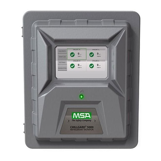
Description Identifying Your Unit Fig. 1 Front of device 7″ resistive touchscreen user interface Power indicator NOTE: Optional strobe not shown. Fig. 2 Back of device Mounting locations (10″ x 14 5/8″) Chillgard 5000... - Page 11 Description Fig. 3 Right side of device AC power wiring cutout Protective earth grounding cutout (optional) Relay wiring cutout Approval and unit identification label Fig. 4 Left side of device Latches (lockable with padlock) Signal wiring cutouts Chillgard 5000...
- Page 12 Description Fig. 5 Bottom of device Sample line identification labels Internal alarm sounder Calibration port IP rated vent Exhaust port (do not block) Fig. 6 Internal touchpoints Fuses AC wiring cover Internal filters ESD tie-off location Chillgard 5000...
-
Page 13: Visible Alarming Devices
2500 ft (762 m). For a list of approved parts and how to order them, refer to Section 13, "Ordering Information". For installation instructions, refer to Section 15, "Appendix B: Installation of Optional Equipment". Chillgard 5000... -
Page 14: Communications
Full scale is 1000 ppm. Normal gas readings are at 4–20 mA. The reading is proportional to the detected gas concentration. For the factory default of 100% full scale setting (0.016 mA = 1 ppm): Output Gas Concentration (mA) (ppm) 1000 Chillgard 5000... - Page 15 21 mA 0–10 Vdc The voltage output can be used to identify any active gas sample line. Sample Line 4 or 8 pt system 16 pt system While the device is in calibration mode, the output is 10 Vdc. Chillgard 5000...
-
Page 16: Installation
Remote horn (if equipped) e) Protective foam Notify MSA of any shortages immediately. Keep the original packaging in case it is necessary to return the device for service. Release the two latches on the left side of the device. -
Page 17: Mounting Guidelines
Use all four mounting holes provided on the device (Fig. 9). • Away from exposure to direct solar heating and other excessive heat sources. • Away from wet or damp conditions. • Away from areas that are dirty or exposed to oils or chemicals. Fig. 7 Mounting location Chillgard 5000... -
Page 18: Sample And Exhaust Lines
6 mm OD x 4 mm ID Polyurethane tubing (ether based) 6 mm OD Copper tubing 6 mm OD Stainless steel tubing NOTICE Use the appropriate tools to give a clean, smooth end to the tubing when it is cut. Chillgard 5000... -
Page 19: Routing And Placement
Do a smoke test of the mechanical room to determine the flow pattern and allow for optimal placement of the sample lines. Ventilation smoke tubes for this use are available from MSA (P/N 458480). For a list of approved parts and how to order them, refer to Section 13, "Ordering Information". -
Page 20: End-Of-Line Filters
Failure to follow these warnings can result in serious bodily injury or death. Install an end-of-line filter (MSA P/N 711561) in each sample line to decrease contaminants in the sample lines and device. Do the following procedure to install end-of-line filters: Remove the new end-of-line filter from the bag. -
Page 21: Exhaust Venting
To achieve this connection, install a 10 AWG or larger copper wire between the grounding lug terminal strip on the right side of the Chillgard 5000 device and the grounding point (protective earth). The wire length cannot be longer than 6 ft (2 m). - Page 22 Installation Fig. 11 Chillgard Wiring Diagram Chillgard 5000...
-
Page 23: Electrical Power Supply Requirements
Remove the circuit board cover. Remove the ac power wiring hole plug. (10) Install conduit hubs that are suitable for fiberglass enclosures through the ac power wiring hole plug openings. (11) Put the ac power wiring through the conduit. Chillgard 5000... -
Page 24: Relay Outputs
Refer to the Chillgard Wiring Diagram (Fig. 11) for details. The Chillgard 5000 has the following five single-pole, double-throw (SPDT) relays. The relay contacts are rated 8 A at 240 Vac/24 Vdc. Each relay can be connected as normally open (NO) or normally closed (NC). -
Page 25: Initial Setup
"Next". When a language is selected, the change is instantaneous. On the "Date & Time Setup" screen, select the "Date" tab. The date format can be MM/DD/YYYY or DD/MM/YYYY depending on the language setting. Chillgard 5000... - Page 26 If applicable, select "AM" or "PM". Select "Next". NOTE: A valid entry for the time is necessary to continue. If this error pop-up shows, select "OK" to return to the previous screen and supply a value. Chillgard 5000...
- Page 27 (11) The "Initial Setup" screen shows a check mark beside the "Language/Date & Time/Password" step to indi- cate that it is complete. Select "Continue" to go to the point configuration setup. Chillgard 5000...
-
Page 28: Point Configuration
On the "Point Configuration" screen, select "Next". The "Initial Setup" screen shows a check mark beside the "Point Configuration" step to indicate that it is complete. Select "Continue" to go to the gas configu- ration setup. Chillgard 5000... -
Page 29: Gas Configuration
Alarm, as applicable. NOTE: If the "Setpoints" tab is selected but a gas has not been selected, the options on the "Configure Gas" screen will be inactive. The options for the configuration settings for cautions, warnings, and alarms are identical. Chillgard 5000... - Page 30 NOTE: If the "Points" tab is selected but a gas has not been selected, the options on the "Configure Gas" screen will be inactive. Only one gas can be assigned to a single point. Points that have already been assigned a gas are not available for selection. Chillgard 5000...
-
Page 31: Relay Configuration
Each relay is mapped to a specific predetermined function; that is, fault, alarm, warning, caution, or horn. On the "Configure Relays" screen, select "Edit" for the function to configure. NOTE: The options for the configuration settings for alarms, warnings, cautions, and the horn are identical. Chillgard 5000... - Page 32 Select "OFF". Select "Save". The updated settings for the relays show on the "Configure Relays" screen. Repeat Steps (1) through (5) for each relay to be configured. When all relays have been configured, select "Next". Chillgard 5000...
-
Page 33: Communications Output
Select the "Device Address" field, and use the alphanumeric keypad pop-up to enter a value. Select to accept the value. c) Select a baud rate for the connection. d) Select the RS485 Termination check box. e) Select "Done". Chillgard 5000... - Page 34 For a list of default settings, refer to Section 16, "Appendix C: Default Settings". The "Initial Setup" screen shows that all initial setup steps are complete. Select "Finished" to confirm the configuration settings and move to the "Initial Calibra- tion" screen. Chillgard 5000...
-
Page 35: Calibration
Do NOT do calibration with a constant-flow calibration gas regulator. Use only a demand-flow type regulator (MSA P/N 710269). Failure to follow this warning can result in incorrect calibration, damage to internal components, and inaccurate gas readings. -
Page 36: Initial Setup
Failure to follow these warnings can result in serious bodily injury or death. 6.2.1 Starting Calibration To start the calibration process, on the dashboard, select "Calibrate". On the bottom of the device, remove the pin from the calibration port. Chillgard 5000... -
Page 37: Stopping Calibration
For zero-gas calibrations, disconnect the zero-gas scrubber tubing from the calibration port, then select "Next" on the device touchscreen. On the "Canceled" screen, select "Done". On the bottom of the device, install the pin in the cali- bration port. Chillgard 5000... -
Page 38: Zero Gas Calibration
"Done", and go to the next step. c) To return to the "Results" screen, select "Back". On the bottom of the device, install the pin in the cali- bration port. Remove the tubing from the calibration port. Chillgard 5000... -
Page 39: Span Gas Calibration
Disconnect the zero-gas scrubber tubing from the cali- bration port. On the device touchscreen, select "Next". Span Gas Calibration NOTE: To prevent zero-gas contamination, MSA recom- mends using different regulators to do zero gas calibration and span gas calibration. Close the cylinder valve. - Page 40 At the selected interval, a pop-up will signal the need for calibration. (15) Select "Next". (16) On the bottom of the device, install the pin in the cali- bration port. (17) Remove the tubing from the calibration port. Chillgard 5000...
-
Page 41: Unsuccessful Calibrations
If "Close" is selected, on the dashboard, a gray check mark indentifies the points that are affected by the unsuccessful calibration. The gas readings for these sample points are below the alarm threshold but may not be completely accu- rate. Chillgard 5000... -
Page 42: Routine Operation
To close the detail pop-up and return to the dashboard, select the X at the top right corner. To hold and lock onto a point for an extended period manu- ally, in the point detail pop-up, select "Hold". Chillgard 5000... -
Page 43: Point Hold
Predictive warnings indicate that it may be necessary to do troubleshooting or replace a part, not that there is a critical issue with the flow rate, sensor, or pump. Chillgard 5000... -
Page 44: Cautions, Warnings, And Alarms
Event Log, and a notification shows on the "Event Log" button on the dashboard. For information about the Event Log, refer to Section 7.7, "Event Log". A corresponding notification of the event shows on the "Diagnostics" screen. For information about diagnostics, refer to Section 8, "Diagnostics". Chillgard 5000... -
Page 45: Latching Events
The point tile on the dashboard shows in its normal state, and the event is considered resolved. A corresponding notification of the event shows on the "Diagnostics" screen. For information about diagnostics, refer to Section 8, "Diagnostics". Chillgard 5000... -
Page 46: Faults
To acknowledge the event and return to the dashboard, select "Acknowledge". If the fault can be related to a single or multiple points, the associated point tiles show on the dashboard with a yellow background. Chillgard 5000... -
Page 47: Critical Faults
All point tiles show on the dashboard with a yellow back- ground and a black X icon. NOTE: If more than four events occur, use the scroll bar to see the entire list of faults. To acknowledge the events collectively and return to the dashboard, select "Acknowledge". Chillgard 5000... -
Page 48: Event Log
In the Event Log, events are color coded by type: • Red = Caution, Warning, Alarm • Yellow = Fault, Unsuccessful Calibration • Green = Successful Calibration Select any event on the "All" tab to see a pop-up with the event details. Chillgard 5000... -
Page 49: Alarms
Use the scroll bar to move through the list of events. Select any event on the "Alarms" tab to see a pop-up with event details. Chillgard 5000... -
Page 50: Faults
Use the scroll bar to move through the list of events. Select any calibration event to see a pop-up with details. NOTE: The "As Found" value represents the performance reading before calibration is performed. The "As Left" value represents the performance reading after calibration is performed. Chillgard 5000... -
Page 51: Edit Settings
"Password Required" pop-up, enter the correct password. For help with forgotten passwords or password resets, contact local MSA Customer Service. 7.8.1 Preferences Use the "Preferences" option to change the settings for the language, date and time, password, and brightness of the device display. -
Page 52: Gas Configuration
To return to the "Gas" screen without saving the config- uration changes, select "Return without Saving". • To save the configuration changes and return to the "Configure Gas" screen, select "Save and Return". When the configuration changes have been saved, the "Settings" screen shows. Chillgard 5000... - Page 53 If an attempt is made to delete the only configured gas slot, a warning pop-up indicates that the action cannot be completed. Select "Cancel" to return to the "Configure Gas" screen. When the configuration changes have been saved, the "Settings" screen shows. Chillgard 5000...
-
Page 54: Point Configuration
To change the point name, select the name field, and use the alphanumeric keypad pop-up to assign a name with up to 18 characters. Select to accept the value. The entire 18 characters will only show on the "Point Detail" screen. Only 10 characters will show on the "Point Configuration" screen. Select "Save". Chillgard 5000... - Page 55 If an attempt is made to delete the only configured point, a warning pop-up indicates that the action cannot be completed. Select "Cancel" to return to the Point Configuration: Point #" screen. When the configuration changes have been saved, the "Settings" screen shows. Chillgard 5000...
-
Page 56: Relay Configuration
To return to the "Configure Relays" screen without saving the changes, select "Return without Saving". • To save the changes and return to the "Configure Relay" screen, select "Save and Return". When the configuration changes have been saved, the "Settings" screen shows. Chillgard 5000... -
Page 57: Communications Output
To return to the "Outputs" screen without saving the changes, select "Return without Saving". • To save the changes and return to the "Outputs" screen, select "Save and Return". When the configuration changes have been saved, the "Settings" screen shows. Chillgard 5000... -
Page 58: About
Routine Operation 7.8.6 About The "About" option shows information about the device and its component parts. On the "Settings" screen, select "About". Use the scroll bar to see all of the available information. Chillgard 5000... -
Page 59: Diagnostics
To see a detailed graph of the flow data for a point over time, select the point tile. The background of point tiles associated with a predictive warning is yellow. Chillgard 5000... - Page 60 Values below the predictive warning threshold show in yellow. Values below the alarm threshold show in red. To reset the flow diagnostics baseline, select "Reset". In the Warning pop-up, select "Reset" to continue the reset function or "Cancel" to cancel it. Chillgard 5000...
-
Page 61: Sensor Performance
Poor threshold. To see details about sensor performance in this quadrant, select the text box. The bottom right quadrant shows predictive warnings in red. When the highlighted section shows below the trend line, it identifies the Poor threshold. Chillgard 5000... - Page 62 Diagnostics To see details about sensor performance in this quadrant, select the text box. To reset the sensor performance baseline, select "Reset". In the Warning pop-up, select "Reset" to continue the reset function or "Cancel" to cancel it. Chillgard 5000...
-
Page 63: Pump Performance
"Cancel" to cancel it. The region of the graph that is below the predictive warning threshold shows in yellow or red, depending on the severity of the performance degradation. To see details about pump performance, select the text box. Chillgard 5000... -
Page 64: Errors
On the dashboard, select the "Diagnostics" button. On the "Diagnostics" screen, select "Diagnostic Log". A list shows the device errors. If there are multiple errors, use the scroll bar to move through the list of events. To see details about an error, select it. Chillgard 5000... -
Page 65: Maintenance
Remove the new end-of-line filter from the bag. Slide the end of the end-of-line filter with flexible tubing onto the sample line tubing. Make sure the arrow on the body of the filter points in the direction of air flow into the sample line. Chillgard 5000... -
Page 66: Examine And Replace Internal Inline Filters
(11) Install the free end of the new filter into the Luer lock on the free end of tubing and twist to lock the filter in position. (12) Make sure the new filter fits snugly into both ends of the tubing. Chillgard 5000... -
Page 67: Replace Fuses
(16) If applicable, attach the locking mechanism. (17) Supply electrical power to the device. 9.1.3 Replace Fuses The device uses 2 amp, 240 V fuses (MSA P/N 10185821 or an equivalent certified fuse). Fig. 14 Location of fuses For a list of approved parts and how to order them, refer to Section 13, "Ordering Information". -
Page 68: Cleaning
Do not use acidic or alkaline cleaners, or organic chemicals such as paint thinner, acetone, toluene, xylene, propyl or isopropyl alcohol, or kerosene. 10.2 Enclosure Use a soft lint-free cloth. The cloth can be dry or lightly dampened with a mild detergent. Chillgard 5000... -
Page 69: Technical Data
5 Form C, 8A 250 Vac resistive Relays SPDT 95 ±5 dB(A) at 24 in. (61 cm) Audible Alarm maximum 4–20 mA sourcing, 250 Ohm load; 0–10 V, 2 K Ohm minimum load; Communication Outputs RS485 Modbus RTU; RS-485 BACnet MS/TP Chillgard 5000... -
Page 70: Gas Reading Accuracy
±30% of reading R-507, R-1234yf, R513A, R-514A As calibrated after installation: R-134A, R-404A, R-410A, R-407C, R-123, 1–50 ppm ±1 ppm R1233zd(E), R-11, R-12, R-1234ze, R-22, 51–1000 ppm ±10% of F.S. R-407F, R-401A, R-407A, R-422A, R-422D, R-427A, R-507, R-1234yf, R-513A, R-514A Chillgard 5000... -
Page 71: Troubleshooting Guidelines
Check the user settings for strobe activation. Refer to Section 7.8.2, "Gas Configuration". Make sure the strobe wires are connected to the strobe connector. Contact MSA Customer Service. Internal buzzer will not signal during an alarm event. Check the user settings for buzzer/horn activation. Refer to Section 7.8.2, "Gas Configuration". -
Page 72: Ordering Information
Failure to do so may seriously impair sensor and gas monitoring performance. Repair or alteration of the Chillgard 5000 Fixed Gas Detection Device, beyond the scope of these maintenance instructions or by anyone other than authorized MSA service personnel, could cause the product to fail to perform as designed and persons who rely on this product for their safety could sustain serious personal injury or loss of life. -
Page 73: Replacement Parts
100 ppm 803498 R-134a in Nitrogen 100 ppm 803500 R-22 in Nitrogen 100 ppm 804868 R-404A in Nitrogen 100 ppm 10077765 R-410A in Nitrogen 100 ppm 10077766 R-407C in Nitrogen 100 ppm 10077767 R-113 in Nitrogen 100 ppm 804870 Chillgard 5000... -
Page 74: Appendix A: Start-Up Check List
Appendix A: Start-up Check List Appendix A: Start-up Check List Before applying power to the Chillgard 5000, check for all items in the following table: Examiner's Item Check for Initials Proper mounting: • Indoors on a rigid surface that does not have vibration or mechanical shock •... -
Page 75: Appendix B: Installation Of Optional Equipment
Put the wires of the strobe through the middle of the supplied gasket. (10) Put the wires through the hole in the top of the enclosure and the supplied locknut. (11) Tighten the locknut so the strobe is attached securely to the device. Chillgard 5000... -
Page 76: External Horn
(13) Use a ¼-in. hex driver to install the 4 hex nuts on the circuit board cover. (14) Disconnect the ESD wrist strap from the ESD connection point inside the enclosure. (15) Close the enclosure. (16) Latch the two latches. (17) If applicable, attach the locking mechanism. (18) Supply electrical power to the device. Chillgard 5000... -
Page 77: External Alarm Activation Station
Use a small flathead screwdriver to tighten the screws on the Phoenix connector and secure the wires. Disconnect the ESD wrist strap from the ESD connection point inside the enclosure. (10) Close the enclosure. (11) Latch the two latches. (12) If applicable, attach the locking mechanism. (13) Supply electrical power to the device. Chillgard 5000... -
Page 78: Appendix C: Default Settings
The default setting for the internal fault relay is the energized state. All other relays (alarm, warning, caution, and horn) are set to de-energized. 16.3 Output The default setting for digital output is None. The factory default settings for analog output are 3.5 mA for Warm-up and 2.0 mA for Fault. Chillgard 5000... -
Page 79: Appendix D: Modbus Holding Registers
Appendix D: Modbus Holding Registers Appendix D: Modbus Holding Registers 17.1 Chillgard 5000 - Modbus RTU (Holding Registers) Section Register Name Channel # Index Property Notes Product ID 40001 Read "CG" Firmware Version 1 40002 Read Major(MSB:1b)/Minor(1b) Firmware Version 2... - Page 80 Status Flags" 12 Reserved 40057 Read 13 Gas Number 40058 Read Refer to Section 17.5, "Gas Types" Channel 13 13 Gas Conc. 40059 Read Refer to Section 17.4, "Channel 13 Status 40060 Read Status Flags" 13 Reserved 40061 Read Chillgard 5000...
- Page 81 Status Flags" 15 Reserved 40069 Read 16 Gas Number 40070 Read Refer to Section 17.5, "Gas Types" Channel 16 16 Gas Conc. 40071 Read Refer to Section 17.4, "Channel 16 Status 40072 Read Status Flags" 16 Reserved 40073 Read Chillgard 5000...
- Page 82 In days from 1970 – R-514A Span Cal Time #17 40109 Read In days from 1970 – R-1233zd(E) Span Cal Time #18 40110 Read In days from 1970 – R-1234yf Span Cal Time #19 40111 Read In days from 1970 – R-1234ze Chillgard 5000...
-
Page 83: Reset Button Actions
Set if any configured C/W/A is set and not acknowledged yet 0x0020 Set if any of C/W/A is set and not acknowledged yet Set if any of C/W/A is in hold state (acknowledged latching alarm below 0x0040 Hold threshold) 0x0080 Fault Set if failure is reported 0xFF00 Reserved Chillgard 5000... -
Page 84: Gas Types
Appendix D: Modbus Holding Registers 17.5 Gas Types Value Name R-11 R-12 R-22 R-123 R-134A R-401A R-404A R-407A R-407C R-407F R-410A R-422A R-422D R-427A R-507 R-513A R-514A R-1233zd(E) R-1234yf R-1234ze Chillgard 5000... -
Page 85: Appendix E: Bacnet Objects
Appendix E: BACnet Objects Appendix E: BACnet Objects 18.1 Chillgard 5000 - BACnet Section Object Name Channel # Object Type Inst # Property Notes Product ID Analog Input 1 Read "CG" Build(MSB:2b)/Major(1b)/ Firmware Version Analog Input 2 Read Minor(1b) Reserved 4... - Page 86 Refer to Section 18.5, "Gas 11 Gas Number Analog Input 50 Read Channel 11 Types" 11 Gas Conc. Analog Input 51 Read Refer to Section 18.4, 11 Status Analog Input 52 Read "Channel Status Flags" 11 Reserved Analog Input 53 Read Chillgard 5000...
- Page 87 Refer to Section 18.5, "Gas 16 Gas Number Analog Input 70 Read Channel 16 Types" 16 Gas Conc. Analog Input 71 Read Refer to Section 18.4, 16 Status Analog Input 72 Read "Channel Status Flags" 16 Reserved Analog Input 73 Read Chillgard 5000...
- Page 88 Span Cal Time In days from 1970 – Analog Input 109 Read R-1233zd(E) Span Cal Time In days from 1970 – Analog Input 110 Read R-1234yf Span Cal Time In days from 1970 – Analog Input 111 Read R-1234ze Chillgard 5000...
-
Page 89: Reset Button Actions
Set if any configured C/W/A is set and not acknowledged yet 0x0020 Set if any of C/W/A is set and not acknowledged yet Set if any of C/W/A is in hold state (acknowledged latching alarm below 0x0040 Hold threshold) 0x0080 Fault Set if failure is reported 0xFF00 Reserved Chillgard 5000... -
Page 90: Gas Types
Appendix E: BACnet Objects 18.5 Gas Types Value Name R-11 R-12 R-22 R-123 R-134A R-401A R-404A R-407A R-407C R-407F R-410A R-422A R-422D R-427A R-507 R-513A R-514A R-1233zd(E) R-1234yf R-1234ze Chillgard 5000... - Page 91 Appendix E: BACnet Objects Chillgard 5000...
- Page 92 For local MSA contacts, please visit us at MSAsafety.com Because every life has a purpose...
Need help?
Do you have a question about the Chillgard 5000 and is the answer not in the manual?
Questions and answers