MSA FL500 Operating Manual
Uv/ir flame detector
Hide thumbs
Also See for FL500:
- Operating manual (24 pages) ,
- Operating manual (37 pages) ,
- Operating manual (34 pages)

Related Manuals for MSA FL500


Summary of Contents for MSA FL500
- Page 1 Operating Manual FL500 UV/IR Flame Detector Order No.: 10193213/00 CR 800000028862 MSAsafety.com...
- Page 2 Read and observe the WARNINGS and CAUTIONS inside. For any additional information relative to use or repair, call 1-800-MSA-2222 during regular working hours. 1000 Cranberry Woods Drive Cranberry Township, PA 16066 Phone 1-800-MSA-2222 Fax 1-800-967-0398 For your local MSA contacts please go to our website www.MSAsafety.com © MSA 2018. All rights reserved...
-
Page 3: Table Of Contents
................FL500 UV/IR Flame Detector... - Page 4 ................FL500 UV/IR Flame Detector...
-
Page 5: Safety Regulations
All wiring must satisfy the requirements of the applicable National Electrical Code (NEC), Canadian Electrical Code (CEC), and local electrical safety codes. Make sure that field connections to the FL500 are applicable for the location and obey the wiring requirements of the NEC, CEC, and local electrical safety codes. -
Page 6: Liability Information
This exclusion is applicable to claims for breach of warranty, tortious conduct or any other cause of action against General Monitors. FL500 UV/IR Flame Detector... -
Page 7: Description
Description Overview The FL500 ultraviolet/infrared (UV/IR) flame detector, referred to hereafter as the "FL500" or "device," uses a UV radiation-sensitive phototube and an IR detector to sense specific wavelengths in the UV and IR spectral regions. The UV and IR detectors send signals about changes in the intensity of UV and IR radiation to a microcomputer to activate Alarm Low, Alarm High, and Fault output. -
Page 8: Continuous Optical Path Monitoring (Copm)
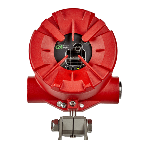
Fig. 2 FL500 UV/IR Flame Detector The FL500 is compatible with the General Monitors TA402A trip amplifier, FL802 controller, and other equipment that accepts 4 - 20 mA output. The device can be connected directly with alarm and suppression devices or switched input modules through integral relays. If the HART protocol is used with the FL802 controller, it is necessary to use the special HART signal (1.25 - 20 mA). -
Page 9: Led Operation Mode Definitions
Green LED = ON Green LED = OFF Alarm Low Yellow LED = OFF Red LED = Blinking slowly (1 Hz) Green LED = ON Green LED = OFF Alarm High Yellow LED = OFF Red LED = ON FL500 UV/IR Flame Detector... -
Page 10: Installation
No. 2 Philips screwdriver • 10 mm Allen wrench • Adjustable wrench Locations Use the information in Section 3.2.1 "Field of View" and Section 3.2.2 "Environmental Factors" to select the best location to install the device. FL500 UV/IR Flame Detector... -
Page 11: Field Of View
35’ 30’ 25’ 20’ 0° 45° 90’ - 45° 90’ 60° 75’ - 60° 60’ 15° 65° 50’ 40’ 30’ - 65° 50’ 40’ 30’ 30° 45° 55° 60° 65° Fig. 3 Heptane Field of View FL500 UV/IR Flame Detector... - Page 12 − 45° 80’ 50’ 15° 50° 35’ − 50° 35’ 55° 65’ 45’ 30° − 55° 65’ 45’ 60° 50’ 35’ − 60° 60’ 35’ 45° 50° 55° 60° 65° Fig. 4 Methane Field of View FL500 UV/IR Flame Detector...
- Page 13 − 40° 15° 50° 40’ 30’ 25’ − 50° 40’ 30’ 25’ 55° 20’ 30° − 55° 20’ 40° 60° 30’ 20’ 45° − 60° 30’ 20’ 50° 55° 60° Fig. 5 Methanol Field of View FL500 UV/IR Flame Detector...
- Page 14 35’ 25’ 15° − 40° 35’ 25’ 45° 25’ 20’ − 45° 25’ 20’ 30° 55° 60’ − 55° 60’ 40° 60° 50’ 45° − 60° 50’ 50° 55° 60° Fig. 6 Propane Field of View FL500 UV/IR Flame Detector...
- Page 15 40’ 30’ − 40° 40’ 30’ 15° 45° 30’ 25’ − 45° 30’ 25’ 50° 60’ 30° − 50° 60’ 55’ 60° 40° − 60° 55’ 45° 50° 55° 60° Fig. 7 Ethane Field of View FL500 UV/IR Flame Detector...
- Page 16 − 30° 40° 25’ − 40° 25’ 15° 45° 25’ 20’ − 45° 25’ 20’ 55° 55’ 30° − 55° 55’ 60° 45’ 40° − 60° 45’ 45° 50° 55° 60° Fig. 8 Butane Field of View FL500 UV/IR Flame Detector...
-
Page 17: Environmental Factors
Points downward to prevent dust and moisture from collecting on the optical window General Monitors does not recommend the use of cable shoes or crimps on any junction box or housing wiring terminals. Poor crimping can cause a bad connection when temperature variations occur. FL500 UV/IR Flame Detector... - Page 18 Installation Fig. 9 FL500 Outline Drawing, Front View Fig. 10 FL500 Outline Drawing, Side View FL500 UV/IR Flame Detector...
- Page 19 Installation Fig. 11 FL500 and Mounting Bracket, Side View Fig. 12 FL500 and Mounting Bracket, Top View FL500 UV/IR Flame Detector...
-
Page 20: Wiring
Installation Fig. 13 FL500 and Mounting Bracket, Rear View Wiring WARNING! An approved electrician must do electrical wiring. All wiring must satisfy the requirements of the applicable NEC, CEC, and local electrical safety codes. Install a conduit seal within 18 in. (46 cm) of the device enclosure. - Page 21 Installation Fig. 14 FL500 Housing and Base Remove the insulation from each wire to 0.25 in. (0.64 cm). Use the correct cables for the ambient temperature where the device is installed. Normally Open Switch Fault 2 Alarm Reset Fault C...
-
Page 22: Terminal Connections
All options can be set through Modbus, HART, or the DIP switch. Refer to Section 4.2 "Changing Device Settings" for instructions. Alarm High Relay Contact Relay Contact Position Relay (De-Energized) (Energized) Common Common Normally Closed Normally Open Normally Open Normally Closed FL500 UV/IR Flame Detector... -
Page 23: Tb2, Alarm Low Relay Connection
Function TB2 POS 11 RESET TB2 POS 14 TEST Multiple devices cannot be put in a daisy-chain configuration to use the Alarm Reset switch. Each latching Alarm Low and Alarm High output must be reset manually. FL500 UV/IR Flame Detector... -
Page 24: Analog Output, Modbus And Hart
0 mA output for a Fault condition. The Modbus protocol is used to configure the device or to find the status of the device. For information about Modbus, refer to the FL500 Modbus Communication Operating Manual (PN 10193214). -
Page 25: Cable Lengths
When the FL500 is used with a General Monitors Model IN042 card, the Alarm High resistor is set to 470 ohm and the EOL resistor is set to 5.6K. The EOL resistor is onboard the Model IN042 card and can be selected through the DIP switch. -
Page 26: Cable Termination In A Nonhazardous Area
Keep a separation of at least 3 ft (1 m) between instrument and other cables. An increased separation is necessary for long, parallel cable runs. Do not put instrument cable trenches close to lightning conductor earthing pits. FL500 UV/IR Flame Detector... -
Page 27: Operation
To change device settings through the DIP switch, do the following: Use a flat-blade screwdriver to remove the screws that attach the detector head to the base assembly. Find the DIP switch. Make the applicable switch assignments. Cycle power to the device. FL500 UV/IR Flame Detector... - Page 28 10-second Alarm Time Delay Alarm High Non-Latching Alarm High Latching Alarm Low Non-Latching Alarm Low Latching Alarm High Normal Energized Alarm High Normal De-Energized Alarm Low Normal Energized Alarm Low Normal De-Energized Alternate LED HART Enabled FL500 UV/IR Flame Detector...
-
Page 29: Using Modbus Or Hart
3.5 - 20 mA. This setting can only be changed through HART or Modbus. Settings for Modbus and HART can be changed through the DIP switch. For information about changing device settings through Modbus, refer to the FL500 Modbus Commu- nication Operating Manual (PN 10193214). -
Page 30: Alarm Test Feature
If the device does not sense the source, it sends Fault output and does the test again every 10 seconds. The Alarm Test feature can be used through Modbus and HART. Multiple devices cannot be put in a daisy-chain configuration to do testing for Alarm High output. FL500 UV/IR Flame Detector... -
Page 31: Maintenance
COPM Faults. General Monitors recommends that you clean the optical window and reflectors every 30 days at a minimum. Clean the optical window and reflectors more frequently for devices that are installed in dirty areas. FL500 UV/IR Flame Detector... -
Page 32: Annual Maintenance
Make sure that the mounting for all integral safety equipment, including but not limited to following components, is stable: • Power supplies • Control modules • Field detection devices • Signaling devices • Accessories connected to field and signaling devices FL500 UV/IR Flame Detector... -
Page 33: Storage
If possible, keep the device in the mold as shipped by the manufacturer. Install the red dust caps in the cable entry holes. Seal the device and a desiccant in a plastic bag. Seal the plastic bag inside another plastic bag. FL500 UV/IR Flame Detector... -
Page 34: Troubleshooting
10 seconds. If the signal (Alarm Low or Alarm Background UV radiation at analog output still shows High) with no known radiation device 16 mA or 20 mA, contact tech- at device nical support for more trouble- shooting. FL500 UV/IR Flame Detector... -
Page 35: Returning The Device For Repairs
CCTV, access control and social alarm systems. British Standards Institute, London, United Kingdom, 2011. • BS EN 61000-6-4:2007+A1:2011, Electromagnetic compatibility (EMC). Generic standards. Emis- sion standard for industrial environments. British Standards Institute, London, United Kingdom, 2007. FL500 UV/IR Flame Detector... -
Page 36: Specifications
Directional Dependence test. This result is from indoor benchtop testing with a Bunsen burner as the fire source, rather than the outdoor flame testing used to identify the field of view in Section 3.2.1 "Field of View". FL500 UV/IR Flame Detector... -
Page 37: Mechanical Specifications
(247 devices with repeaters) Baud rate: 2400, 4800, 9600, or 19200 bps Fully HART 7 FieldComm compliant. Refer to the HART FL500 HART Communication Operating Manual (PN 10193215). HART impedance RX = 50 K CX = 5 nF FL500 UV/IR Flame Detector... -
Page 38: Environmental Specifications
-67°F to 185°F (-55°C to 85°C) range Storage temperature range -40°F to 185°F (-40°C to 85°C) Humidity range 0% to 95% RH noncondensing False Alarm Source Distance from FL500 (ft) Trouble / False Alarm Direct sunlight Reflected sunlight Arc weld dc 190A, 7014 rod... -
Page 39: Approvals
Approvals Approvals CSA (CSA 18.70180732X), FM, ATEX (Sira 18ATEX1073X), IECEx (SIR 18.0026X), HART Regis- tered, SIL 3 suitable. FL500 UV/IR Flame Detector... - Page 40 For local MSA contacts, please visit us at MSAsafety.com Because every life has a purpose...
Need help?
Do you have a question about the FL500 and is the answer not in the manual?
Questions and answers