
Related Manuals for MSA Chillgard 5000


Summary of Contents for MSA Chillgard 5000
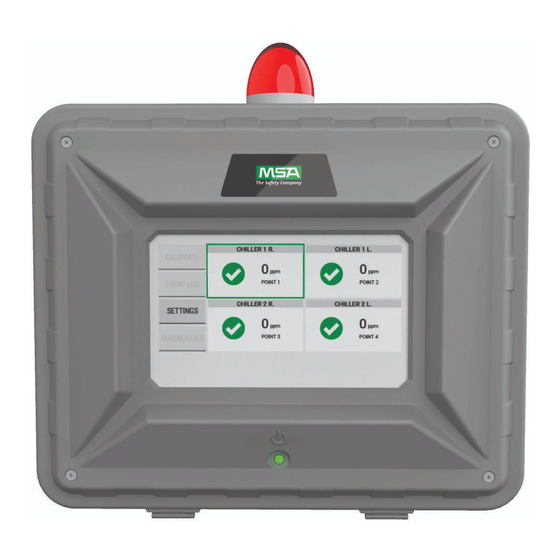
- Page 1 Operating Manual Chillgard 5000 Remote Display Order No.: 10214065/01 CR 800000043779 MSAsafety.com...
- Page 2 The warranties made by MSA with respect to the product are voided if the product is not installed and used in accordance with the instructions in this manual. Please protect yourself and your employees by following the instructions.
-
Page 3: Table Of Contents
Connection to the Chillgard 5000........ -
Page 4: Msa Permanent Instrument Warranty
The warranties made by MSA with respect to the product are voided if the product is not used and serviced in accordance with the instructions in this manual. Please protect yourself and others by following them. -
Page 5: Warnings And Cautions
Warnings and Cautions Warnings and Cautions The Chillgard 5000 Remote Display, hereafter also referred to as "the device", is an information module intended for indoor use in front of mechanical equipment rooms or commercial spaces where refrigerant equipment, such as centrifugal chillers, is used. The device is specified to support compli- ance with federal, state, and local safety codes that govern emissions. -
Page 6: Description
In case of an alarm, it is possible to acknowledge the audible alarm of the device, the Chillgard 5000 will remain in alarm. Refer to the Chillgard 5000 user instruction (P/N 10178535) to read more detail on alarm response. -
Page 7: Identifying Your Unit
4“ (101.6 mm) 6“ (152.4 mm) Fig. 3 Back of device Mounting locations (4″ x 6″ / 101.6 mm x 152.4 mm) Fig. 4 Right side of device 1/2″ conduit entry Approval and serial number label Chillgard 5000 Remote Display... - Page 8 Description Fig. 5 Left side of device 1/2″ conduit entry Fig. 6 Open device Input power Optional strobe CAN-IN CAN-OUT Chillgard 5000 Remote Display...
-
Page 9: Connection To The Chillgard 5000
Description Connection to the Chillgard 5000 The Chillgard 5000 Remote Display acts as the slave device in the network. The Chillgard 5000 monitor initiates and controls all communications on the network. There are two remote display outputs from the main unit. These will support two or more remote displays via daisy chaining. - Page 10 NOTE 1: If two Chillgard 5000 remote displays are configured using two CAN Bus connections as shown, jumper J5 must be removed from MIO board from Chillgard 5000 Monitor. Refer to the Chillgard 5000 Operating Manual, PN 10178535, for more information.
-
Page 11: Installation
Make sure the device is not located in areas that contain a flammable mixture of gas and air. Other- wise, an explosion can occur. Locate the device next to the entry door of the area where the Chillgard 5000 is installed and where it is easily visible to personnel entering the area where the Chillgard 5000 is installed. -
Page 12: Mounting Guidelines
Do not mount the device directly to chiller, piping, or piping supports. Mount the device: • Next to the entry door of the area where the Chillgard 5000 is installed and where it is easily visible to personnel entering the area where the Chillgard 5000 is installed. •... -
Page 13: Wiring And Grounding
CAN IN CAN OUT FROM Terminal block for DISPLAY CAN connections Fig. 12 Remote Display Wiring Diagram NOTICE Install enclosed ferrites with 2 turns on both of the power lines in order to meet local EMC regulations. Chillgard 5000 Remote Display... -
Page 14: Electrical Power Supply Requirements
(7) Connect the power wiring to the input terminals. Make sure the connectors are seated securely. (8) Connect the power ground wire to the earth ground terminal. (9) Close the enclosure. (10) Supply electrical power to the device. Chillgard 5000 Remote Display... -
Page 15: Initial Setup
Screen shot "Settings" The device comes without strobe, but with the audible horn activated. Before using the device, "Activate" to test the audible horn. In case of hearing a tone, go back to "inactivate". Screen brightness, Horn test) Chillgard 5000 Remote Display... -
Page 16: Attaching A Strobe
(2) Go to the Settings. Hit "Activate". There should be an audible and visual signal. If there is no audible or, after installation of the strobe, visual signal, contact MSA Safety Quality for repair/return. Chillgard 5000 Remote Display... -
Page 17: Maintenance
Housing material: Fiberglass Audible alarm: Minimum 70 dB at 12″ distance Power: 24V AC/DC Distance from main unit: max. 1000 ft/ 304 m Humidity: 0 to 95% non-condensing Dimensions: 11.3″ x 9.6″ x 3.1″ Weight: 4 lbs Chillgard 5000 Remote Display... -
Page 18: Ordering Information
Ordering Information Ordering Information Description Part Number Chillgard 5000 Remote Display 10204450 Accessories Description Part Number Strobe kit 10207966 Spare Parts Description Part Number Display spare 10174806 SD card 10206661 PCB board 10204443 Chillgard 5000 Remote Display... - Page 19 For local MSA contacts, please visit us at MSAsafety.com Because every life has a purpose...
Need help?
Do you have a question about the Chillgard 5000 and is the answer not in the manual?
Questions and answers