MSA Altair 4X User Instructions
Multigas detector
Hide thumbs
Also See for Altair 4X:
- Operating manual (72 pages) ,
- Quick start card (40 pages) ,
- Operating manual (66 pages)

Related Manuals for MSA Altair 4X


Summary of Contents for MSA Altair 4X
- Page 1 User Instructions Altair 4X® Multigas Detector Order No.: 10105903/06 Print Spec: 10000005389 (EO) CR: 800000065362 MSAsafety.com...
- Page 2 WARNING! These instructions must be provided to users before use of the product and retained for ready reference by the user. Read this manual carefully before using or maintaining the device. The device will perform as designed only if it is used and maintained in accordance with the manufacturer's instructions. Otherwise, it could fail to perform as designed, and persons who rely on this device could sustain serious injury or death. The warranties made by MSA with respect to the product are voided if the product is not installed and used in accordance with the instructions in this manual. Please protect yourself and your employees by following the instructions. Please read and observe the WARNINGS and CAUTIONS inside. For additional information relative to use or repair, call 1-800-MSA-2222 during regular working hours. For countries of Russian Federation, Republic of Kazakhstan and Republic of Belarus, the gas detector will be delivered with a passport document that includes valid approval information. On the CD with manual instruction attached to the gas detector the user will find the documents "Type Description" and "Test Method" - appendixes to Pattern Approval Certificate of Measuring instrument, valid in the countries of use. MSA is a registered trademark of MSA Technology, LLC in the US, Europe and other Countries. For all other trademarks visit https://us.msasafety.com/Trademarks. 1000 Cranberry Woods Drive Cranberry Township, PA 16066 USA Phone 1-800-MSA-2222 For your local MSA contacts, please go to our website www.MSAsafety.com © MSA 2024. All rights reserved...
-
Page 3: Table Of Contents
5.1 Technical Specifications 5.2 Factory-set Alarm Thresholds and Setpoints 5.3 Certification 5.4 Performance Specification 5.5 XCell Sensor Patents Ordering Information Cross Reference Factors Appendix 8.1 Start Up Sequence (Power on) 8.2 Fresh Air Setup (FAS) 8.3 Reset Screen Controls 8.4 Bump Test 8.5 Calibrations 8.6 Options Setup 8.7 Sensor Setup 8.8 Calibration Setup 8.9 Alarm Setup 8.10 Time and Date Setup Altair 4X Multigas Detector... -
Page 4: Safety Regulations
Failure to follow these warnings can result in serious personal injury or death. NOTE: This equipment has been tested and found to comply with the limits for a Class A digital device, pursuant to part 15 of the FCC Rules. These limits are designed to provide reasonable protection against harmful interference when the equipment is operated in a commercial environment. This equipment generates, uses, and can radiate radio frequency energy and, if not installed and used in accordance with the instruction manual, may cause harmful interference to radio communications. Operation of this equipment in a residential area is likely to cause harmful interference in which case the user will be required to correct the interference at his own expense. WARNING! Safety and Precautionary Measures • Check function (0.1 F unction Tests) each day before use. MSA recommends carrying out a routine inspection prior to each day's use. • Perform a Bump Test before each day's use (3.8 B ump Test) to verify proper device operation. The device must pass the bump test. If it fails the test, perform a calibration (3.9 C alibration) before using the device. • Perform a bump test more frequently if the device is subjected to physical shock or high levels of contaminants. Also, perform a bump test more frequently if the tested atmosphere contains the following materials, which may desensitize the combustible gas sensor and reduce its readings: ○ Organic silicones ○ Silicates ○ Lead-containing compounds Altair 4X Multigas Detector... - Page 5 Observe proper battery maintenance WARNING! Risk of explosion: Do not recharge device in hazardous area. Failure to follow this warning can result in serious personal injury or death. Use only battery chargers made available by MSA for use with this instrument; other chargers may damage the battery pack and the unit. Dispose of in accordance with local health and safety regulations.Use of the GALAXY Automated Test System is an alternate approved method for charging ALTAIR 4X instruments. Environmental Conditions A number of environmental factors may affect the sensor readings, including changes in pressure, humidity and temperature. Pressure and humidity changes also affect the amount of oxygen actually present in the atmosphere. Procedures for Handling Electrostatically Sensitive Electronics The device contains electrostatically sensitive components. Do not open or repair the device without using appropriate electrostatic discharge (ESD) protection. The warranty does not cover damage caused by electrostatic discharges. Product Regulations Follow all relevant national regulations applicable in the country of use. Warranty Regulations Altair 4X Multigas Detector...
-
Page 6: Warranty
STRICTLY LIMITED TO THE TERMS HEREOF. SELLER SPECIFICALLY DISCLAIMS ANY WARRANTY OF MERCHANTABILITY OR OF FITNESS FOR A PARTICULAR PURPOSE. Exclusive Remedy It is expressly agreed that Purchaser's sole and exclusive remedy for breach of the above warranty, for any tortious conduct of Seller, or for any other cause of action, shall be the replacement at Seller's option, of any equipment or parts thereof, which after examination by Seller is proven to be defective. Replacement equipment and/or parts will be provided at no cost to Purchaser, F.O.B. Seller's Plant. Failure of Seller to successfully replace any nonconforming equipment or parts shall not cause the remedy established hereby to fail of its essential purpose. Exclusion of Consequential Damage Purchaser specifically understands and agrees that under no circumstances will seller be liable to purchaser for economic, special, incidental or consequential damages or losses of any kind whatsoever, including but not limited to, loss of anticipated profits and any other loss caused by reason of non-operation of the goods. This exclusion is applicable to claims for breach of warranty, tortious conduct or any other cause of action against seller. Altair 4X Multigas Detector... -
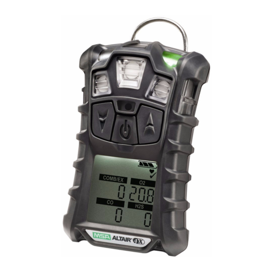
Page 7: Description
4. Horn 5. p Button 6. q Button 7. Button 8. Display 9. Alarm LEDs [4] 10. Belt Clip 11. Charging Connection 12. Screws [4] 13. Charge LED [red/green] Figure 1 Device Overview The device monitors gases in ambient air and in the workplace. The device is available with a maximum of three sensors, which can display readings for four separate gases (one Two- Tox Sensor provides both CO and H S sensing capabilities in a single sensor). While the device can detect up to 30% oxygen in ambient air, it is approved for use only up to 21% oxygen. The alarm levels for the individual gases are factory-set and can be changed through the Setup Menu. These changes can also be made through MSA Link software. Ensure that the latest version of the MSA Link software has been downloaded from MSA’s website www.msasafety.com. NOTE: If gas is present during Fresh Air Setup, the device will fail and enters Measure mode. Device Hardware Interfaces Device operation is dialog driven from the display with the aid of the three function buttons (Figure 1 ). Altair 4X Multigas Detector... - Page 8 alarm. The p button is used to reset peak, STEL TWA and acknowledge alarms (where possible) or access calibration in Measuring mode. It is also used as page up or to increase the values in Setup mode. LED Definitions Description GREEN The Safe LED flashes once every 15 seconds to notify the user that the device is ON and operating under the conditions defined in 3.7 S afe LED. This option can be turned OFF through the MSA Link software. The Alarm LEDs are visual indications of an alarm condition or any type of error in the device. YELLOW The yellow fault LED is a visual indication of an device fault condition. This LED turns ON with the following conditions: • Device memory error • Sensor Missing • Sensor Error RED/GREEN The charge LED is a visual indication of charge status. • RED: device is charging • GREEN: charge is complete Vibrating Alarm The device is equipped with a vibrating alarm. Backlight The backlight automatically activates when any front panel button is pressed and remains ON for the duration of the user- selected timeout. This ON/OFF duration can be changed through MSA Link software. Horn The horn provides an audible alarm. Altair 4X Multigas Detector...
-
Page 9: On-Screen Indicators
2 Description On-Screen Indicators 1. Graphic Symbols 2. Gas Type 3. Gas Concentration Figure 2 Display Alarm Symbol – Indicates alarm state. Motion Alert – Indicates Motion Alert is active. Bump Check Symbol – Indicates successful bump or cal. Indicates required interaction. Battery Condition – Indicates the battery charge level. Sensor Labels. Cal Gas Cylinder – Indicates cal gas must be applied. No Gas Cylinder – Indicates cal gas should not be applied and device must be exposed to fresh air. Hourglass – Indicates user should wait. Minimum – Indicates a minimum value or low alarm. PEAK Symbol – Indicates a PEAK reading or high alarm. STEL Symbol – Indicates a STEL alarm. TWA Symbol – Indicates a TWA alarm. End of Sensor Life Warning/Indicator Altair 4X Multigas Detector... -
Page 10: Battery Care
The duration of remaining device operation during a Low Battery -Warning depends on ambient temperatures. When the device goes into Low Battery Warning, the: • battery life indicator flashes • alarm sounds • alarm LEDs flash • display flashes "LOW BATT" and • device repeats this warning every 60 seconds and continues to operate until it is turned OFF or battery shutdown occurs. Battery Shut Down WARNING! If the battery shutdown alarm activates, stop using the device as it no longer has enough power to indicate potential hazards, and persons relying on this device for their safety could sustain serious personal injury or death. The device goes into battery shutdown mode 60 seconds before final shutdown (when the batteries can no longer operate the device): • "BATT ALARM" and flash on the display • Alarm sounds and lights flash; alarm cannot be silenced, • No other pages can be viewed; after approximately one minute, the device -automatically turns OFF. When battery shutdown condition occurs: 1. Leave the area immediately. 2. Recharge or replace the battery pack. Altair 4X Multigas Detector... -
Page 11: Viewing Optional Displays
• Operating beep is enabled • Device is on normal Measure Gases page • Device is not in battery warning • Device is not in gas alarm • Audible and visual options are enabled Viewing Optional Displays The Main Screen appears at device turn-ON. Optional displays can be viewed by pressing the q-- button to move to: Bump Mode 1. To select the Bump mode, press the button. 2. To move forward, press the q-- button. 3. To move backward to the Main page, press the p-- button. Peak Readings (PEAK page) The peak icon shows the highest levels of gas recorded by the device since turn-ON or since peak readings were reset. To reset the peak readings: 1. Access the PEAK page. 2. Press the p-- button. Altair 4X Multigas Detector... - Page 12 15 minute exposure of 35 ppm: (15 minutes x 35 ppm) = 35 ppm 15 minutes 10 minute exposure of 35 ppm and 5 minutes exposure of 5 ppm: (10 minutes x 35 ppm) + (5 minutes x 5 ppm) = 25 ppm 15 minutes This page can be de-activated through MSA Link. Time Weighted Average (TWA page) WARNING! If the TWA alarm activates, leave the contaminated area immediately; the ambient gas concentration has reached the preset TWA alarm level. Failure to follow this warning will cause over-exposure to toxic gases and persons relying on this product for their safety could sustain serious personal injury or death. The TWA icon appears on the display to show the average exposure since the device was turned ON or since the TWA reading was reset. When the amount of gas detected is greater than the eight-hour TWA limit: Altair 4X Multigas Detector...
-
Page 13: Sensor Missing Alarm
12 hour exposure of 100 ppm: (12 hours x 100 ppm) = 150 ppm 8 hours Time Display Current time appears on the display in a 12-hour format by default. A 24-hour format can be selected using MSA Link. Date Display Current date appears on the display in the format: MMM-DD-YYYY. Last cal page Displays the device last successful calibration date in the format: MMM-DD-YYYY Cal due page Displays the days until the device's next calibration is due [user selectable]. Motion Alert Page To activate or deactivate the Motion Alert feature, press the p button while the Motion Alert Activation page is displayed. When the Motion Alert feature is active, the Motion Alert symbol flashes every 3 seconds. The device enters pre-alarm when no motion is detected for 20 seconds. This condition can be cleared by moving the device. After 30 seconds of inactivity, the full Motion Alert alarm is triggered. This alarm can only be cleared by pressing the p button. Sensor Missing Alarm The device enters the Sensor Missing alarm if the device detects that a sensor is not properly installed in the device or is not functional. Altair 4X Multigas Detector... -
Page 14: Sensor Life Warning
The device displays the gas concentration in parts per million (PPM) or mg/m on the Measuring page until another page is selected or the device is turned OFF. WARNING! If an alarm activates while using the device, leave the area -immediately. Remaining in the area under such circumstances can cause serious personal injury or death. The device has four gas alarms for each toxic gas: • HIGH Alarm • LOW Alarm • STEL Alarm • TWA Alarm If the gas concentration reaches or exceeds the alarm set point, the device: • backlight turns ON • a vibrating alarm triggers • device displays and flashes the Alarm icon (HIGH alarm) • enters an alarm state. 2.10 Monitoring Oxygen Concentration The device monitors the oxygen concentration in ambient air. The alarm set points can be set to activate on two different conditions: • Enriched - oxygen concentration > 20.8 vol. % or • Deficient - oxygen concentration < 19.5 vol.% . While the device can detect up to 30% oxygen in ambient air, it is approved for use only up to 21% oxygen. Altair 4X Multigas Detector... -
Page 15: Monitoring Combustible Gases
The device has two alarm set points: • HIGH Alarm • LOW Alarm If the gas concentration reaches or exceeds the alarm set point, the device: • backlight turns on • a vibrating alarm triggers • device displays and flashes the Alarm icon (HIGH alarm) • enters an alarm state. When gas reading reaches 100% LEL or 5.00% CH4, the device enters a Lock Alarm state, the combustible sensor shuts down and displays “xxx” in place of the actual reading. This state can only be reset by turning the device OFF and ON in a fresh air environment. WARNING! A combustible gas reading of "100" or "5.00" indicates the atmosphere is above 100% LEL or 5.00% vol CH4, respectively, and an explosion hazard exists. Move away from contaminated area immediately. Failure to follow this warning can result in serious personal injury or death. In such cases, the device LockAlarm feature activates. Altair 4X Multigas Detector... -
Page 16: Operation
The device performs a self test and then goes to Fresh Air Setup: • all display segments are activated • audible alarm sounds • alarm LEDs light • vibrating alarm is activated. During the self test, the device checks for missing sensors. In the case of a missing sensor, the device displays the Sensor Missing screen and alarms until it is turned OFF. Otherwise, the turn-ON sequence continues. The device displays: • Alarm and display self test • Manufacturer name • Device name • Software version • Sensor discovery • Combustible gas type • Toxic gas units • Alarm set points ( , • Calibration values • Date and time display • Last cal date (if activated) Altair 4X Multigas Detector... - Page 17 • Fresh Air Setup option. Refer to flowchart in 8.1 S tart Up Sequence (Power on) Screen Displays during Start Up During the power-up sequence, all automatic page display timeouts are preset to a range from two to four seconds. Several sequences and screens occur during start up: Device Self Test The device performs a self test. Device Name and Software version Software version and device name display. Combustible Gas Type COMB/EX Name of Combustible Gas Type displays, e.g. BUTANE. Combustible gas type can be changed manually through the SENSOR SETUP menu or the MSA Link software. Toxic Gas Units Name of Toxic Gas Units displays (ppm or mg/m ). : Toxic units can only be modified through the MSA Link software. Altair 4X Multigas Detector...
- Page 18 NOTE: Alarm set points can be changed manually through the Setup menu or the MSA Link software. COMB/EX COMB/EX STEL and TWA Set points The preset STEL and TWA values for installed and activated sensors display. Calibration Values COMB/EX The preset calibration values for installed and activated sensors display. Time and Date The date displays in a month, day and year format. NOTE: In the event that the battery is fully discharged, the time and date reset. At startup, the user is prompted to enter the time and date. If the time and date information is missing, they are reset to [Jan-01-2008] with time stamp [00:00]. Last CAL Date and CAL Due NOTE: These display options can be set by MSA Link software. If these options are not set, these screens are not displayed. • By default Last Cal is activated. • By default Cal Due is deactivated. Altair 4X Multigas Detector...
-
Page 19: Measurement Mode [Normal Operation]
Failure to follow this warning can result in serious personal injury or death. COMB/EX Figure 3 Fresh Air Setup If this option is enabled, the device displays "FAS?", prompting the user to perform a Fresh Air Setup. 1. Press the p button to bypass the Fresh Air Setup. • The Fresh Air Setup is skipped and the device goes to the Measuring page (Main page). 2. Press the q button within 10 seconds to perform the Fresh Air Setup. • The device starts the FAS. • The screen shows a No Gas Symbol, a blinking hourglass, and all enabled gas sensor readings. • At the end of the FAS Calibration, the device displays "FAS OK" or "FAS ERR" along with the flags of the sensors that were outside of the FAS limits. All sensors that are within the FAS limits will be zeroed. Measurement Mode [Normal Operation] In Normal Operation mode, the user can check the Minimum and Peak readings prior to clearing the STEL and TWA values or performing a Span and Zero Calibration. Altair 4X Multigas Detector... -
Page 20: Device Setup
This page shows actual time and date settings of the device. Motion Alert (optional) This page allows the Motion Alert Feature to be -activated or deactivated. Using the three device buttons, the user can navigate through each sub-menu in a top/down sequence. Refer to 2.5 V iewing Optional Displays and 8.1 S tart Up Sequence (Power on) for detailed instructions on navigating through these screens. Device Setup This section describes the configuration options that are available through the Options Setup menus.The setup menus can be accessed only when the device is turned ON while pressing and holding the p button (see 8.2 F resh Air Setup (FAS) and 8.3 R eset Screen Controls). This mode can only be activated at device turn-ON. The operation is as follows: 1. Press and hold the p button while turning the device ON. a. Use the p and q-- buttons to enter the setup password. The default password is "672". 2. Press button to enter the setup menus. a. Incorrect password: device enters the Measure mode. b. Correct password: device continues/beeps three times. NOTE: The password can be changed through the MSA Link software. Altair 4X Multigas Detector... - Page 21 • Setup Time and Date (TIME SET) 23 • EXIT Sensor Setup Each sensor can be turned ON or OFF. For more information, see the flow charts in 8.7 S ensor Setup. COMB/EX Figure 4 Sensor Setup 1. To bypass this setup, press the q-- or p button; otherwise, continue as follows. 2. Press the button to enter the submenu. 3. Use the q-- or p button to change the option and confirm with the button. 4. Repeat this procedure for all other sensors. 5. After setting the last sensor, continue to Calibration Setup. Calibration Setup The user can change and set the calibration values for each sensor. It is also possible to select whether the Cal Due screen is displayed and set the number of days until the next calibration is due. For more information, see the flow charts in 8.5 C alibrations . COMB/EX Altair 4X Multigas Detector...
- Page 22 6. Press the button to store the value. HIGH ALARM settings for the first sensor display. 7. Press the q or p button to change the value. 8. Press the button to store the value. STEL ALARM settings (for toxic sensors only) display. 9. Press the q or p button to change the value. 10. Press the button to store the value. TWA ALARM settings (for toxic sensor only) for display. Altair 4X Multigas Detector...
-
Page 23: Data Logging
If the sensors have not warmed up yet, the countdown displays. The device then goes to Measuring mode. Data Logging Connecting device to PC 1. Switch ON the device and align the Datalink Communication port on the device to the IR interface of the PC. 2. Use the MSA Link software to communicate with the device. See MSA Link documentation for detailed instructions. Function Tests on the Device Alarm Test 1. Turn ON the device. Verify that: • all LCD segments are activated momentarily • alarm LEDs flash • horn sounds briefly Altair 4X Multigas Detector... -
Page 24: Safe Led
Failure to perform this test can result in serious personal injury or death. This test quickly confirms that the gas sensors are functioning. Perform a full calibration periodically to ensure accuracy and immediately if the device fails the Bump Test. The Bump Test can be performed using the procedure below or automatically using the GALAXY Test Stand. Equipment See accessory section for ordering information for these components. • Calibration Check Gas Cylinder • 0.25 liters/min. Flow Regulator • 1/8” ID Superthane Ester Tubing • ALTAIR 4X Calibration Cap Performing a Bump Test 1. From the normal measure screen press the q-- button to display “BUMP TEST?”. COMB/EX 2. Verify the gas concentrations displayed match the Calibration Check Gas Cylinder. If they do not, adjust the values through the Calibration Setup menu as described in 3.4 D evice Setup. Altair 4X Multigas Detector... -
Page 25: Calibration
5. Close the valve after bump testing. After the Bump Test completes, the device momentarily displays “BUMP PASS” or “BUMP ERROR” along with the label of any sensor that failed before returning to Measure mode. If the device fails the Bump Test, perform a calibration as described in 3.9 C alibration . The √ symbol will be displayed in the Measure mode for 24 hours after a successful Bump Test. Calibration The device can be calibrated either manually using this procedure or automatically using the GALAXY Test Stand (8.5 Calibrations). Calibration must be performed using a flow regulator with a flow rate set to 0.25 liters per minute. If a battery charging cycle is interrupted before it is completed (4 hours for a fully discharged battery), allow the device’s internal temperature to stabilize for 30 minutes before performing a Calibration. 3.9.1 Fresh Air Setup and Zero Calibration To skip the ZERO procedure and move directly to the calibration span procedure, push the p button. If no button is pushed for 30 seconds, the device prompts user to perform a Span calibration before returning to the Normal Operation mode. 1. Press and hold the p button in Normal Operation mode for three seconds. 2. If calibration lockout option is selected, enter password. ZERO screen displays. Password correct? Altair 4X Multigas Detector... - Page 26 “ZERO PASS” or “ZERO ERR” along with the flag of any sensor that failed. NOTE: During instrument zero calibration, the oxygen sensor is also span calibrated to 20.8% oxygen fresh air, adjusting the calibration curve as needed. During instrument span calibration, the O sensor’s accuracy is checked against a known oxygen gas concentration without adjusting the calibration curve. 3.9.2 Span Calibration To skip the Span procedure, push the p button. If no button is pushed for 30 seconds, the device returns to the Measuring mode. COMB/EX COMB/EX 1. Once the Zero is set, the SPAN screen displays. 2. Connect the appropriate calibration gas to the device. 3. Attach the calibration cap to the device. a. Insert tab on calibration cap into slot on device. b. Press calibration cap as shown until it seats onto device. c. Press both side tabs down onto device until they snap in. d. Ensure that the calibration cap is properly seated. e. Connect one end of the tubing to the calibration cap. f. Connect other end of tubing to the cylinder regulator (supplied in the calibration kit). 4. Open the valve on the regulator. Altair 4X Multigas Detector...
- Page 27 SPAN calibration starts. • After the SPAN calibration completes, the device momentarily displays COMB/EX COMB/EX “SPAN PASS” or “SPAN ERR” along with the label of any sensor that failed then returns to the Measuring mode. If a sensor is nearing its end of life, this "SPAN PASS" indication will be followed by the end of sensor life warning (♥ symbol). The ♥ symbol, and the gas type of the sensor nearing its end of life, will blink for 15 seconds when the device returns to measure mode. When in measure mode, the ♥ symbol is continuously displayed. If the span calibration is unsuccessful: • A sensor life indicator displays ( symbol and ♥ symbol) to show the sensor has reached its end of life and should be replaced. • The device will remain in alarm state until the p button is pressed. • The symbol and ♥ symbol will remain on the display until a successful calibration or sensor in question is replaced. A span calibration can fail for many reasons besides sensor at the end of his life. If a span calibration failure occurs, items such as remaining gas in the calibration cylinder, gas expiration date, security of the calibration cap, etc. should be verified and calibration should be repeated prior to replacing the sensor. Finishing Calibration 1. Close the valve on the regulator. 2. Remove the calibration cap. The calibration procedure adjusts the span value for any sensor that passes the ca-libration test; sensors that fail calibration are left unchanged. Since residual gas may be present, the device may briefly go into an exposure alarm after the ca-libration sequence is completed. Altair 4X Multigas Detector...
-
Page 28: Maintenance
ERROR CHARGE (97°F) to charge. Contact MSA if problem persists Missing Sensor Verify if sensor is properly installed SENSOR ERROR Device does not turn on Low battery Charge device Sensor warning Sensor is near the end of its life Sensor alarm Sensor has reached the end of its life and cannot be calibrated. Replace sensor and recalibrate. Live Maintenance Procedure - Replacing and Adding a Sensor NOTE: Leave the hazardous area prior to any maintenance or troubleshooting of the device. NOTICE • Before handling the PC board, ensure you are properly grounded; otherwise, static charges from your body could damage the electronics. Such damage is not covered by the warranty. Grounding straps and kits are available from electronics suppliers. • While device case is open, do not touch any internal components with metallic/conductive objects or tools. Damage to the device can occur. Altair 4X Multigas Detector... -
Page 29: Cleaning
7. Power ON the device. The device automatically senses that a new sensor is installed and displays the SENSOR DSCVRY screen. If the sensor replaced is the same as the previous sensor, the device starts up normally. Proceed to step 10 and calibrate the device. 8. If the sensor replaced is not the same as the previous sensor or this sensor channel was deactivated, the device automatically senses the difference when it is turned ON via SENSOR CHANGE on the display and prompts the user to accept or reject the change. "ACCEPT?" appears on the display. a. Accept the change with q button or reject with p button. b. Go into the sensor setup and turn on the appropriate sensor (3.4 D evice Setup) after being prompted for a password. 9. Calibrate the device after the sensors have stabilized. Allow sensors to stabilize at room temperature for at least 30 minutes before calibration (3.9 C alibration). WARNING! Calibration is required after a sensor is installed; otherwise, the device will not perform as expected and persons relying on this product for their safety could sustain serious personal injury or death. Cleaning Routine Cleaning: Clean the exterior of the device regularly using only a damp cloth. Do not use cleaning agents, as many contain silicone, which will damage the combustible sensor. Dust and Dirt Exposure: Use a dry, soft bristled brush to remove any dust or dirt that has accumulated on the apparatus, especially at the sensor openings. If there is a buildup of dust or dirt particles remaining in the sensor area after brushing, use a vacuum to remove remaining particles, but maintain at least 1/2" (1.3 cm) distance from the gas detector. Altair 4X Multigas Detector... -
Page 30: Storage
-4 to 122°F (-20 to 50°C) Extended operating range 50 to 95°F (10 to 35°C) While charging battery -40 to +140°F (-40 to 60°C) Intrinsic safety ambient temperature range (, IEC) Humidity 15% - 90% relative humidity, non-condensing, range 5% - 95% RH intermittent Atmospheric 800 to 1200 mbar pressure range Ingress IP 67 protection Measuring Combustible gases: Catalytic sensor methods Oxygen: Electrochemical sensor Toxic gases: Electrochemical sensor Measuring Combustible S-LC CO-H range Altair 4X Multigas Detector... -
Page 31: Factory-Set Alarm Thresholds And Setpoints
5 ppm 5 ppm 2 ppm 1 ppm 17.5ppm 10 ppm 19.5% 23 % 15.0% 25 ppm 100 ppm 1700 60 ppm CO-H2 25 ppm 100 ppm 1700 60 ppm 10 ppm 15 ppm 20 ppm NOTE: This device is not approved for use in atmospheres containing >21% oxygen. Certification See device label for the certification that applies to the specific device. IECEx TestSafe Australia Ex ia I Ma Ex da ia IIC T3 Ga - When Combustible XCell Sensor is installed Ex ia IIC T3 Ga - When Combustible XCell Sensor is not installed Ta=-40°C to +60°C Performance Specification Combustible Gas Range 0 to 100 % LEL or 0 to 5 % CH Altair 4X Multigas Detector... - Page 32 <10 second (normal temperature range) Sensor Cross-Sensitivity The oxygen sensor has no common cross-sensitivities. Carbon Monoxide Range 0 - 1999 ppm (0 - 1999 mg/m ) CO Resolution 1 ppm CO for 6 to 1999 ppm Reproducibility ±5 ppm O or 10 % of reading, whichever is greater (normal temperature range) ±10 ppm CO or 20 % of reading, whichever is greater Response time 90% of final reading (Typical) <15 seconds (normal temperature range) Test Gas Applied Concentration (PPM) Applied CO Channel % Cross-sensitivity Hydrogen Sulfide (H Carbon Monoxide (CO) Nitric Oxide (NO) Nitrogen Dioxide (NO Sulfur Dioxide (SO Chlorine (Cl Hydrogen Cyanide (HCN) Ammonia (NH Altair 4X Multigas Detector...
- Page 33 Chlorine (Cl Hydrogen Cyanide (HCN) Ammonia (NH Toluene Isopropanol Hydrogen (H Hydrogen Sulphide Low Concentration (H S-LC) Range 0 - 100 ppm H Resolution 0.1 ppm H Reproducibility ±0.2 ppm H S or 10 % of reading, whichever is greater (normal temperature range) ±0.5 ppm H S or 20 % of reading, whichever is greater (extended temperature range) Response time 90 % of final reading < 15 seconds (normal temperature range) Nitrogen Dioxide Range 0 - 50 ppm NO Resolution 0.1 ppm NO Reproducibility ±1 ppm NO or 10% of reading, whichever is greater (normal temperature range) ±2 ppm NO or 20% of reading, whichever is greater (extended temperature range) Altair 4X Multigas Detector...
-
Page 34: Xcell Sensor Patents
Response time 90% of final reading (Typical) <15 seconds (normal temperature range) Hydrogen Resistant CO (CO H2-RES) Range 0 - 2000 ppm CO Resolution 1 ppm CO Reproducibility ±5 ppm CO or 10% of reading, whichever is greater (normal temperature range) ±10 ppm CO or 20% of reading, whichever is greater (extended temperature range) Response time 90% of final reading (Typical) <15 seconds (normal temperature range) Hydrogen resistance <5% XCell Sensor Patents Combustible P/N 10106722 Patent Pending sensor sensor P/N 10106729 Patent Pending CO/H S sensor P/N 10106725 Patent Pending Altair 4X Multigas Detector... -
Page 35: Ordering Information
10095774 MSA Link Software CD-ROM 10088099 JetEye IR adapter with USB connector 10082834 Combustible sensor replacement kit 10106722 sensor replacement kit 10106729 CO/H S Two Toxic sensor replacement kit 10106725 Combustible EX-M Sensor replacement kit 10121212 Combustible EX-H Sensor replacement kit 10121211 S-LC/CO Sensor replacement kit 10121213 CO/NO Sensor replacement kit 10121217 S-LC/SO Sensor replacement kit 10121215 CO H -RES/H S Sensor replacement kit 10121214 Front Housing with integrated dust filters (charcoal) 10110030 Front Housing with integrated dust filters (fluorescent) 10110029 LCD Frame assembly (frame LCD, zebra strips, screws) 10110061 Sensors gasket, socket head cap screws (4x), self tapping (2x) 10110062 Altair 4X Multigas Detector... -
Page 36: Cross Reference Factors
Ethanol Ethylene Gasoline n-Hexane Hydrogen Isopropyl Alcohol Methane (5.0 Vol%) Methanol Pentane Simulant Pentane Propane (2.1 Vol%) Toluene Xylene Response Notes 1. For an instrument calibrated on Pentane Simulant, multiply the displayed %LEL value by the conversion factor above to get the true %LEL. 2. These conversion factors should be used only if the combustible gas is known. 3. These conversion factors are typical. Individual units may vary by +25% from these values. 4. The results are intended for guidance only. For the most accurate measurements, an instrument should be calibrated using the gas under investigation. Combustible Gas (with Optional EX-H Sensor) - Cross Reference Factors for Altair 4X General Purpose Calibration Using the Optional Heavy Hydrocarbon Sensor and Calibration Cylinder (PN 10045035) Set to 58% LEL Combustible Gas Multiply Reading By Acetone Methyl Ethyl Ketone (MEK) Nonane Xylene Altair 4X Multigas Detector... -
Page 37: Appendix
8 Appendix Appendix Start Up Sequence (Power on) Altair 4X Multigas Detector... -
Page 38: Fresh Air Setup (Fas)
8 Appendix Fresh Air Setup (FAS) From Start Up Sequence Press or wait 10 seconds Press key Press FAS OK? Begin Normal Operation Altair 4X Multigas Detector... -
Page 39: Reset Screen Controls
From Normal Operations (Main Page) Hold Hold for 3 seconds for 5 seconds Instrument off Button? CAL Mode Press BUMP Page To Calibration Press Press Button ? Press Measure Perform BUMP To Bump To Next Page Altair 4X Multigas Detector... - Page 40 8 Appendix From previous page COMB/EX Press Press COMB/EX Button ? Press Press Press Button ? Press Press Press Button ? Press Press Press Button ? Press Main Page Begin Normal Operation Set ON/OFF with Altair 4X Multigas Detector...
-
Page 41: Bump Test
8 Appendix Bump Test From Normal Operations (Main Page) Press No Button Button ? Button COMB/EX Begin Normal Operation COMB/EX Press Begin Normal Operation Altair 4X Multigas Detector... -
Page 42: Calibrations
8 Appendix Calibrations From Measure Page when is held for 3 seconds ZERO CAL Press Press Perform ZERO CAL? Press SPAN CAL Press Perform SPAN CAL? Press COMB/EX Return to Normal Operation CAL COMPLETE Altair 4X Multigas Detector... -
Page 43: Options Setup
8 Appendix Options Setup Password Correct? Button? Setup COMB/EX COMB/EX To Sensor Setup To CAL From Setup Date/Time Setup From From Alarm Setup Setup COMB/EX To Alarm Begin Normal To Time/ Setup Operation Date Setup Altair 4X Multigas Detector... -
Page 44: Sensor Setup
8 Appendix Sensor Setup Set Sensor with From Confirm Sensor with Setup Options COMB/EX COMB/EX Combustible To Calibration Setup Altair 4X Multigas Detector... -
Page 45: Calibration Setup
8 Appendix Calibration Setup Set Calibration Value with From Confirm with Setup Options COMB/EX Combustible Set ON/OFF with Confirm with To Alarm Setup Altair 4X Multigas Detector... -
Page 46: Alarm Setup
From Setup Options Set Alarms with Confirm Alarms with Set Alarms on or off COMB/EX COMB/EX Combustible Time/Date Setup 8.10 Time and Date Setup From Options Setup Set Time/Date with Confirm Time/Date with To Exit Setup Altair 4X Multigas Detector...
Need help?
Do you have a question about the Altair 4X and is the answer not in the manual?
Questions and answers