Raven CR7 Operation Manual
Hide thumbs
Also See for CR7:
- Quick start manual (35 pages) ,
- User manual (34 pages) ,
- Calibration manual (24 pages)
Table of Contents
Advertisement
Advertisement
Table of Contents

Related Manuals for Raven CR7


Summary of Contents for Raven CR7
- Page 1 CRX Operation Manual P/N 016-0171-664 Rev. C 06/18 E31464 Copyright 2018...
- Page 2 Raven Industries shall not be held responsible for any modifications or repairs made outside our...
-
Page 3: Table Of Contents
CR7 Overview ........ -
Page 4: Contents
CR7 Overview ........ - Page 5 Creating a Flag ..........40 Creating a Field Boundary, Do Not Apply Zone, or Application Zone .
-
Page 6: Manual Overview
MANUAL OVERVIEW This manual is designed for use with CRX software version 2.0. Updates for Raven manuals are available at the Applied Technology Division web site: http://portal.ravenprecision.com/ Sign up for e-mail alerts to receive notifications when Raven products updates are... -
Page 7: Important Safety Information
This is a safety-alert symbol. When you see the symbol below on the device, be alert because there is the potential for personal injury. Follow the recommended precautions and safe operating practices. INGRESS PROTECTION RATING The CR7 console is rated to IP65. -
Page 8: Crx Overviews
CR7 OVERVIEW DESCRIPTION The latest innovation from Raven is a small, yet powerful, field computer. The CR7™ is a 7” lightweight field computer with a simplified widget concept. Customizable in- job layouts, easily accessible settings, and ISO UT and Task Controller capabilities make this mighty unit a plug-and-play option for building an affordable system. - Page 9 SPECIFICATIONS • 2 CANbus Channels • 3 Serial Channels • One USB 2.0 Port • Gigabit Ethernet Port Connections • Wi-Fi 802.11 b/g/n • Bluetooth 2.1 with EDR and BLE 4.0 • Radar Speed Output • Keyed Power Start-Up and Shut-Down •...
-
Page 10: Cr12 Overview
Connection USB Port Power Button Ethernet Power and Port Connection CR12 OVERVIEW DESCRIPTION The CR12 is a larger version of the CR7 with a 12.1” capacitive touch screen, and an intuitive, tablet-style interface. CR12 utilizes the CRX operating software platform. - Page 11 • Anti-reflective though screen for optimal visibility • Clear and east to use • Integrated Wi-Fi module for easy remote support NOTE: Contact a local Raven dealer for information on additional features and options available for use with the CR12. SPECIFICATIONS • Two USB 2.0 •...
- Page 12 CR12 CONSOLE OVERVIEW FIGURE 3. CR12 Display Touch Screen FIGURE 4. Back of CR12 Console 2” RAM Mount Power Button USB Port (x2) Video Input (Not Used) Power Connection Ethernet Main Interface Video Output/ AUX CANbus Port Connector External Display...
-
Page 13: Care And Maintenance
-Any comments or feedback (include chapter or page numbers if applicable). -Let us know how long have you been using this or other Raven products. We will not share your email or any information you provide with anyone else. Your feedback is valued and extremely important to us. -
Page 14: Installation
3. Use the provided RAM mount arm to install the CRX inside the cab. 4. For additional cabling and connection assistance, refer to the CRX Installation Quick Guide. Additional system diagrams are available on the Raven web site. http://portal.ravenprecision.com/ QUICK START SETTINGS When starting the CRX for the first time a setup wizard will walk you through a setup process and, if desired, allow you to quickly start creating guidance lines. - Page 15 After powering up the CRX for the first time: 1. Select the desired language from the drop-down on the First Run Setup: Select Language screen. NOTE: Screen layout and button/widget location may vary slightly from the images shown in this manual. 2.
- Page 16 8. Press Next . The First Run Setup: Configure Machine Configuration window will open. 9. Select Quick Start to quickly create a simple machine configuration that can be edited later. If desired, select Create Detailed Machine Configuration to create a detailed machine configuration. After pressing Quick Start, the Machine Configuration: Quick Start window will open.
-
Page 17: Home Screen Overview
HOME SCREEN OVERVIEW The home screen is the first screen that opens after powering up the CRX and accepting all disclaimers. The home screen (see image below) provides basic options for starting New Jobs, accessing Machine Setup, and viewing maps. Status Bar Right Left... -
Page 18: Crx Settings Screen Overview
CRX SETTINGS SCREEN OVERVIEW STATUS BAR The status bar includes the following informational icons for quick reference. Note that the different icon colors indicate different status: Item Icon Description Number Indicates that there is a Bluetooth Bluetooth Connected device connected to the CRX. Indicates no GPS. -
Page 19: Crx Settings Screen Overview
Indicates that Slingshot functionality is turned off. Refer to the Slingshot Slingshot Disabled operation manual for additional information on Slingshot functionality. Indicates there is currently information being transmitted/received via Slingshot Transfer Slingshot. Refer to the Slingshot operation manual for additional information on Slingshot functionality. - Page 20 FOOTER ICONS The icons on the bottom of the screen provide easy access to settings, the UT, and also different view operation views. The table below describes the function of the icons in the footer. Icon Function Description Changes the run screen view to ground 3D View level.
- Page 21 SETTINGS ICONS Customizable Shortcut Bar The table below shows the icons from the settings screen and provides a brief description of their function. Note that the icons may appear over multiple screens. Scroll to the left or right to view the other screens. Icon Information Allows the user to add other icons to the Shortcut Library on the...
- Page 22 Icon Information Provides settings for Path Deviation Sensitivity, Center settings, and Reverse LED Indication. Provides setting options for Language, Time Zone, and Units of Measure. Allows the user to add a new machine or to update the existing machine configuration. Provides options that can be used as the input for master switch status of connected nodes.
-
Page 23: Machine Configuration
Icon Information The weather sensor provides support for add on components that measure temperature, humidity, etc. The information from the weather station can be recorded along with other job information. Allows the user to adjust On Line (OL) Sensitivity and the Line Acquire speed, configure all SmarTrax settings and run SmarTrax calibration. - Page 24 2. Press the Add Machine button . The Select Machine window will open. 3. Press Create New Machine. 4. Select the machine type. Available options are: • Traditional • Self Propelled • Articulated • Tracked NOTE: During machine configuration, if creating a self-propelled machine with an ISO boom connected to the CANBUS, select the ISO Boom instead of creating a new boom.
-
Page 25: Deleting An Existing Machine
16. Press Next . The Distance: Hitch Offset From Center window will open. 17. Enter the distance from the center of the machine to the center of the hitch. NOTE: This allows the CRX to calculate the correct position of the implement for determining the coverage rate and boom control functions. -
Page 26: Adding Drawn Equipment
3. Add Machine button . The Select Machine window will open. 4. Verify a machine is selected from the drop down. 5. Press Mount Equipment. 6. Press Create New Equipment. 7. Enter a name for the equipment. NOTE: If selecting a SCS or an item connected to the ISObus, skip to step 15. 8. -
Page 27: Iso Boom Configuration
1. On the settings page, press the Machine button. The machine Configuration window will open. 2. Press Add Drawn Equipment . The Select Cart window will open. 3. Select the desired cart type from the <Select Cart> drop-down or select Create New Cart. -
Page 28: Creating A New Grower, Farm, And Field
CREATING A NEW GROWER, FARM, AND FIELD Grower, Field, and Farm (GFF) data can be added to the CRX prior to starting a new job. 1. On the Settings screen, press GFF . The Grower Farm Field Information window will open. 2. -
Page 29: Delete Existing Grower, Farm, Or Field
1. On the CRX Settings screen, press GFF . The Grower Farm Field Information window will open. 2. Select the desired Grower, Farm, and/or Field from the appropriate drop-down. RENAME EXISTING GROWER, FARM, OR FIELD 1. Ensure the desired GFF is visible in the drop-down. 2. -
Page 30: Starting A Job
STARTING A JOB STARTING AN EXISTING JOB 1. On the home screen, press the Blue Arrow half way up the right side of the home screen. Select an Existing 2. Select the desired field from the Select Field list. Select Existing Field... -
Page 31: Start A New Job In A New Field
3. Select the desired job or selectty New Job to start a new job. New Job Existing START A NEW JOB IN A NEW FIELD 4. On the home screen press Next at the bottom of the screen or press the Blue Arrow and select New Job. - Page 32 11. Press Accept 12. Press Next . The run screen will open.
-
Page 33: Operation Planning
OPERATION PLANNING NOTE: Operation planning is only available on CR12. Operation planning is a method to define guidance lines (including tram lines) and headland application regions for an operation on a field. A operation plan can be selected to use for any job in the a field that has an operation plan association. Also, preconfigured guidance lines, headrows, and tramlines can be selected and applied to numerous jobs within an existing field boundary. - Page 34 2. Press Accept . The Edit Corners window will open. Corner Edit Corner Delete Corner Press and Drag Corner Name 3. If a corner is missing, press Add Corner. 4. The Edit screen allows the user to adjust the corner. Each corner is assigned a letter designation.
-
Page 35: Planning
6. Press Next . The Edit Baselines window will open. Each line is assigned a letter. For each baseline, select if the baseline is a straight line or a contoured line. NOTE: A baseline is a boundary that can be used to create a guidance lines and application zones. - Page 36 2. If desired, select Tramlines Setup. The Tramlines Setup window will open. NOTE: Tramlines are spaces between rows that are not planted so future operations in that field (such as spraying) will not drive over rows of crops. 3. In the S1: Enter the number of swaths before the first tramline or extra wheel width wills start.
- Page 37 1. Select one of the baselines. The Regions Settings window will open. 2. Adjust the desired settings. Setting Description Option This typically will only be used when the regions is not a Apply headed region. This will apply the tramline sequence to the Tramlines selected baseline.
- Page 38 Headland Enter the number of swaths needed for turn around. Passes Guidance lines will be created based on this setting. This is the extra space wanted between the baseline and the Offset first swath. This space will be a non-covered area around the edge of the field.
-
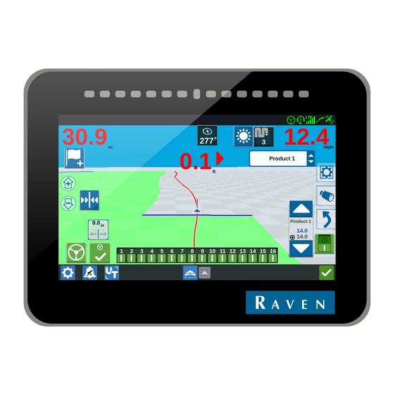
Page 39: Run Screen Overview
RUN SCREEN OVERVIEW The image below is an example of a run screen. This section provides basic information on run screen layout and widgets. Side Bar Side Bar Icons Icons RUN SCREEN OVERVIEW SIDE BAR ICONS There are many side bar icons available on the run screen. The table below shows the widget image as well as a brief description of function. -
Page 40: Widgets
Icon Function Description Provides information on existing scouting Scouting Object features and creating scout features. Select or deselect widgets that will display Widget Configuration on the run screen. Zoom In Zooms into the run screen map. Press zoom out to zoom out on the run Zoom Out screen map. -
Page 41: Widgets
Widget Name Function Altimeter Displays the machine elevation. Provides options for showing the applied Applied Area area(s). Product Rate Allows the user to adjust the product rate. Allows the user to select different Product Select products. Provides settings for configuring the Course Over Ground settings for the GPS course. - Page 42 3. Long pressing the widgets will open the widget bubble. This gives the user an opportunity to move, minimize, or delete a widget. It also provides options to adjust the settings for the product/feature widget. Minimize Widget Settings Move Widget Delete Widget...
-
Page 43: Scouting Objects
SCOUTING OBJECTS Scouting objects allows the user to create or mark different areas of the field to indicate obstacles, low spots, or field boundaries. The following options are available for Scouting Objects: • Field Boundary • Do Not Apply Zone •... -
Page 44: Creating A Field Boundary, Do Not Apply Zone, Or Application Zone
CREATING A FIELD BOUNDARY, DO NOT APPLY ZONE, OR APPLICATION ZONE Field boundaries indicate the edges of a field. Do not apply zones indicate an area in the field where application is not needed. Application zone indicates the outside edges of the desired application area. 1. -
Page 45: Creating Guidance Lines
CREATING GUIDANCE LINES 1. Select the guidance line icon. NOTE: The guidance line icon is the lowest icon on the right side of the screen and will be displayed as one of the available guidance line options. 2. Select the desired guidance line type. Widget Name Function... - Page 46 5. Select Accept to complete the line. 6. Select the guidance line icon along the right side of the screen. 7. Select the Edit next to the newly created line. The Edit Guidance Line window will open. 8. Enter a name for the guidance line. 9.
-
Page 47: Adjusting Section Control
2. Press in the cell to the right of the desired setting. 3. Enter the desired setting. NOTE: If using a Raven AccuBoom node, select the Use AccuBoom checkbox and the AccuBoom node will control the sections for the implement selected in the drop-down list. -
Page 48: Adjusting Rate Control Settings
4. Press Accept ADJUSTING RATE CONTROL SETTINGS 1. On the CRX Settings page, select Rate Control 2. Select the desired implement from the drop-down. 3. Select the cell next to the Prescription Map Look Ahead. 4. Enter the desired look ahead distance (in seconds). -
Page 49: Adjusting Settings
ADJUSTING SETTINGS DISPLAY SETTINGS To access display settings: 1. Press Display on the CRX Settings page. The Display Settings window will open. 2. The default settings for the display are Day Mode with the Screen Brightness and Lightbar Brightness at 100%. If desired, select Night Mode which switches the screen background and foreground colors and sets the Screen Brightness to 30% and Lightbar Brightness to 30%. -
Page 50: Serial Port Information
SERIAL PORT INFORMATION To access serial port information: 1. Press Serial Port on the CRX Settings screen. The Serial Ports - Port A window will open. Information for the Serial Port such as Baud Rate, Stop Bits, Parity, TX, and RX will display. If needed, select Detect Device to update the information. -
Page 51: Remote Support
5. After viewing and editing the GPS information, Press Accept REMOTE SUPPORT Remote support allows a Raven service specialist to remotely control the CRX. If remote support is needed to troubleshoot or access information on the CRX remote support will have to be enabled. Remote support on the CRX can only be completed via Slingshot. -
Page 52: Master Switch Configuration
MASTER SWITCH CONFIGURATION 1. Press Master Switch on the CRX Settings screen. The Master Switch Control Configuration window will open. 2. If desired, select the Require All On checkbox. This requires all selected inputs to be On for the Master to be on. Otherwise only one selected input needs to be on. 3. -
Page 53: Notifications
3. The default setting for the Reverse LED Indication is active. To deactivate the Reverse LED Indication, deselect the Reverse LED Indication checkbox. NOTE: Selecting or deselecting the Reverse LED Indication will change if the lightbar LEDs display to the right if to the right of the guidance line or to the left if to the right of the guidance line. -
Page 54: File Manager
FILE MANAGER The file manager allows the user to sort and move files (if desired). If the file is currently located on a USB stick, connect to the USB port on the back of the CRX. FILE TYPES The table below shows available file types on the CRX. Icon File Type Description... -
Page 55: Delete A File
4. Select the desired file(s) to be copied. 5. Press Copy to copy the selected file. The Copy Files window will open. Select OK to copy the file or Cancel to stop copying the file. 6. Press Accept after selecting the desired file(s). DELETE A FILE 1. - Page 56 2. Select USB from the left-most drop-down. 3. Navigate to and select the desired file type. For this example it is a feature unlock. 4. Select the desired file from the cell to the right. 5. Press Copy Files . The files will copy to the CRX.
-
Page 57: Loading And Running A Prescription Map
6. To verify unlocks have transferred successfully, navigate to the Features tab in the System Update field. The downloaded unlocks should now display with an open lock icon beside the feature. LOADING AND RUNNING A PRESCRIPTION MAP 1. Place the prescription map file (this will be a .dpf, .shp, .shx file) on a USB drive. Do not create subfiles for the prescription maps. - Page 58 5. Select the desired prescription map from the list. 6. Select Copy 7. Select Accept . A Copy Files window will open. 8. Press Accept to continue copying the file or press Cancel to select a different file. A Please Wait prompt will open while the files are being transferred. 9.
-
Page 59: Ejecting The Usb
11. Select Rate from the <Select Rate Column> drop-down. 12. If needed, adjust the units and conversion factor. 13. Press Accept . The Coverage to Implement Assignment window will open showing the Rx Control for the product. 14. Press Next to begin the job. -
Page 60: Software And Hardware Updates
SOFTWARE AND HARDWARE UPDATES SOFTWARE To check for CRX software updates via Slingshot: 1. Press Software Update on the CRX Settings page. The Update page will open. 2. If there is an update available via Slingshot it will be listed under the Slingshot Link column. -
Page 61: Downloading A Crx Update To Usb
5. If desired, press the About tab to view information about the CRX including the software version, when the software version was installed, Run Hours, and Total Run Hours. If desired, press Erase Data to reset the system and erase all data stored on the CRX. This includes all implements, Grower/Farm/Field data, and settings on the CRX. - Page 62 1. Press Software Update on the CRX Settings page. The Update page will open. 2. Select the Hardware tab. 3. If there is an update available via Slingshot it will be listed under on the Hardware Update page. To learn more information about the current version, select the information icon.
-
Page 63: Smartrax System Information
SMARTRAX SYSTEM INFORMATION The SmarTrax System Information page provides options for adjusting sensitivity, performing diagnostics, and general SmarTrax information. For SmarTrax operation and calibration information, refer to the appropriate SmarTrax Calibration and Operation Manual. -
Page 64: Feature Unlocks
The temporary unlock timer will continue until the unlock expires. Once the temporary unlock expires, the feature will be available using the activation package. Contact a local Raven dealer for additional assistance with temporary unlocks or feature activation. -
Page 65: Entering A Permanent Unlock
Job Code, Identification Number, and the countdown clock for the subscription. ENTERING A PERMANENT UNLOCK Permanent unlocks must be purchased through a Raven dealer. After purchasing the unlocks the files are loaded to the CRX with a USB drive. To install a permanent unlock on the CRX: 1. - Page 66 10. Select Copy 11. Restart the CRX after the files have transferred.
-
Page 67: System Shutdown
SYSTEM SHUTDOWN 1. To turn off the system, press the System Shutdown button or press the power button on the back of the CRX. A Confirm Shutdown window will open. 2. Press Accept to turn off the system or Cancel to return to the CRX Settings screen. -
Page 68: Limited Warranty
HOW CAN I GET SERVICE? Bring the defective part and proof of purchase to your Raven dealer. If the dealer approves the warranty claim, the dealer will process the claim and send it to Raven Industries for final approval. The freight cost to Raven Industries will be the customer’s responsibility. - Page 69 24 months from the date of retail sale. In no case will the Extended Warranty period exceed 36 months from the date the product was issued by Raven Industries Applied Technology division. This Extended Warranty coverage applies only to the original owner and is non-transferable.
- Page 70 HOW CAN I GET SERVICE? Bring the defective part and proof of purchase to your Raven dealer. If the dealer approves the warranty claim, the dealer will process the claim and send it to Raven Industries for final approval. The freight cost to Raven Industries will be the customer’s responsibility.
- Page 71 WHAT IS NOT COVERED BY THIS WARRANTY? Raven Industries will not assume any expense or liability for repairs made outside our facilities without written consent. Raven Industries is not responsible for damage to any associated equipment or products and will not be liable for loss of profit, labor, or other damages. The...
Need help?
Do you have a question about the CR7 and is the answer not in the manual?
Questions and answers