Raven ENVIZIO PRO Installation And Operation Manual
Multi-function field computer for growers
Hide thumbs
Also See for ENVIZIO PRO:
- Installation & operation manual (232 pages) ,
- Quick reference manual (16 pages) ,
- Installation & reference manual (32 pages)

Related Manuals for Raven ENVIZIO PRO


Summary of Contents for Raven ENVIZIO PRO
- Page 1 Envizio Pro™ and Envizio Pro II® Installation and Operation Manual P/N 016-0171-493 Rev. I 4/16/15 E24690 Copyright April 16, 2015...
- Page 2 GPS, GNSS, SBAS, etc.). Therefore, Raven Industries cannot guarantee the accuracy, integrity, continuity, or availability of these services and cannot guarantee the ability to use Raven systems, or products used as components of systems, which rely upon the reception of these signals or availability of these services.
-
Page 4: Table Of Contents
........................1 Hydraulic Safety ........................2 Electrical Safety ........................2 Chapter 2 Introduction................3 Envizio Pro Features ......................... 4 Speed Compensated Product Control and Datalogging ............4 On-Screen Guidance ......................5 Internal DGPS Receiver Options ..................5 Optional Features ........................ 7 Front Panel .......................... - Page 5 Closing Jobs and Power Down ..................54 Job Files ..........................55 Overview ..........................55 Starting a Job .......................... 56 Setting up a Job ......................... 56 Guidance Screen ........................62 Guidance Features ......................62 Envizio Pro™ and Envizio Pro II® Installation and Operation Manual...
- Page 6 Table of Contents Using Guidance Patterns ....................63 Product Control Features ....................66 Menu ............................72 Home ..........................72 Guidance Views ........................ 72 A-B Path Tools ........................73 Field Markers ........................77 Field Review Mode ......................78 Field Review Mode Tools ....................
- Page 7 ..........................137 Updates ........................... 138 File Maintenance ......................140 ..........................140 Vehicle Menu ......................... 141 Low Speed Mode ......................141 Guidance Width ....................... 141 Offsets and Implement Type Selection ................142 Envizio Pro™ and Envizio Pro II® Installation and Operation Manual...
- Page 8 Table of Contents Sections ........................... 147 Profiles ..........................152 Show All ..........................152 Chapter 8 Software Updates and File Maintenance ......153 Overview ..........................153 File Maintenance ........................154 File Outputs ........................154 Performing File Maintenance ..................155 File Structure .........................
- Page 9 Appendix B Testing Cables ..............203 Speed Sensor Extension Cable ..................... 203 Testing the Speed Sensor Extension Cable ..............203 Flow Meter/Encoder Extension Cable ................... 204 Testing the Flow Meter/Encoder Cable ................204 Envizio Pro™ and Envizio Pro II® Installation and Operation Manual...
- Page 10 Weather Station Activation Key ..................212 Weather Station Configuration ..................212 Using the Weather Station ..................... 213 Appendix E Updating CAN Nodes via the Envizio Pro ......215 Appendix F Updating the On-board DGPS Receiver ..........217 Required Components ......................217 Receiver Information .......................
- Page 11 Tools Menu ..........................254 File Maintenance ......................255 CAN Diagnostics ......................256 Guidance Patterns ......................... 257 Guidance Screen ........................257 Guidance Views ....................... 258 On-Screen Switch Box ....................258 viii Envizio Pro™ and Envizio Pro II® Installation and Operation Manual...
- Page 12 Table of Contents Field Review Mode Tools ....................259 A-B Path Tools ......................... 260 Field Boundary Tools ....................... 263 Alarms ........................... 264 AccuBoom™ ......................... 264 On-Screen Tools ......................265 AutoBoom® ........................... 266 AutoBoom® Status Indicator ................... 266 P/N 016-0171-493 Rev. I...
- Page 13 Table of Contents Envizio Pro™ and Envizio Pro II® Installation and Operation Manual...
-
Page 14: Calibration Reference Sheet
Calibration Reference Sheet Record the settings and calibration values used when programming the field computer and keep this sheet for future reference or when contacting a service technician. Circle the setting selected on the field computer for the following options: US (Acres) SI (Hectares) Turf (1000 Square Feet) -
Page 15: Unit Definitions And Conversions
1 kilometer (km) = 0.621 miles 1 Pound = 16 Ounces • • 1 inch = 25.4 mm or 2.54 cm 1 Pound = 0.45 Kilograms • 1 mile = 1.609 km viii Envizio Pro™ and Envizio Pro II® Installation and Operation Manual... -
Page 16: Important Safety Information
• Follow all safety information presented within this manual. • If you require assistance with any portion of the installation or service of Raven equipment, contact a local Raven dealer for support. • Follow all safety labels affixed to the system components. Be sure to keep safety labels in good condition and replace any missing or damaged labels. -
Page 17: Hydraulic Safety
CAUTION Hydraulic Safety • Raven Industries recommends that appropriate protective equipment be worn at all times when working on any hydraulic system. • Never attempt to open or work on a hydraulic system with the equipment running. Care should always be taken when opening a system that has been previously pressurized. -
Page 18: Introduction
The Envizio Pro and Envizio Pro II field computers are available with an optional internal DGPS (Differential Global Positioning System) receiver to simplify console installation and allow the system to be transferred to other vehicles over the growing season. -
Page 19: Envizio Pro Features
Advanced Features and Operation Envizio Pro Features The following descriptions offer a brief introduction to the capabilities of the Envizio Pro field computers and some of the optional features available for use with each of these systems. Speed Compensated Product Control and Datalogging Envizio Pro field computers are capable of monitoring or controlling product application via either a serial or CANbus rate control system. -
Page 20: On-Screen Guidance
Internal DGPS Receiver Options Both the Envizio Pro and Envizio Pro II offer options for an internal Differential GPS (DGPS) receiver to reduce cab clutter and simplify transfer of the control system between vehicles for use during various operations such as planting, spraying and harvesting. - Page 21 Slingshot Field Hub. Contact a local Raven or Slingshot dealer for subscription details and additional information. RTK. The Envizio Pro II internal receiver may be upgraded to receive Real-Time Kinematic (RTK) or a Continuously Operating Reference Station (CORS) network correction services to improve accuracy and repeatability for precision operations such as planting and strip tilling, or side dressing.
-
Page 22: Optional Features
Introduction Optional Features Flexibility of the Envizio Pro means that each field computer can be integrated into many existing Raven product control systems. The field computer can be used to control chemical injection and anhydrous ammonia applications, planting and harvesting operations or be integrated into an existing serial control system for mapping and guidance features. -
Page 23: Front Panel
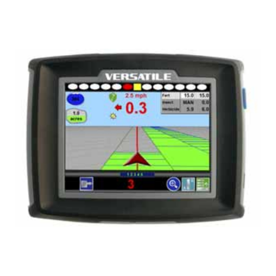
Chapter 2 Front Panel The front panel of the Envizio Pro features a touch screen for operator input, the power button and also provides convenient access to a USB port for file transfer and software updates. Envizio Pro User Interface FIGURE 2. -
Page 24: Usb File Transfer
PC to view and more permanently store this information. Use a USB flash drive with at least 512 MB of memory (maximum 4 GB) for transferring these files. Storage devices may be purchased at many retail locations or a local Raven dealer. 4 GB USB Flash Drive (P/N 524-0002-065) FIGURE 3. -
Page 25: Rear Panel
Chapter 2 Rear Panel The following is a brief overview of the connections and ports available on the back of the Envizio Pro field computers. The Rear Panel offers an additional USB Port as well as a port for connecting an optional wireless router for wireless communication. -
Page 26: Care And Use
Introduction Care and Use Refer to the following guidelines for proper care and use of the Envizio Pro field computer. CAUTION • Do not apply liquid or glass cleaner directly to the surface of the touch screen. Harsh chemicals may damage the touch screen. -
Page 27: Technical Specifications
Envizio Pro II 063-0173-301 1 GB (dual frequency GPS) Note: All Envizio Pro field computers with part number 063-0172-865, regardless of hardware revision, provide 512 MB of on board memory resources. Envizio Pro™ and Envizio Pro II® Installation and Operation Manual... - Page 28 Introduction Amp Connector Pin Definitions Main Amp Auxiliary Amp Connection Connection Main Amp Connector Auxiliary Amp Connector Battery Negative DGPS Transmit (Corrections In) Ext. Switch CAN Hi Ext. Switch CAN Lo CAN Hi DGPS Receive CAN Lo DGPS Transmit DGPS Receive (To External Devices) DGPS CTS DGPS RTS...
-
Page 29: Updates
Technology web site: www.ravenhelp.com At Raven Industries, we strive to make your experience with our products as rewarding as possible. One way to improve this experience is to provide us with feedback on this manual. Your feedback will help shape the future of our product documentation and the overall service we provide. -
Page 30: Installation
The following is intended as an overview of the installation process. These instructions cover the basic installation of the Envizio Pro and necessary hardware. For additional instructions on installing optional hardware with the field computer, refer to the instructions provided with the optional component(s). Instructions for building a CAN (Controller Area Network) system can be found in Chapter 4, CAN Networking and Diagnostics. -
Page 31: Kit Contents
Envizio Pro to Switch Pro Cable 115-0171-821 MBA-6 (Helix) Antenna 063-0173-317 Antenna Cable (20’) 115-0171-787 Mounting Kit (includes Hardware) 117-0171-132 Envizio Pro Installation and 016-0171-493 Operation Manual Envizio Pro Quick Reference Guide 016-0171-494 Envizio Pro™ and Envizio Pro II® Installation and Operation Manual... -
Page 32: Mounting The Field Computer
Installation Envizio Pro Kit Contents (Drawing Number 054-2040-004) FIGURE 1. P/N 016-0171-493 Rev. I... -
Page 33: Cable Platforms And Connections
To mount the Envizio Pro or Envizio Pro II field computer: Note: If the CAN Switch Box will be installed with the Envizio Pro field computers, use the mounting hardware provided with the CAN Switch Box. Refer to the CAN Switch Box Installation and Operation Guide for mounting instructions. - Page 34 Installation Cable Platforms and Connections Two cable platform options are available for use with the Envizio Pro field computers. Each platform offers a range of optional features which can be added to the control system at any time. NOTICE Please review the Raven CANbus Network...
-
Page 35: Generation 2 Cable Connections
Relay (P/N 415-1001-009) Terminals FIGURE 4. Batt + Batt - 12V Switched to Node Power To 12V Switched Orange Wire Key Switch Envizio Pro™ and Envizio Pro II® Installation and Operation Manual... -
Page 36: Dgps Antenna
CAN Switch Box kit (P/N 117-5020-001) Note: Contact a local Raven dealer for switch box options. Refer to the Raven CANbus Network Installation Manual for additional cabling information for the generation 2 cable platform. Generation 2 Cable Connection Diagram (Drawing Number 054-5000-001) FIGURE 5. - Page 37 Insert this connector into the ‘To Cab Cable’ on the chassis cable installed on the vehicle. Thread the connectors together to secure the connection. Route the end of the cable with two round connectors to the back of the Envizio Pro and connect to the main and auxiliary ports.
-
Page 38: Installing Optional Equipment
(P/N 115-0171-787) (P/N 115-0171-787) Note: The Envizio Pro II requires an MBA-6 helix antenna (P/N 063-0172-651) for use with RTK, GS, or OmniSTAR correction sources with the internal GPS receiver. Connecting External DGPS Receiver Systems Follow installation instructions included with any optional or additional external DGPS components before connecting to the field computer or related cabling. -
Page 39: Accuboom
Chapter 3 Installing Optional Equipment The following sections offer descriptions of optional hardware or configurations in which the Envizio Pro is capable of operating. Boom Sense Wire The boom sense wire may be connected to the master switch functions of the machine to allow seamless operation of vehicle master on/off and the field computer mapping feature. -
Page 40: Light Bar
Boom Sense Wire Note: Revision A or B cabin cables may not provide the purple boom sense wire. Contact a local Raven dealer for additional options or to replace the cable. Contact the machine manufacturer for more information on connecting the boom sense wire on the specific machine. -
Page 41: Smartrax
Error Error The Raven TM-1 Tilt Module compensates for any tilt of the vehicle from a level field condition. To supply tilt compensated GPS signal, the Raven TM-1 Tilt Sensor receives a raw DGPS signal from the DGPS receiver and outputs a tilt corrected signal to guidance devices or controllers. -
Page 42: Autoboom
Envizio Pro Gen 1 Cable Platform with Serial Control Console FIGURE 11. The Envizio Pro may be connected to a Raven serial control console via a serial port connection. In this configuration, the field computer is primarily used for the data logging, mapping, and guidance. - Page 43 Chapter 3 Use one of the following Raven RS-232 cables to connect the serial port on the back of the serial control console to the connector labeled ‘Console’ on the Envizio Pro interface cable. Description Part Number RS-232 cable - 3 ft.
-
Page 44: Can Networking And Diagnostics
CAN systems allow products to be added to a control system at any time. Up to four product control nodes or control channels can be connected to the Envizio Pro control system for any combination of liquid, granular, chemical injection or spinner control applications. -
Page 45: Can Diagnostics
Chapter 4 Envizio Pro Dual Product (Liquid/Granular) CAN Control System FIGURE 1. Envizio Pro™ and Envizio Pro II® Installation and Operation Manual... -
Page 46: Node Version Information
The field computer must be able to communicate with the CANbus system when monitoring or controlling product application. If configured as a CAN control console, the Envizio Pro should automatically establish communication with the boom/speed node, the AccuBoom, AutoBoom, or SmarTrax Terrain Compensation nodes (if installed), and up to four product control nodes via the CANbus. -
Page 47: Reset Canbus Defaults
CANbus (e.g. single product, dual product, motor control, planter control, etc.). Select the Information icon in the upper, right corner of the Home screen. Touch the icon on the About Envizio Pro screen to display the CAN Diagnostics screen. Touch the button to begin readdressing the product control nodes. -
Page 48: Additional Node Options
Service Mode The service mode is intended for use by a trained Raven technician and may be used to assist with troubleshooting and diagnostics. Contact a local Raven dealer for additional assistance. P/N 016-0171-493 Rev. I... -
Page 49: Can Troubleshooting
The following features or options may also be available via the CAN Diagnostics screen: Select Control Channels The Raven product controller node is capable of providing up to four product control channels on an Envizio Pro control system. By default, the product controller will make two control channels available to the field computer for controlling product application. - Page 50 Flow and speed sensors, as well as the control valve and boom valves, are used in the same fashion. CAN Node Off-line Errors Occasional reports have been received on Raven consoles sporadically losing communication with one or more CAN nodes. The most likely causes for this problem are: Corroded and/or open connections in the circuit.
- Page 51 Chapter 4 Envizio Pro™ and Envizio Pro II® Installation and Operation Manual...
-
Page 52: Startup, Initial Setup, And Setup Wizards
Setup Wizards Overview The first time the Envizio Pro field computer is powered up, the field computer will require some information about the machine, implement, and the type of applications, products and additional features connected to the system. The field computer gathers this information through a setup wizard which will prompt the user to input the required information to setup the computer for the first time. -
Page 53: Startup
See the Setup Wizards section on page 42 for a detailed description of the other available wizards. Startup The Envizio Pro field computer will take several seconds to power up and initialize the user interface, DGPS reception and the other features of the system. -
Page 54: Touch Screen Calibration
Note: The Envizio Pro does not require re-calibration of the touch screen every time the console is powered on. Use this procedure only if you are having difficulty with the user interface or the cursor appears in a different location than selected on the touch screen. -
Page 55: Initial Setup Wizard
Chapter 5 Initial Setup Wizard The initial setup wizard will automatically begin when the Envizio Pro is powered up for the first time. This wizard will step through the initial settings and calibration values required for operation of the field computer and control system. - Page 56 Startup, Initial Setup, and Setup Wizards Touch the Next icon to proceed with the initial field computer setup. Use the on-screen keypad to enter the implement, boom, or header width to the nearest inch [centimeter]. The value entered on this screen must be equal to the boom, implement, or header width which completes a field operation as the vehicle drives through the field.
-
Page 57: Setup Wizards
Chapter 5 Setup Wizards The setup wizards simplify the task of setting up the Envizio Pro control system for different products, implements or vehicles. Each setup wizard will display a series of prompts for which settings and calibration values will be required. -
Page 58: Product Section Setup Wizard
Startup, Initial Setup, and Setup Wizards Product Section Setup Wizard The product section setup wizard will guide the operator through configuring section widths and will require the following information: • Number of sections • Section widths • Section configuration • Desired section labels Using the Product Section Setup Wizard Touch the Product Section Setup Wizard icon. -
Page 59: Product Control Setup Wizard
By default, the product controller node is set to provide two control channels for the field computer. The initial configuration wizard will need to be completed before the number of control channels may be modified. Envizio Pro™ and Envizio Pro II® Installation and Operation Manual... -
Page 60: Using The Product Control Setup Wizard
Values, for instructions on refining the speed cal value. Note: The GPS speed over CANbus feature is only available with specific Raven speed sense nodes. This feature utilizes NMEA speed over ground data transmitted over the CAN network which eliminates the need for a separate, external speed sensor. - Page 61 Select the type of control valve which will be used on the first control channel. Touch the ‘Reset Valve Cal’ button to let the field computer insert the recommended initial calibration value. Raven Industries recommends the following valve calibration values for initial system setup. Control Valve Type...
- Page 62 Startup, Initial Setup, and Setup Wizards should be refined for the individual control valves installed on each specific machine. See Appendix A, Calculating the Calibration Values, for instructions on refining the valve cal value. Note: The Valve Advance button is only available if the assigned product node has software version 1.50 or higher.
- Page 63 Home screen. Note: During initial setup of the field computer, the Accept icon will only be displayed on the Setup Wizard Menu once all required wizards have been completed. Envizio Pro™ and Envizio Pro II® Installation and Operation Manual...
-
Page 64: Autoboom® Setup Wizard
Startup, Initial Setup, and Setup Wizards ® AutoBoom Setup Wizard If an optional Glide Series AutoBoom system has been installed, the AutoBoom setup wizard is available to calibrate and verify system settings during the initial setup. The AutoBoom setup wizard may require the following information: •... - Page 65 Chapter 5 Envizio Pro™ and Envizio Pro II® Installation and Operation Manual...
-
Page 66: Chapter 6 Basic Operation
B asic Operation CHAPTER C h a p t e r 6 Overview This chapter contains information regarding the basic operation of the Envizio Pro field computer in a CANbus control system, including: • • Home screen Guidance patterns •... -
Page 67: Gps Status
(WAAS/EGNOS) XP/G2 CORS Note: The standard GPS shield will be displayed if the Envizio Pro field computer cannot determine the type of corrections being sent from the DGPS receiver. The status icon on the Home screen will display: • Green if the status of GPS is okay. -
Page 68: Wireless Communications Status
Basic Operation Wireless Communications Status The current status of wireless communication is displayed along the top of the Home screen display. This icon will appear: • Gray if no wireless communications device is connected to the field computer. • Green if communication is okay. •... -
Page 69: Closing Jobs And Power Down
Chapter 6 Closing Jobs and Power Down Be sure to close any open job files before turning the field computer power off. The Envizio Pro should be powered down using the Shutdown icon on the Home screen. NOTICE Failure to properly close a job before turning off the field computer may result in a loss of application data or other information for that job. -
Page 70: Job Files
The Stop icon will be replaced with the Shutdown icon. Touch the Shutdown icon to power down the field computer. Job Files Overview The Envizio Pro stores field and product information in job files. In general, job files are created for each field and contain the following information: • Target rate (min and max) •... -
Page 71: Starting A Job
Starting a Job Before starting field guidance and creating a job file, the Envizio Pro field computers require the operator to check and verify job information. During this process, the operator may choose to create a new job or to resume an existing job as well as enable features and options to be used during the field operation. - Page 72 Basic Operation Touch the Accept icon in the lower, right corner of the screen to begin the job. See the Guidance Screen section on page 62 for more information. Touch the Cancel icon to end job setup without starting the job.
- Page 73 Touch the Cancel icon to return to the Start Job - Verify Settings screen without accepting the job name. Note: Job names stored on the field computer cannot begin or end with a space. Envizio Pro™ and Envizio Pro II® Installation and Operation Manual...
- Page 74 Basic Operation AccuControl Setup If an optional section control feature is available, touch the AccuControl button to create a new zone map or load a previously created plant zone map for the job. Note: Refer to Chapter 9, Using AccuBoom™, for more information about using AccuBoom. For details on using the AccuRow feature, refer to the AccuRow or OmniRow Calibration and Operation manual.
- Page 75 Touch the Delete Product icon to remove a product name from the list. Target Rate. The currently entered target rate is displayed on the Rate button. Touch the Rate button and use the displayed keypad to set a new target rate. Envizio Pro™ and Envizio Pro II® Installation and Operation Manual...
- Page 76 Basic Operation Prescription (Rx) Setup Touch the prescription icon to assign a prescription map to the selected control channel. Refer to the File Maintenance section on page 154 for assistance with transferring maps onto the Envizio Pro. ® AutoBoom Setup If an optional AutoBoom system is detected on the CANbus, the field computer will display the AutoBoom setup screen before accessing the Guidance display and features.
-
Page 77: Guidance Screen
Chapter 6 Guidance Screen During a field operation, or job, on the Envizio Pro field computers, the Guidance screen provides the application or coverage information and will likely be the most viewed screen during a job. Using DGPS coordinates, the field computer offers several field guidance tools to help reduce operator fatigue and minimize skips and overlaps during product application. -
Page 78: Using Guidance Patterns
SmarTrax™ Status Display If the optional SmarTrax system has been installed, the status of the system will appear on the Guidance screen. Using Guidance Patterns The following Guidance Patterns are available on the Envizio Pro: • Enhanced Last Pass •... - Page 79 Raven SmarTrax assisted steering systems. Contact a local Raven dealer for more information about Raven assisted steering systems available for use with the Envizio Pro field computer. The Enhanced Last Pass is well suited to provide guidance for irregular swaths due to irregular field boundaries, well heads, or waterways, etc.
- Page 80 Always be aware of sharp turns when using the Fixed Contour pattern if an assisted steering system such as Raven SmarTrax system is engaged. Contact a local Raven dealer for more information about Raven assisted steering systems available for use with the Envizio Pro field computer.
-
Page 81: Product Control Features
See the A-B Path Tools section on page 73 for additional assistance when using the A-B guidance line tools and features with the Pivot pattern. Product Control Features In addition to guidance features of the Envizio Pro, the Guidance screen displays product control information, coverage maps, as well as vehicle and GPS information. Previously... - Page 82 Basic Operation Tank or Bin Indicator - Displays the volume of product remaining in the tank or bin. Touch this area to display the Volume Configuration screen. See the Tank or Bin Indicator section on page 67 for more information. Area Covered - This indicator displays the area covered during the current job.
- Page 83 Tank Fill. If an optional tank fill system is installed and detected by the Envizio Pro, the field computer will display the fill system interface.
- Page 84 Basic Operation In Job Product Configuration Several product control settings and display options are available during a job by touching the rates area of the Product Rate Display. The following screen is displayed: The following information is displayed on this screen: Application information Selected product Control mode...
- Page 85 Configuration screen. Touch this button and use the displayed keypad to adjust the target rate. Display Options. Additional displays may be enabled or disabled with the options at the lower portion of the screen. Envizio Pro™ and Envizio Pro II® Installation and Operation Manual...
- Page 86 Basic Operation The following screen features are available on this screen: • On-Screen Rate Bump buttons - While in CAN product control mode, Rate Bump buttons may be used to increase or decrease the application rate of the selected product by a user defined rate “bump” value. Select the ‘Enable On-Screen Rate Bump Buttons’...
-
Page 87: Menu
Touching one of the following icons will switch the guidance view to the indicated perspective. The Down Field view is the initial view displayed when a job is started. This is a simulated perspective as seen from the cab of the vehicle. Envizio Pro™ and Envizio Pro II® Installation and Operation Manual... -
Page 88: A-B Path Tools
Basic Operation Switch to the Bird’s Eye view to change to a view from above the vehicle position. This view will display all of the same guidance features and tools as the down field view. A-B Path Tools The following tools and features may be found in the Menu when the Straight Line, Fixed Contour, or Pivot guidance patterns are active. - Page 89 Use the Re-calibrate A-B Line tool to re-calibrate the displayed path to the machine’s current position. Due to DGPS drift over time, this feature allows the operator to re-calibrate the A-B line to a known position in a field. Envizio Pro™ and Envizio Pro II® Installation and Operation Manual...
- Page 90 Note: The Nudge Feature is only available with A-B guidance paths (Straight Line, Pivot, Fixed Contour). The Nudge Feature works especially well with the Raven SmarTrax assisted steering systems. Contact a local Raven dealer for more information about these systems.
- Page 91 Touch the Nudge Left icon to move the guidance path to the right in 1 inch the guidance path to the left in 1 inch [2 cm] increments. [2 cm] increments. Envizio Pro™ and Envizio Pro II® Installation and Operation Manual...
-
Page 92: Field Markers
Basic Operation Field Markers Field markers allow the operator to mark locations such as well heads, rock piles, or points of interest during a field operation. Markers will be displayed during the operation and will allow the operator to view the marker information. To place a field marker: Touch the Menu icon in the lower, right corner of the guidance display. -
Page 93: Field Review Mode
To pan the display manually, touch the Field Review screen. The point touched will become the center of the field review display. Envizio Pro™ and Envizio Pro II® Installation and Operation Manual... - Page 94 Basic Operation Show Overlaps In addition to coverage, the field review mode can display application overlaps. The show overlaps feature displays areas where active sections entered a previously applied area and allows the operator to quickly review skips and overlaps on the same screen. With the show overlaps feature disabled, the field review mode displays the covered areas (including overlaps) in a solid green color.
-
Page 95: Field Boundaries
Field Boundary Once a field boundary has been completed, the Envizio Pro can calculate and display the area within the field boundary in acres (English) or hectares (Metric) in field review mode. Only one field boundary may be recorded per job. -
Page 96: Field Boundary Tools
Select the desired boundary to load into the current job. Note: Field boundaries exported from the Envizio Pro will be named either using the job file name entered when the job was started or the Zone Map name set for the map created during the job. - Page 97 Additional tools and features may be available in the Menu if the optional AccuBoom system is enabled for the current job. Refer to Chapter 9, Using AccuBoom™, for more information using the AccuBoom feature or contact a local Raven dealer for more information about the Raven AccuBoom system. Envizio Pro™ and Envizio Pro II® Installation and Operation Manual...
-
Page 98: Drift Shift
Basic Operation Drift Shift Note: The drift shift feature must be enabled prior to starting a job to allow the following features to be available during the field operation. Refer to Drift Shift section on page 134 for assistance with the drift shift settings. - Page 99 Set Reference Point Here. Touch the “Set Here” button to reset the reference point to the current vehicle location. The previous reference position will be lost. Envizio Pro™ and Envizio Pro II® Installation and Operation Manual...
-
Page 100: Prescription Maps And Variable Rates
Basic Operation Prescription Maps and Variable Rates With the optional variable rate application (VRA) feature enabled, the Envizio Pro is capable of using a prescription map to automatically change the target application rate. Envizio Pro field computer uses the shapefile format for prescription maps used to provide variable rate product control. -
Page 101: Applying Prescription Maps
Verify other job settings before beginning the job. Refer to the Starting a Job section on page 56 for more information. Envizio Pro™ and Envizio Pro II® Installation and Operation Manual... -
Page 102: Using Prescription Maps
Important warning and alert information is immediately displayed on the screen in the Alarms area. The Alarms area displays icons representing the portion of the system which requires the operator’s attention. In addition to visual alarms, the operator may wish to enable the audible alarms feature of the Envizio Pro field computers. -
Page 103: Alarms Area
Audible Alarms Audible alarms are enabled by default. To disable the notification tone or change available alarm settings, see the Alarm Settings section on page 116 to setup the Audible Alarms. Envizio Pro™ and Envizio Pro II® Installation and Operation Manual... -
Page 104: Tools Menu
T ools Menu CHAPTER C h a p t e r 7 Accessing and Navigating the Tools Menu After the initial setup wizards are complete, all settings and configurations are accessible by selecting the Tools icon on the Home screen. The Tools menu contains the following submenus: •... -
Page 105: Wizard Menu
If the light bar interface option is enabled, the Computer menu will also contain options for adjusting the brightness of the external light bar. See the Serial Port Configuration section on page 98, for more information on setting the light bar interface. Envizio Pro™ and Envizio Pro II® Installation and Operation Manual... -
Page 106: Vehicle Menu
Profiles allow the operator to setup GPS antenna heights and offsets as well as the swath width and section setup for each implement once and quickly reload a vehicle’s profile when transferring the Envizio Pro between vehicles. Show All Select the Show All icon to show an overview of the Tools menu. -
Page 107: On-Screen Keyboard
The character will not be entered in the character entry field until the touch is released. If the Envizio Pro is set to a language with diacritical signs (e.g. accent, grave, tilde, etc.), these special characters may be entered by: Touch and hold the desired basic character for approximately 3 seconds. -
Page 108: System Menu
System Menu The System menu contains the options for setting up how the Envizio Pro will interface with the product control hardware. The System menu also contains setup screens for the optional AccuBoom, AutoBoom systems. -
Page 109: Control Interface
None Select ‘None’ if the Envizio Pro will not be controlling product application (e.g. towing a disc, plow or rake). With this option selected, the Envizio Pro will only provide guidance for field operations. Raven Serial Console This option is used when the field computer is connected to another Raven product control console, such as a Raven SCS 440 or SCS 460, connected to the ‘Console”... - Page 110 Operation Manual for additional set up and operation information. CAN Planter Control Select ‘CAN Planter Control’ if the field computer will be interfacing with an optional Raven OmniRow system. The OmniRow system allows the field computer to control seed population rate and offers AccuRow, automatic ®...
- Page 111 Interfaces, for additional information. Yield Monitor Select ‘Yield Monitor’ if the field computer will be interfacing with an optional Raven SmartYield system to monitor and log yield and moisture data during harvest operations. Refer to the SmartYield Calibration & Operation Manual for additional information.
-
Page 112: Boom Master And System Options
Console’: Note: If the Envizio Pro is connected to a CANbus with another CAN controller (such as a Raven SCS 4400/4600) with AccuBoom, be sure the control interface option is set to ‘None.’ This option allows the field computer to monitor CANbus nodes without trying to control product nodes. In this configuration, the boom master options will not be displayed. -
Page 113: Serial Port Configuration
Refer to the Display section on page 135 to adjust the brightness of the external light bar via the field computer interface. Weather Station. Select this option to connect an optional WatchDog Sprayer Station to the Envizio Pro field computer. Depending upon the current system and connected controllers, the weather station may be connected to either ‘COM2/Console’... -
Page 114: Product Control
Tools Menu Product Control The Product Control menu displays the current settings and calibration values for the selected product. If additional product control nodes have been detected by the control system, touch the Select Product icon in the upper, right corner of the screen to cycle through detected product nodes or control channels. Select Product The Product Control Configuration screen contains several of the calibration numbers which the field computer... -
Page 115: Application Type
An optional OmniSeed authorization key is required for Gran 4 and Gran 5 application types to enable the field computer to control air seeder control systems. Contact a local Raven dealer for purchasing information and refer to the Updates section on page 138 to enter the activation code to unlock the Gran 4 and Gran 5 application type selections. -
Page 116: Speed
AccuFlow HP boost pump. Select this option to allow the operator configure specific boost pump control features for field operations. AccuFlow HP+. Select the AccuFlow HP+ option if controlling a Raven AccuFlow HP™ Plus system with the Vortex cooler for anhydrous ammonia applications. - Page 117 Note: The GPS speed over CANbus feature is only available with specific Raven speed sense nodes. This feature utilizes NMEA speed over ground data transmitted over the CAN network which eliminates the need for a separate, external speed sensor.
-
Page 118: Valve
If the dual loop control feature is enabled, the valve cal value will be replaced by the flow cal value. The valve cal value helps the field computer adjust the valve control response for slight differences between control valves and is required for product control. Raven Industries recommends the following calibration values for initial system setup. - Page 119 Calibration screen, but is still used to set the response of the system to the application system pressures. Note: Refer to the Feature Settings section on page 114 for information about enabling the standby pressure feature on the Feature Settings screen. Envizio Pro™ and Envizio Pro II® Installation and Operation Manual...
- Page 120 Tools Menu To access and set the Sgain value while operating in the standard control mode: From the field computer Home screen, select the Tools Menu icon. Select the Product Control icon from the System menu. Touch the Feature Settings button. On the Feature Settings screen, touch the dual loop control option to enable the feature and select the Accept icon to return to the Product Control Configuration screen.
- Page 121 To stop PWM output at any time during the calibration process, toggle the vehicle master switch to the off position. Note: Refer to the PWM Calibration Screen section on page 107 for more information on the PWM values configured using the calibration assistant. Envizio Pro™ and Envizio Pro II® Installation and Operation Manual...
- Page 122 Tools Menu Automatic Calibration. The automatic calibration mode will allow the field computer to automatically adjust the PWM output and attempt to determine the minimum, maximum and preset values. WARNING The PWM valve output will increase and decrease during the calibration procedure. Keep away from areas where product may be expelled and moving components and alert anyone around the equipment when performing...
- Page 123 PWM Frequency. This value sets the frequency of the pulses that are sent to the PWM valve. The default value is 122 Hz for Raven valves, or a value specified by the valve manufacturer. Envizio Pro™ and Envizio Pro II® Installation and Operation Manual...
-
Page 124: Calibration Settings
For recommended methods of calculating various calibration values, refer to Appendix A, Calculating the Calibration Values. If the field computer is connected to the optional Raven OmniSeed system for seeder control operations, refer to Appendix I, OmniSeed™ Calibration, for details on settings used with the OmniSeed feature. - Page 125 Enter the number of pulses sensed per one revolution of the fan or pump. These values are for monitoring purposes only. The field computer will not control based upon these calibration values or the monitored RPM of the pump or fan. Envizio Pro™ and Envizio Pro II® Installation and Operation Manual...
- Page 126 Tools Menu Tiered Boom Settings A tiered boom configuration has two or more booms stacked one directly in front of the other and may or may not have different sets of nozzles capable of applying different rates. Note: Specialized pluming, cabling and a relay box are required to utilize a tiered boom configuration. Generally, sprayers are not setup for this feature from the factory.
- Page 127 This feature may help to compensate for the time it takes a valve to adjust to a different rate or to fully open or close. Envizio Pro™ and Envizio Pro II® Installation and Operation Manual...
-
Page 128: Accuboom
Tools Menu Prescription (Rx) Default Rate. Set the Rx Default Rate at the Target rate for areas without Prescription information. The field computer will apply the default rate within any areas of a prescription map without a rate. Product control in Zero Rate zones will remain at zero. The Default Rate only affects areas where prescription rate information has not been entered. -
Page 129: Feature Settings
[1.1 km/h] while in automatic mode. To restart the system, cycle the master switch ‘Off’ then back ‘On.’ A speed of 0.7 mph [1.1 km/h] must be maintained for more than 10 seconds or the zero speed feature will reactivate. Envizio Pro™ and Envizio Pro II® Installation and Operation Manual... -
Page 130: Decimal Shift
Tools Menu Decimal Shift Use the decimal shift feature to increase the system accuracy for low application rates. In the standard mode, the field computer displays values to one decimal place. With decimal shift mode active, the field computer displays values to two decimal places. Note: If the decimal shift feature is changed, be sure to verify all calibration settings to ensure accuracy of the product control system. -
Page 131: Dual Loop Control
Alarm Settings screen also allows the operator to enable an audible alarm tone when the visual alarm notice displays. Note: Some alarm settings or features may be available only in specific control modes or when the field computer detects specific components or features on the CANbus. Envizio Pro™ and Envizio Pro II® Installation and Operation Manual... -
Page 132: Bin Alarm
The Flow Error Cal is replaced with the FER (Flow to Encoder Ratio) value when operating a Raven Sidekick Pro™. Refer to the Sidekick Pro Installation and Operation Manual for more information about operation with the Envizio Pro field computers. -
Page 133: Dual Flow (%) Percent
If the pressure falls below the entered value, the system will display an alert. Set the low supply pressure between 0 to 50 PSI [0 to 345 kPa]. Enter a value of zero to disable the low supply alarm. Envizio Pro™ and Envizio Pro II® Installation and Operation Manual... -
Page 134: Max Pressure Alarm
Tools Menu Max Pressure Alarm Note: The low supply alarm value will only be available if the control channel is configured for AccuFlow HP+ system control. Refer to Application Type section on page 100 for additional assistance with the application type settings. Enter the maximum pump pressure in PSI allowed for the AccuFlow HP™... -
Page 135: Autoboom
AutoBoom Touch this icon to display the AutoBoom Setup screen. See Chapter 10, Using AutoBoom®, for a brief overview of this feature on the Envizio Pro. Refer to the AutoBoom Calibration & Operation Manual for calibration and detailed operation instructions. -
Page 136: Reverse Sensing
Tools Menu Reverse Sensing Select this option to allow the field computer to automatically detect when the vehicle is traveling in reverse. When reverse speed is detected, the field computer will keep the previous orientation of vehicle indicator while updating the vehicle position. Note: If this feature is disabled, the guidance display will assume all vehicle motion is in the forward direction. -
Page 137: Gps Health
DGPS. Displays the source of differential correction being used. Note: If using the e-Dif correction source with the Envizio Pro internal receiver, the DGPS field will display AUTO. Version. The firmware version of the DGPS receiver. This information may not be available in all configurations or with some third party receivers. - Page 138 AOD. The Age of Data corrections is shown in seconds. This is the time since the last GPS message update has been received. Note: A Raven assisted steering system will disengage after a few seconds without a GPS message update. Elevation Mask. The elevation mask sets the minimum elevation of a satellite above the horizon which the field computer may use for differential correction.
- Page 139 Satellite corrections. AutoDetect GPS Touch the ‘AutoDetect GPS’ button on the GPS Health screen to allow the Envizio Pro to attempt to automatically detect GPS information coming from an external device. The autodetect feature is normally only required when interfacing with an external receiver or when receiving GPS information back from a SmarTrax or TM-1 Tilt Module.
-
Page 140: Differential
Envizio Pro internal receiver. Note: If the Envizio Pro is not able to detect the source or type of differential corrections received from the an external GPS receiver, or if corrections are routed from the internal GPS receiver through a Raven SmarTrax system or TM-1 Tilt Module, the Differential screen will be replaced by the Default Differential screen. - Page 141 Note: The Envizio Pro internal DGPS receiver is e-Dif capable. If connecting an external receiver to the Envizio Pro console, make sure that it is capable of using e-Dif prior to purchasing or authorizing an e-Dif code. Contact a local Raven dealer for more information about the optional e-Dif correction source and upgrades.
- Page 142 For areas with limited SBAS coverage, the Envizio Pro II dual frequency receiver features the NovAtel GL1DE as a GPS correction source option. In GL1DE only mode, the Envizio Pro II will use existing GPS or EGNOS satellites to locate the vehicle position within 20 in [50 cm].
- Page 143 The subscription status area displays the following subscription information when available: Note: If SmarTrax is connected to the Envizio Pro field computer, the operator must set the correction source to “Internal” before the following information will be available. Be sure to move the vehicle to a location with a clear view of the sky before contacting OmniSTAR for subscription information.
- Page 144 If SmarTrax is connected to the Envizio Pro field computer, the operator must set the correction source to “Internal” before the following information will be available. Be sure to move the vehicle to a location with a clear view of the sky before contacting a local Raven dealer for subscription assistance.
- Page 145 Baud Rate. Select the baud rate at which the correction messages are transmitted from the correction source. The default baud rate setting is 115200. Envizio Pro™ and Envizio Pro II® Installation and Operation Manual...
-
Page 146: Default Differential
Output Important: If a SmarTrax assisted steering system is connected to the Envizio Pro field computer, set the correction source to internal before making changes to the Envizio Pro internal receiver. To setup the type, frequency, and baud rate of message outputs from the built-in receiver, touch the Output icon. - Page 147 Messages sent out of the built-in receiver are sent out of the connector labeled ‘GPS Out’ on the auxiliary interface cable or chassis interface cable. Contact a local Raven dealer for more information. Baud Select the Baud Rate of the message strings sent from the built-in receiver.
-
Page 148: Source
Source Important: If a SmarTrax assisted steering system is connected to the Envizio Pro field computer, set the correction source to internal before making changes to the Envizio Pro internal receiver. The GPS Source screen allows the operator to select between the internal GPS receiver or an optional external receiver such as a Raven Phoenix 200/300. -
Page 149: Tilt Sensor
If the TM-1 Tilt Sensor is connected directly to the DGPS connector on the main interface cable (P/N 115-0171- 746) or chassis interface cable (P/N 115-0172-001), the Envizio Pro may be used to configure the TM-1. Touch the Tilt icon to access the Tilt Configuration screen. -
Page 150: Computer Menu
Tools Menu Computer Menu The Computer menu contains settings and preferences for the Envizio Pro field computer and display. Settings such as the display mode, brightness, language, light bar and display units are modified through the Computer menu. Features available with a USB flash drive, such as software updates and file maintenance are also accessed via the Computer menu. - Page 151 The External Light Bar adjustment will only display if the field computer is configured to control an external light bar. See the Serial Port Configuration section on page 98 to setup the external light bar interface. Envizio Pro™ and Envizio Pro II® Installation and Operation Manual...
-
Page 152: Region
Tools Menu Region Select the Region icon to modify display settings for the region in which the field computer will be used. The Region screen displays settings for the following: • Language • Display Units • Pressure Units Language The available languages are displayed in the scroll list. Select the desired language displayed on the field computer from the list. -
Page 153: Updates
Visit the Raven web site below and fill out the Activation Key Request form with the registration code received from the Raven dealer. www.ravenhelp.com Submit the request form to receive the activation key used to unlock the special feature on the Envizio Pro field computer. Note:... - Page 154 Raven dealer. www.ravenhelp.com Submit the request form to receive the activation key used to unlock the special feature on the Envizio Pro field computer. On the Envizio Pro, touch the Tools Menu icon on the Home screen.
-
Page 155: File Maintenance
Delete files from internal memory Raven recommends performing File Maintenance at least once a week and storing or backing up these files on a home or office PC. See Chapter 8, Software Updates and File Maintenance for details on using the File Maintenance feature. -
Page 156: Vehicle Menu
GPS antenna location on each vehicle as well as the swath width (guidance width) and the section configuration for the machine or implement. Once configured, vehicle profiles can be saved for later use, transferred to a USB drive, or loaded onto another Envizio Pro field computer. Low Speed Mode A filter is normally applied to the course over ground or heading information displayed by the Envizio Pro at speeds under 1.5 mph [2.4 km/h]. -
Page 157: Offsets And Implement Type Selection
DGPS antenna. Note: Be sure to enter positive values for each offset setting. All negative values entered will be reset to zero. Envizio Pro™ and Envizio Pro II® Installation and Operation Manual... - Page 158 Tools Menu The Raven Offsets Setup screen displays the currently calibrated values for the following antenna offsets: Fore or Aft Offset. The fore/aft offset is the distance of the boom or implement in front or behind the GPS antenna.The fore/aft offset must be measured perpendicular to the boom or implement width. See Figure 1 below.
- Page 159 To set the left/right value: Touch the current left/right value displayed on the Raven Offsets Setup screen.Use the keypad to enter the measured left/right value in inches [centimeters]. If the center line of the boom or implement is to the left of the GPS antenna, select the ‘Left of Center’...
- Page 160 Tools Menu Pivot to Rear Axle. (Articulated Vehicles Only) The pivot to rear axle value is the distance from the pivot point to the center of the rear axle. This value must be measured parallel to the direction of travel. Pivot to Front Axle.
- Page 161 The field computer will not recognize a negative value for any of the offset values. Be sure to enter sure to enter positive values for each offset. All negative values entered will be reset to ‘0.’ Envizio Pro™ and Envizio Pro II® Installation and Operation Manual...
-
Page 162: Sections
Tools Menu Touch the Next icon to proceed to the Drill Setup screen. The final value required for the tow between implement type is the distance between the drill hitch pin to the pivot point of the seed drill. Generally, the pivot point for a seed drill is the center of the rear frame axle. - Page 163 If the equipment is not capable of controlling individual sections, set the number of sections to 1 and enter the overall boom or implement width on the Section Width screen. Envizio Pro™ and Envizio Pro II® Installation and Operation Manual...
- Page 164 Tools Menu Configure the width of each section starting with the far left section. Use the on-screen keypad to enter the section width. Touch the Next icon to accept the entered value and advance to the next section to the right. To skip a section, enter a value of zero as the section width.
- Page 165 Configure Sections screen. Section Mapping The Envizio Pro field computer allows the operator to customize the section to switch mapping to the operator to quickly control multiple sections using a single switch. This feature also allows the operator to use a standard 10 section switch box to control an implement with more than 10 sections.
- Page 166 Tools Menu Manually Configure Sections If the boom or implement is not aligned end-to-end on the swath midpoint, the boom or implement sections will need to be manually configured. Select Manually Configure to begin locating boom or implement sections. The Section Location screen will be displayed.
-
Page 167: Profiles
System, Vehicle, Computer, and GPS menus and the individual pages accessible in each menu on one screen. Touch the Show All icon to display the Tools Menu overview. Envizio Pro™ and Envizio Pro II® Installation and Operation Manual... -
Page 168: Software Updates And File Maintenance
File Maintenance Overview The Envizio Pro File Maintenance feature allows the operator to manage job related files right in the cab. Raven recommends performing File Maintenance at least once a week and storing job related files on a home or office PC. Printable job reports may be created from files stored on a home or office PC. -
Page 169: File Maintenance
.dbf file extensions are all essential for the shapefile format to function correctly. To save memory on the field computer, the Envizio Pro only generates (if selected) the printable bitmap and shapefile reports when file maintenance is performed. For this reason, actual memory requirements for the USB drive will be greater than the disk space used on the field computer internal memory. -
Page 170: Performing File Maintenance
Open the Tools menu and select the File Maintenance icon in the Computer Menu. If the connected drive has not previously been used to transfer job files from the Envizio Pro, touch the icon along the right side of the screen to setup the required file structure. - Page 171 For example, if the operator selects “Job Files” and the “from Field Computer,” the Job Files screen will display similar to the following: Scroll List of Available Files File Maintenance Actions Use the following icons to perform the desired file maintenance actions: Envizio Pro™ and Envizio Pro II® Installation and Operation Manual...
- Page 172 Jobs exported to a USB flash drive using the SlingShot File type may be uploaded to the Slingshot web site using a home or office computer. Jobs exported using only the slingshot file type are not transferable to other Envizio Pro field computers. www.ravenslingshot.com Select the left icon to delete a selected file from the field computer or the right icon to delete all files of the selected type currently saved on the field computer.
-
Page 173: File Structure
USB drive: ePro Directory The main directory containing all of the information transferred from the field computer. The ePro directory keeps all Envizio Pro files separated from other files which may be stored on the flash drive. ePro The ePro sub-folder contains files used by the field computer. - Page 174 Slingshot job data package is exported to the USB flash drive. To save memory on the field computer, the Envizio Pro only generates (if selected) the printable bitmap and shapefile reports when file maintenance is performed.
-
Page 175: Updates
Chapter 8 Updates Software updates for the field computer will be available periodically from the Raven web site: www.ravenhelp.com Note: Screens and prompts may display differently depending upon the version of operating system and the PC or laptop on which the field computer update is downloaded. For additional assistance, refer to the user help information for your specific browser or operating system. - Page 176 Select the primary directory, or “root,” disk to extract the software update file. To successfully update the Envizio Pro, the update files cannot be placed in any sub-folders or directories. The “Unzip to folder” field in the self-extractor prompt should display similar to the example above where “F:\”...
-
Page 177: Applying Software Updates
Applying Software Updates Use the following procedure to apply software updates to the field computer. Before inserting the flash drive into the Envizio Pro, switch the power on and wait for the field computer to power up. From the Home screen, select the Tools menu icon and touch the Updates icon located in the Computer Menu. -
Page 178: Using Accuboom
CAN Switch Box If a Raven CAN Switch Box, or the Raven Switch Pro™ switch box, is installed with the field computer, the section switches must be in the ‘Accu’ position to allow AccuBoom control for the assigned sections. If the section switches are in the ‘On’... -
Page 179: Accuboom™ Setup
To enable the override during an AccuBoom enabled job: Toggle the ‘Master’ on the Raven CAN Switch Box to the Override position. The override timer will display a countdown for the override time in the switch box icon location. When the override time expires, the switch box icon will return. -
Page 180: Aggressiveness
Using AccuBoom™ If a CAN switch box or Switch Pro is not installed with the control system, the on-screen switch box may be used to enable the override feature. To enable the override during an AccuBoom enabled job using the on- screen switch box: Touch the on-screen switch box icon displayed in the lower, left corner of the Guidance screen. -
Page 181: Master Pressure
The master pressure feature requires a pressure transducer to monitor the pressure in the main product line. Contact a local Raven dealer for details or to purchase an optional pressure transducer. Disable the master pressure feature if a pressure transducer is not installed with the CANbus system. -
Page 182: Look Ahead
Using AccuBoom™ Look Ahead Set the AccuBoom Look Ahead setting to the number of seconds (determined by speed) the field computer is allowed to scan in front of the current vehicle position for zone map features. The On and Off Look Ahead settings may help to compensate for the time required to open or close control valves based upon the zone map. - Page 183 Touch the Accept icon and skip to step 7 if Standard AccuBoom is the desired mode of operation for this job. Proceed to step 6 to select a zone map for this job. Select the ‘Enable Zone Map’ option to enable the zone mapping mode. Envizio Pro™ and Envizio Pro II® Installation and Operation Manual...
-
Page 184: Accuboom™ Modes
Using AccuBoom™ The Start Job - Select Zone Map screen is displayed when the ‘Enable Zone Map’ option is enabled. Select the name of a previously saved zone map to use with this job and touch the Accept icon to return to the Start Job - Verify Settings screen. - Page 185 AccuBoom assigns a minimum of three boom or implement widths outside of the completed field boundary as a no-spray zone. The Envizio Pro will also disable section control features when the vehicle is outside of the recorded field boundary.
-
Page 186: On-Screen Switch Box
Guidance screen. Note: The on-screen switch box is not available if a Raven CAN switch box or Switch Pro switch box is connected to the CANbus. Touch this icon to access the section control feature screen to control individual sections or activate the feature override. -
Page 187: Using Zone Maps
Guidance screen. Note: Field boundaries created or exported by the Envizio Pro will be named using the job name or zone map name provided when the job was started. Shapefile boundaries may be renamed on a PC or laptop before importing the boundary onto the field computer. -
Page 188: Accuboom™ Mapping Tools
Using AccuBoom™ AccuBoom™ Mapping Tools The following tools are available via the Menu on the Guidance screen during an AccuBoom enabled job with zone mapping. Select the zone mapping tools to display AccuBoom and zone map tools available for the current job. -
Page 189: Creating An Accuboom™ Zone Map
On the Guidance screen, access the Menu and select the AccuBoom Boundary Tools icon. Select the Record Field Boundary button to begin recording a new AccuBoom field boundary. Record AccuBoom Field Boundary Envizio Pro™ and Envizio Pro II® Installation and Operation Manual... - Page 190 Using AccuBoom™ The Select Reference Point will display. The Reference Point is the point on the vehicle where the field computer will record the selected feature boundary. • Left and Right End of Section options set the Reference Point at the left or right end of the guidance width.
-
Page 191: Accuboom™ Zone Map Examples
The following screens are examples of AccuBoom maps displayed on the field computer. Field Review Mode While Recording a Boundary FIGURE 1. Spray Zone No-Spray Zone Field Review Mode with Completed AccuBoom™ Field Boundary and No-Spray Zone FIGURE 2. Field Boundary Envizio Pro™ and Envizio Pro II® Installation and Operation Manual... - Page 192 Using AccuBoom™ Guidance screen in Down Field View with Completed Field Boundary FIGURE 3. No-Spray Zone Spray Zone Field Boundary Field Review Mode with Completed AccuBoom™ Field Boundary and No-Spray Zone FIGURE 4. Field Boundary No-Spray Zones Spray Zone P/N 016-0171-493 Rev. I...
- Page 193 Chapter 9 Envizio Pro™ and Envizio Pro II® Installation and Operation Manual...
-
Page 194: Using Autoboom
C h a p t e r 1 0 Introduction The AutoBoom feature, used in conjunction with an Envizio Pro, adjusts the height of the booms automatically. Using the machine’s boom hydraulics, the AutoBoom parallel hydraulic system always keeps the hydraulic valves open, gently balancing the hydraulic cylinders and allowing the booms to raise or lower effortlessly. -
Page 195: Ultraglide
AutoBoom Operation Once properly calibrated, operation of the AutoBoom feature with the Envizio Pro is as easy as toggling the feature on and enabling height control for each boom. AutoBoom must be both On and Enabled for each boom before the system will manage boom height. The field computer does not require an active job to enable the AutoBoom feature. -
Page 196: Autoboom® Indicators
Using AutoBoom® ® AutoBoom Indicators The following sections offer examples of the AutoBoom status indicators which may be displayed on the Guidance screen during a job. The AutoBoom status display will appear differently depending on the capabilities of the AutoBoom system installed and connected to the field computer. Standard AutoBoom The following indicators may be displayed on the Guidance screen for a standard AutoBoom system: The AutoBoom Off indicator displays when the AutoBoom feature is turned off. - Page 197 Chapter 10 Envizio Pro™ and Envizio Pro II® Installation and Operation Manual...
-
Page 198: Troubleshooting
C h a p t e r 1 1 Troubleshooting Information This chapter contains information on troubleshooting possible issues with the Envizio Pro control system. Please read through this chapter before contacting technical support, as many common issues and solutions are covered here. -
Page 199: Setup Issues
AccuBoom with Raven serial console, • Console section switches • Section switches on Raven serial console must be in the 'Off' are in the 'On' position position. sections will not turn Envizio Pro™ and Envizio Pro II® Installation and Operation Manual... -
Page 200: Coverage Map Issues
Troubleshooting Issue Possible Cause Solution CAN AccuBoom will • Section switches are in the • Section switches for CAN AccuBoom must be in the 'On' 'Off' position position. not turn on • Make sure that the GPS receiver is operating properly and Date and time are •... -
Page 201: Gps Error Messages
Flow and speed sensors, as well as the control valve and boom valves, are used in the same fashion. Refer to the Raven CANbus Network Installation Manual for detailed troubleshooting procedures and information. -
Page 202: Appendix A Calculating The Calibration Values
Note: The GPS speed over CANbus feature is only available with specific Raven speed sense nodes. This feature utilizes NMEA speed over ground data transmitted over the CAN network which eliminates the need for a separate, external speed sensor. -
Page 203: Wheel Drive Speed Sensor
Count 10 full revolutions of the wheel while traveling in a straight path. The mark must stop with the chalk or tape in the same orientation that it began at the starting point. Calculating the Speed Cal with a Wheel Magnet Speed Sensor System FIGURE 1. Envizio Pro™ and Envizio Pro II® Installation and Operation Manual... -
Page 204: Speedometer Drive Speed Sensor
Calculating the Calibration Values Mark the stopping point and measure the distance between the starting and stopping marks on the ground in inches [dm]. Round to the nearest whole number. Note: This measurement is critical to the performance of the console. Measure Carefully. Be sure tire is properly inflated before measuring. -
Page 205: Liquid Applications
20 tips in a section with spacing of 40 inches would yield: × or a Section Width of 800 inches (approximately 67 feet). Enter 800 as the width for this section. Envizio Pro™ and Envizio Pro II® Installation and Operation Manual... -
Page 206: Meter Cal
Calculating the Calibration Values Band Spraying Adjustment To calculate the adjusted applied rate for band spraying applications, use the following formula: × ---------------------- - Where BR = the Broadcast Rate, BW = the band width, S = the spacing between the tips and AR = the Adjusted Rate for band spraying. - Page 207 Dispense exactly 10 gallons [38 L] through the flow meter as measured by the calibrated catch container. Important: Do not rely on graduation markings/numbers molded into the applicator tank. Envizio Pro™ and Envizio Pro II® Installation and Operation Manual...
- Page 208 Calculating the Calibration Values Toggle the section or master switch off. Read the value displayed on the field computer Total Volume button. This value should be within ± 3% of the meter cal value printed on the flow meter tag. To confirm accuracy, reset the Total Volume to 0 and repeat the above process several times.
-
Page 209: Valve Cal
The dead band digit is the allowable difference between the target rate and the actual application rate. The values range from 1 to 9, where 1 equals 1% difference and 9 equals 9% of the difference. Envizio Pro™ and Envizio Pro II® Installation and Operation Manual... -
Page 210: Valve Cal 2
Calculating the Calibration Values Valve Cal 2 Note: If the dual loop control feature is enabled, the valve cal 2 value will be replaced by the Sgain (pressure system gain) value. When a fast close valve is selected, the valve cal 2 value is utilized to enable a high resolution rate control for lower application rates. -
Page 211: Rate Cal
RFM 100 5 - 100 GPM [11.4 -380 L/min] RFM 200/ 200 Poly 15 - 200 GPM [56.8 - 760 L/min] RFM 400 25 - 400 GPM [94.6 - 1515 L/min] Envizio Pro™ and Envizio Pro II® Installation and Operation Manual... -
Page 212: Tiered Boom Settings
Calculating the Calibration Values Tiered Boom Settings A tiered boom configuration has two or more booms stacked one directly in front of the other and may or may not have different sets of nozzles capable of applying different rates. Note: Specialized pluming, cabling and a relay box or product controller node are required to utilize a tiered boom configuration. - Page 213 18 GPM [68.1 L/min] decreasing to 10 GPM [37.8 L/min] = only tier 1 enabled Max. Flow - 27 GPM 27 - 18 GPM 18 - 10 GPM Max. Flow - 102.2 L/min 102.2 - 68.1 L/min 68.1 - 37.8 L/min Envizio Pro™ and Envizio Pro II® Installation and Operation Manual...
-
Page 214: Granular Applications
Calculating the Calibration Values Granular Applications Boom Cal To calibrate section widths in inches [cm] for the granular application types: • For single section control systems, enter the total spread width as the boom 1 cal. • For dual section control systems, enter the left side spread pattern as boom 1 cal and the right side spread pattern as boom 2 cal. -
Page 215: Verification Of Spreader Constant
The target application rate must be entered in lbs/acre [kg/ha] as the rate cal value. Consult the equipment manual to ensure that the selected gate opening is capable of applying at this application rate. Note: The spreader constant must be recalculated anytime the gate opening is changed. Envizio Pro™ and Envizio Pro II® Installation and Operation Manual... -
Page 216: Spinner Rpm
Calculating the Calibration Values Spinner RPM For spinner box machines, use a product control node capable of controlling spinner speed. Valve Type Select the valve type currently used on the machine in which the field computer is installed. Application Select ‘Spinner’ as the application type. If spinner does not show up on the application rate, check that a CAN control node capable of controlling spinner applications is connected to the CANbus. -
Page 217: Additional Calibration Data
Reset Display Distance The current display distance, or odometer, registered by the field computer may be reset at any time. Refer to the Speed section on page 101 for more information. Envizio Pro™ and Envizio Pro II® Installation and Operation Manual... -
Page 218: Appendix B Testing Cables
T esting Cables APPENDIX A p p e n d i x B Speed Sensor Extension Cable Disconnect the extension cable from the speed sensor assembly cable. Hold the extension cable connector so that the keyway is pointing in the 12 o’clock position as shown below. Speed Sensor Extension Cable Pin Diagram FIGURE 1. -
Page 219: Flow Meter/Encoder Extension Cable
Verify the pin connection and voltage from the previous chart. If all of the cables test ‘good,’ replace the rate sensor. Note: After testing is complete, re-enter the correct cal values before starting an application. Envizio Pro™ and Envizio Pro II® Installation and Operation Manual... -
Page 220: Appendix C Wireless Communications & Remote Service
Remote Service ® The Envizio Pro, with a Slingshot Field Hub, allows the operator to wirelessly transfer application data back to the home or office and transfer prescription data from the office to the field. This feature also adds the ability to allow service technicians and support specialists to remotely control the field computer. -
Page 221: Wireless Status Screen
Touch the wireless status symbol displayed on the Home screen to display the Wireless Status screen. Site Information ® Touch the Site information button to view information from the Slingshot site. Envizio Pro™ and Envizio Pro II® Installation and Operation Manual... -
Page 222: Remote Service
The service technician will be able to determine whether a remote service session is necessary to assist with any issues encountered with the field computer. Contact a local Raven dealer or technical service provider before starting the remote service feature. -
Page 223: File Manager
Touching the “Re-Register” button will display the Re-Registration Warning prompt below. To re-register the Field Hub, touch the green check mark and proceed with the registration instructions to re-register the Field Hub. Envizio Pro™ and Envizio Pro II® Installation and Operation Manual... - Page 224 Wireless Communications & Remote Service To register: Touch the Wireless Status icon on the Home screen and select the Registration button. ® Wait while the field computer registers with the Slingshot web site and receives the registration code. It may take up to 15 minutes after the registration code is received for features to become fully enabled. Note: Be sure to enable the Remote Service and Web Access features if desired (recommended).
-
Page 225: File Transfer Settings
USB flash drive to transfer completed job information from the field computer to a home or office PC. Refer to Chapter 8, Software Updates and File Maintenance, for additional assistance with the File Maintenance features of the Envizio Pro field computers. Envizio Pro™ and Envizio Pro II® Installation and Operation Manual... -
Page 226: Appendix D Weather Station
• Wind Gust The Envizio Pro may only read information from one specific model of weather station. This unit is the WatchDog Sprayer Station Model 3349SS (P/N 117-0171-138) manufactured by Spectrum Technologies, Inc. This system may be ordered through any Raven dealer. For more information on this system contact Spectrum Technologies at (800) 248-8873. -
Page 227: Connecting The Weather Station
‘COM 3/Light bar’ on the auxiliary interface or chassis cabling. Weather Station Activation Key In order to use the weather station with the Envizio Pro, the weather module authorization code (P/N 077-0180-030) must be purchased from a Raven dealer. Once the code has been purchased and registered on-line, the activation key must be entered into the Envizio Pro. -
Page 228: Using The Weather Station
Using the Weather Station If weather station logging is enabled during an active job, the Envizio Pro will periodically record current weather conditions for the application report. To view current conditions or other weather station... - Page 229 Appendix D Envizio Pro™ and Envizio Pro II® Installation and Operation Manual...
-
Page 230: Appendix E Updating Can Nodes Via The Envizio Pro
A p p e n d i x E via the Envizio Pro Envizio Pro field computers with software version 2.2 or higher and CAN firmware version 10 or higher are capable of programming nodes on the CANbus directly through the field computer and connected cabling using a USB flash drive with the CAN Update program. - Page 231 Appendix E Touch the icon on the About Envizio Pro screen to display the CAN Diagnostics screen. Note: The current CAN Firmware version is displayed on the CAN Diagnostics screen. Insert the USB flash drive with the required .hex files into an available USB port on the field computer.
-
Page 232: On-Board Dgps Receiver
“BZZ” or “BFN” and are not required unless a specific issue encountered during operation has been addressed with the update. Please review the required components and read the firmware update procedure before starting the process. Contact a local Raven dealer for more information or additional assistance with any part of the firmware update. -
Page 233: Receiver Information
GS Satellite Subscription Note: For best service, verify that the Envizio Pro software is 3.7.1 or newer and the GPS firmware version is 6.04 or newer before purchasing a GS Satellite subscription. Ensure the GS activation code is entered before attempting to purchase the GS Satellite subscription. Refer to the Special Features Registration section on page 138 for assistance with entering an activation code. - Page 234 Click the Write Flash button to the right side of the main WinLoad panel. Immediately start the next step when the timer displays. Press and hold the Envizio Pro II power button until the unit shuts down. Press the power button to turn the field computer back on.
- Page 235 Touch the Accept icon to return to the main Tools Menu display. Reset the NMEA and Source settings as appropriate before beginning any field operations. Envizio Pro™ and Envizio Pro II® Installation and Operation Manual...
-
Page 236: Appendix G Tank Fill Monitor Calibration
T ank Fill Monitor APPENDIX A p p e n d i x G Calibration Overview An optional tank fill monitoring system is available to monitor the volume of product transferred from the nurse truck to refill the product tank. CAUTION The tank fill monitoring system does not control or automatically shut off the tank refilling... -
Page 237: Tank Fill Operation
When the field computer provides an alert, stop the nurse tank system to stop filling the product tank. On the Envizio Pro, touch the Stop Fill button to stop monitoring the product fill system. The Envizio Pro will adjust the Tank Volume Indicator for the selected product when the operator returns to the guidance screen. -
Page 238: Appendix H Blockage Monitoring Sensors
B lockage Monitoring APPENDIX A p p e n d i x H Sensors System Overview With the optional blockage sensor system, the field computer is capable of monitoring seed or product flow during field operations. If an obstruction is detected, the field computer will display information from the sensors to help the operator quickly locate the obstruction. -
Page 239: Configuring Blockage Sensor Loops
The default sensitivity value is 15. Refer to the Setting the Sensitivity section on page 227 for more information on setting and adjusting the sensitivity value for each sensor loop. Envizio Pro™ and Envizio Pro II® Installation and Operation Manual... -
Page 240: Configure Sensor Loops
Blockage Monitoring Sensors Configure Sensor Loops To setup the blockage monitoring sensor loops: Touch the Section Assignments button. The Sensor Section Setup screen for the first implement section will be displayed. Touch the Edit button corresponding to loop 1 and loop 2 and use the on-screen keypad to configure the number of sensors associated with the first implement section. -
Page 241: Blockage Monitor Status
When monitoring particularly dirty seed types or products, it may be necessary to clean each sensor in the loop when a the system indicates a sensor or sensors in the loop are dirty. Envizio Pro™ and Envizio Pro II® Installation and Operation Manual... -
Page 242: Setting The Sensitivity
Blockage Monitoring Sensors Communication Error Information. If a communication issue is encountered on either sensor loop, the status screen will display the value of the of the last sensor which the system is currently able to detect on the sensor loop. For example, “Loop 2 Sensor 8” means that sensor 8 on loop 2 is currently communicating correctly. - Page 243 Do not decrease the sensitivity value below the initial value. Check the indicated sensor locations and clear any obstructions and repeat the above procedure if the sensitivity value is decreased below the initial setting. Envizio Pro™ and Envizio Pro II® Installation and Operation Manual...
-
Page 244: Omniseed™ Calibration
The OmniSeed system also features a remote tank console that may be used while performing catch tests during meter priming and calibration. Refer to the Remote Calibration Console section on page 238 for additional information on using the tank console with the Envizio Pro field computer. Optional Ultrasonic Bin Level Sensors The OmniSeed system is capable of utilizing optional ultrasonic bin level sensors to monitor the seed bin level during seeding operations. -
Page 245: Omniseed Calibration Procedures
To access the pressure cal, fan cal and metered weight settings from the Home screen: Touch the Tools Menu icon and select the Product Control icon from the System menu. Next, touch the Calibration Settings button to display the Calibration Settings screen. Envizio Pro™ and Envizio Pro II® Installation and Operation Manual... -
Page 246: Optional Bin Pressure Sensor Calibration
Optional Bin Pressure Sensor Calibration Touch the Pressure Calibration button to access the Pressure Cal screen. Pressure 1 and 2 Cal. The Pressure Cal screen displays the current calibration setting for each pressure transducer connected to the product. Touch the Pressure Cal button and use the on-screen keypad to enter a different target pressure for the bin. -
Page 247: Metered Weight
Touch the Metered Weight button and use the on-screen keypad to enter the weight of the product in the units displayed on the keypad. Touch the Accept icon in the lower, right corner of the screen to save the entered weight and return to the Calibration Settings screen. Envizio Pro™ and Envizio Pro II® Installation and Operation Manual... -
Page 248: Section Setup
Section Setup The section set up for most seeder systems will require manual entry of offsets for sections based upon the relative location of seed control or any optional liquid sections. Note: Review the Section Setup section on page 148 for details on using the Section Setup Wizard. OmniSeed Granular and Liquid Section Configuration Example FIGURE 1. -
Page 249: Section Assignments
Sections must be assigned to the appropriate products to ensure that the field computer creates accurate coverage maps during field operations. To configure section assignments on the Envizio Pro: From the field computer Home screen, select the Tools Menu icon. -
Page 250: Section Switch Mapping
Section Switch Mapping The Envizio Pro provides the ability to customize the section control switch functions as necessary for various seeder configurations with or without liquid control sections. This capability allows the operator to control a full seeder and application system using a 10 section switch box or to customize switch functionality to control multiple sections with one switch. -
Page 251: Bin Level Sensor Calibration
Appendix I Bin Level Sensor Calibration Capacitive Bin Level Sensors The Raven OmniSeed system utilizes capacitive low bin level sensors to ensure products are available in each bin for the seeding operation. Note: The field computer monitors the capacitive low bin level sensors for low bin alarm and bin chaining conditions. -
Page 252: Optional Ultrasonic Bin Level Sensors
Optional Ultrasonic Bin Level Sensors The Raven OmniSeed system features optional ultrasonic bin level sensors which automatically detect the level of product remaining in each bin. The bin sensor for each of the first three products must be calibrated to accurately gauge the amount of product in the bin. -
Page 253: Remote Calibration Console
Note: When performing calibration with the remote tank console, the Envizio Pro field computer must be powered up. To ensure that the tank console programs the system properly, the field computer should not be used to navigate the calibration screens or the meter weight settings. The tank calibration kit requires a hydraulic drive system to connect the remote tank console. -
Page 254: Console Power
Console Power Press the blue power button to power up the remote tank console. Power Button If the console does not power up, check that all connections are secure and that the field computer is powered Note: The current program and software version numbers will be displayed while the console initializes during power up. - Page 255 With the remote tank console powered up, use the Next and Prev keys to select the desired bin and press the Enter key. Press the Begin key to start the bin calibration. Press the Next key to select the ‘Start Calibration’ option and then select the Enter key. Envizio Pro™ and Envizio Pro II® Installation and Operation Manual...
- Page 256 Press the Start key. WARNING The metering rollers will begin turning during the calibration procedure. Keep away from moving components and alert anyone around the air cart when performing the calibration process. Continue dispensing product until a sufficient weight is in the weight box or the weight box is full. Press the End key to complete the calibration.
-
Page 257: Using The Tank Console To Adjust Settings
When the field computer is initialized, all of the calibration values will need to be verified after the Decimal Shift feature is either enabled or disabled. Change settings as necessary. Envizio Pro™ and Envizio Pro II® Installation and Operation Manual... - Page 258 Use the INC or DEC keys to adjust the meter cal value and press the Enter key to set the meter cal value. Note: It is recommended to enter a meter cal of 60 when using the Envizio Pro for the hydraulic drive system.
-
Page 259: Troubleshooting
Press any key measurement • Be sure the min and max PW values are programmed correctly. Refer to the PWM Calibration Screen section on page 107 for more information. Envizio Pro™ and Envizio Pro II® Installation and Operation Manual... -
Page 260: Appendix J Serial Console Interfaces
2D/3D guidance features to current system operations. If the single product variable rate key (P/N 077-0180-031) has been activated on the Envizio Pro, the field computer may be used to variable rate product application via the existing serial console. -
Page 261: Serial Control Setup And Configuration
Serial Control Setup and Configuration Note: When the Envizio Pro is setup to interface with the Bogballe Calibrator Zurf, LH5000, or Amatron+ console, the “Profiles” feature within the field computer will be disabled. From the field computer Home screen, touch the Tools Menu icon. - Page 262 Serial Console Interfaces Offset Distance Calculation FIGURE 2. GPS Antenna Spreader Antenna/Spinner Offset Distance (measured) Spread Distance (from Chart) From the field computer Home screen, touch the Tools Menu icon and select the Offsets icon from the Vehicle submenu. Touch the Fore/Aft value on the Offsets Setup screen and use the on-screen keypad to enter the calculated total offset value.
-
Page 263: Accuboom™ Configuration
See Chapter 9, Using AccuBoom™, for more information on setting up and operating the AccuBoom feature on the field computer. Envizio Pro™ and Envizio Pro II® Installation and Operation Manual... -
Page 264: Operation
Serial Console Interfaces Operation When interfacing with the Calibrator Zurf, LH5000, or Amatron+ console, the field computer displays the user entered target rate and actual rate from the serial control console in the upper, right corner of the Guidance screen. Actual Rate Hopper Content Volume... -
Page 265: Area Covered & Coverage Mapping Information
If the single product variable rate key (P/N 077-0180-031) is activated, the field computer will send target rate information to the serial control console for automatic variable rate control and application. Envizio Pro™ and Envizio Pro II® Installation and Operation Manual... -
Page 266: Appendix K Reference Of Icons
R eference of Icons APPENDIX A p p e n d i x K Navigation The following icons will be used to navigate within the menu screens and to edit and save settings. Touch the Home icon when it appears to return to the Home screen. Any active jobs will continue in the background. -
Page 267: Home Screen
Guidance session. When the console is powered on or when Guidance is not active, the Shutdown icon will be displayed. Raven recommends using the Shutdown feature before pressing the power button. Information Touch the information icon in the upper, right corner of the home screen to display the software and image versions currently installed on the field computer. -
Page 268: Gps Status
(WAAS/EGNOS) XP/G2 CORS Note: The standard GPS shield will be displayed if the Envizio Pro field computer cannot determine the type of corrections being sent from the DGPS receiver. The status icon on the Home screen will display: • Green if the status of GPS is okay. -
Page 269: Wireless Communications Status
Select the Show All icon to show an overview of the Tools menu. The Show All screen is displayed each time the Tools menu is accessed. Envizio Pro™ and Envizio Pro II® Installation and Operation Manual... -
Page 270: File Maintenance
Reference of Icons File Maintenance To begin file maintenance from the Home screen: Touch the Tools Menu icon. Select the File Maintenance icon within the Computer menu. Note: Before performing file maintenance with a new USB flash drive, set up the required file structure on the connected USB flash drive by selecting the icon shown to the right. -
Page 271: Can Diagnostics
Readdressing Product Nodes section on page 31 for additional information. Touch this icon to update CAN nodes via the field computer. Review Appendix E, Updating CAN Nodes via the Envizio Pro, for more information on obtaining node update files and performing an update via the field computer. -
Page 272: Guidance Patterns
Reference of Icons Guidance Patterns The following icons represent the available Guidance patterns available for use with the field computer. The Enhanced Last Pass is well suited to provide guidance for irregular swaths due to irregular field boundaries, well heads or waterways, etc. The Straight (A-B) Line pattern is useful for applications in fields with row crops. -
Page 273: Guidance Views
Tap the automatic mode will toggle those sections back to automatic while leaving any manually controlled sections to the assigned mode. Double tap the master switch icon to toggle all section switches to the selected status. Envizio Pro™ and Envizio Pro II® Installation and Operation Manual... -
Page 274: Field Review Mode Tools
Note: When connected to an Envizio Pro field computer, the OmniRow system requires the Raven auxiliary planter node to control and map liquid product and liquid product sections during field operations. -
Page 275: A-B Path Tools
Be sure to transfer all necessary files to the field computer before beginning a job. A-B Lines stored on the field computer cannot begin with a space. Envizio Pro™ and Envizio Pro II® Installation and Operation Manual... - Page 276 Reference of Icons Setting A-B Points Straight (A-B) Line Pivot Fixed Contour To create a New A-B Line, the operator must set A and B Set A points. The following icons and tools may be used to set a New A-B Line. Touching the Set A icon will place the first, or A, point of the path at the vehicle’s current location.
- Page 277 The Nudge Feature allows the operator to fine tune the displayed path for actual field conditions. The Nudge Feature works especially well with the Raven SmarTrax assisted steering systems. Contact a local Raven dealer for more information about these systems.
-
Page 278: Field Boundary Tools
Reference of Icons Field Boundary Tools The following icons will be used while creating a field boundary. Touch the Boundary Tools icon to display boundary tools available for the current job. A previously recorded boundary can be loaded into the current job file by selecting the Load Field Boundary icon in the Menu. -
Page 279: Alarms
Touch the Record Field Boundary icon to create a new AccuBoom field boundary. With zone mapping mode enabled, AccuBoom will assign a minimum of three boom widths outside of the completed boundary as a no-spray zone. Envizio Pro™ and Envizio Pro II® Installation and Operation Manual... -
Page 280: On-Screen Tools
Reference of Icons On-Screen Tools While recording a zone map feature, the following icons may be displayed on the Guidance screen. Pause Select the Pause button displayed on the Guidance screen to temporarily interrupt recording the current zone map feature. Pause Pause No-Spray Pause Field... -
Page 281: Autoboom
If operating with an UltraGlide AutoBoom system, the set Sensor Height is displayed in the Status Display. If an optional center rack sensor is installed, the actual height of the center rack will be displayed in this area. Envizio Pro™ and Envizio Pro II® Installation and Operation Manual... - Page 282 Safety 2 Enabling AccuBoom™ Boom Cal 190, 199 Enhanced Last Pass Boom Sections Envizio Pro Startup 38 Envizio Pro Features See Features Calibration Error Messages Additional Data 202 GPS 186 Entering Bin Level 202 Job 185 Entering Tank Volume 202...
-
Page 283: Chapter 1 Important Safety Information
See Prescription (Rx) Settings Product Setup 59 Resume an Existing Job 58 Setting up a Job 56 Start a New Job 58 Screens Starting a Job 56 Guidance Screen 62 Envizio Pro™ and Envizio Pro II® Installation and Operation Manual... - Page 284 Index Home Screen 51 Verifying Flow Rate Limits Section Assignments Volume Serial Port Configuration Bin Level 113 Setup Wizard Menu Tank Volume 113 Volume and Area Settings AutoBoom™ Setup Wizard 49 Product Control Setup Wizard 44 Section Setup Wizard 43 Special Features Registration Speed Cal Weather Station...
- Page 285 Index Envizio Pro™ and Envizio Pro II® Installation and Operation Manual...
-
Page 286: Limited Warranty
Bring the defective part and proof of purchase to your Raven dealer. If the dealer approves the warranty claim, the dealer will process the claim and send it to Raven Industries for final approval. The freight cost to Raven Industries will be the customer’s responsibility. The Return... - Page 287 How Can I Get Service? Bring the defective part and proof of purchase to your Raven dealer. If the dealer approves the warranty claim, the dealer will process the claim and send it to Raven Industries for final approval.
Need help?
Do you have a question about the ENVIZIO PRO and is the answer not in the manual?
Questions and answers