Raven CR Series Operation Manual
Hide thumbs
Also See for CR Series:
- Operation manual (71 pages) ,
- Manual (9 pages) ,
- Installation manual (36 pages)
Table of Contents
Advertisement
Advertisement
Table of Contents

Related Manuals for Raven CR Series


Summary of Contents for Raven CR Series
- Page 1 CRX Operation Guide 016-0171-664 Rev. F 6/2019 E33023 Copyright 2019...
- Page 2 Raven Industries shall not be held responsible for any modifications or repairs made outside our facilities, nor damages resulting from inadequate maintenance of this system.
-
Page 3: Table Of Contents
CONTENTS Contents ............1 Manual Overview. - Page 4 Wi-FI Configuration..........49 Manual Network Creation .
-
Page 5: Manual Overview
MANUAL OVERVIEW This manual is designed for use with CRX software version 2.4. Updates for Raven manuals are available at the Applied Technology Division web site: http://portal.ravenprecision.com/ Sign up for e-mail alerts to receive notifications when Raven products updates are available on the Raven website. - Page 6 The CR7™ is a 7” lightweight field computer with a simplified widget concept. FIGURE 1. CR7 Field Computer Integrated Light Bar Touch Screen 1” RAM Mount I/O Cable Connection USB Port Power Button Ethernet Power and Port Connection...
- Page 7 The CR12 is a larger version of the CR7 with a 12.1” capacitive touch screen, and an intuitive, tablet-style interface. Both the CR7 and CR12 consoles feature: • Dustproof design • Anti-reflective though screen for optimal visibility • Clear and easy to use •...
- Page 8 SPECIFICATIONS CR12 • 2 ISOBUS Channels • 3 Serial Channels • 2 USB 2.0 ports • 1 USB 2.0 Port • 4 ISOBUS 2.0 Compatible • 1 Gigabit Ethernet Port Ports Connections • 1 Wi-Fi 802.11 b/g/n • 5 RS232 Series Data Ports •...
-
Page 9: Care And Maintenance
-Any comments or feedback (include chapter or page numbers if applicable). -Let us know how long have you been using this or other Raven products. We will not share your email or any information you provide with anyone else. Your feedback is valued and extremely important to us. -
Page 10: Installation
3. Use the provided RAM mount arm to install the field computer inside the cab. 4. For additional cabling and connection assistance, refer to the CR7 and CR12 Installation Guide. Additional system diagrams are available on the Raven website. http://portal.ravenprecision.com/... - Page 11 After powering up the system for the first time: 1. Select the desired language from the drop-down on the First Run Setup: Select Language screen. FIGURE 3. Select Language NOTE: Screen layout and button/widget location may vary slightly from the images shown in this manual.
- Page 12 FIGURE 4. Select Units 6. Press Next . Either the First Run Setup: Simplified User Interface or the First Run Setup:Grower/Farm screen will display. Skip to step 9 when configuring a CR12. 7. CR7 offers a Simplified User Interface option which provides a basic set of guidance focused features and options.
-
Page 13: Quick Start Machine Configuration
QUICK START MACHINE CONFIGURATION NOTE: The Quick Start option only allows the operator to create basic guidance lines. For additional functionality, select the Create Detailed Machine Configuration option during the initial set up. 1. Select Quick Start . The Machine Configuration: Quick Start window will be displayed. -
Page 14: Home Screen Overview
HOME SCREEN OVERVIEW The Home screen (see Figure 5 on page 12) provides a basic location display, access to system and machine settings, and options for starting New Jobs. FIGURE 5. Home Screen Status Bar Left Right Side Side Footer Bar NOTE: Go to portal.ravenslingshot.com to locate and download Street Maps for use with CRX. - Page 15 No GPS. For assistance with GPS issues, refer GPS Bad to the GPS section on page 45. Poor GPS signal. To address GPS issues, refer GPS Warning to the GPS section on page 45. GPS Ideal GPS is active and receiving a good signal. Slingshot is not available.
- Page 16 A CRX software update is available. Refer to “Software and Hardware Updates” on page 59 Software Update for additional information on performing a CRX software update. Indicates that CRX is scanning the connected USB drive. Refer to “Software and Hardware USB Scanning Updates”...
-
Page 17: Crx Settings Menu
CRX SETTINGS MENU OVERVIEW AND SHORTCUTS FIGURE 6. Settings Menu Customizable Shortcut Bar The following settings and options are available via the various menu screens. NOTE: Menu options may appear over multiple screens. Swipe to the left or right to view additional menus. TABLE 3. - Page 18 Icon Information Create, Rename, or Delete Growers, Farms, or Fields. Review GPS information, diagnostics, and adjust settings. Provides settings for Path Deviation Sensitivity, Center settings, and Reverse LED Indication. Provides setting options for Language, Time Zone, and Units of Measure. Networking allows for the creation and configuration of Wi-Fi and other network connections.
- Page 19 Icon Information Provides information on the serial connection speed and the type of serial device. Slingshot is a subscription based service that allows the user to transfer files remotely. Slingshot also allows the service desk to perform remote service on the system. Allows the user to adjust On Line (OL) Sensitivity and the Line Acquire speed, configure all SmarTrax settings and run SmarTrax calibration.
-
Page 20: Machine Configuration
REMOVE OR CHANGE SHORTCUTS To remove or change an icon in the Customizable Shortcut Bar: 1. Touch and hold the desired menu option for 2 seconds. An “X” will be displayed in the top, left corner of the selected menu item. 2. - Page 21 8. Press Next . The Distance: Antenna Offset From Center will open. 9. Enter the distance the antenna is offset from the center of the implement. 10. Use the Left or Right check boxes to set whether the antenna is mounted to the Left or Right of the centerline.
- Page 22 MOUNTED IMPLEMENT To create a new implement that is mounted to the frame structure or the machine: 1. On the settings page, press the Machine button. The Machine Configuration window will open. 2. Press the Edit icon. Either modify the existing machine or select an implement to mount to an existing machine.
- Page 23 19. Press Next . The Equipment Offset From Center window will open. 20.Enter the Distance from the center of the implement to the center of the machine. 21. Select if the equipment is offset to the Left or Right of center. 22.
-
Page 24: Grower, Farm, Field (Gff)
13. To edit a piece of Drawn Equipment, press the Edit button. 14. To remove a piece of Drawn Equipment, press the Remove button on the Machine Configuration screen. NOTE: Resetting an implement or piece of equipment will not delete previously created profiles but will place it back in the inventory. -
Page 25: Edit Gff
8. In the Field column select New . The Add Field window will open. 9. Press in the Enter Field Name cell. Enter the desired field name. 10. Press Accept EDIT GFF NOTE: When starting a new job, CRX will select the default grower and farm. When saving, always ensure that the correct GFF information is selected to save an in-field operation in the correct location. -
Page 26: Start A Job
START A JOB START OR RESUME A JOB 1. On the home screen, press Select Existing Job half way up the right side of the home screen. FIGURE 8. Select an Existing Job Select an Existing 2. Select the desired field from the Select Field list. NOTE: Touch the Add button in the upper, right corner to create a new... -
Page 27: Start A New Job In A New Field
START A NEW JOB IN A NEW FIELD 1. On the home screen, touch the Create New Field button at the bottom of the screen. FIGURE 10. Start New Job in New Field Start New Job in New Field 2. Use the Grower and Farm drop down lists to select the appropriate location for the new field. -
Page 28: Operation Planning
OPERATION PLANNING NOTE: Operation planning is only available on CR12. Operation planning is a method to define guidance lines (including tram lines) and headland application regions for an operation on a field. A operation plan can be selected to use for any job in a field that has an operation plan association. Also, preconfigured guidance lines, headrows, and tramlines can be selected and applied to numerous jobs within an existing field boundary. -
Page 29: Pre-Planning
PRE-PLANNING NOTE: Pre-planning must be selected. 1. Select the desired boundary. 2. Press Accept . The Edit Corners window will open. FIGURE 11. Edit Corners in Pre-Planning Corner Edit Corner Delete Corner Corner Name 3. If a corner is missing, press Add Corner. 4. - Page 30 FIGURE 12. Editing Baselines Baseline Name NOTE: Changes to baselines will affect the field boundary used when running the plan. 8. To change a baseline from a contoured line to a straight line, select the desired radial button next to the baseline name in the Edit Baselines list. 9.
-
Page 31: Planning
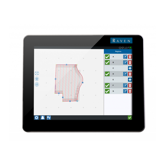
PLANNING 1. Select Operation Plans and the Add button in the upper, right corner. The Create Operation Plan window will open. 2. Enter a Name for the plan. 3. Enter a Swath Width that matches the implement width. NOTE: If using tram lines, enter the width of the planter. 4. - Page 32 PLAN OVERVIEW The plan overview screen displays the full plan. Each plan consists of field regions, lines, and offsets specific to that field. From this page, the user can add, edit, or remove regions. Any changes to the regions will be reflected in the plan overview screen.
- Page 33 TABLE 4. Region Settings Descriptions Setting Description Option This typically will only be used for areas not assigned as a Apply headland region. Enabling this option will apply the tramline Tramlines sequence to the selected baseline. Assign extra space between the main or center field region Extra Zone and the headlands.
-
Page 34: Run Screen Overview
14. Apply the Region Settings to all the desired baselines. NOTE: The region settings will default to the most recent Region Setting Configuration. As a rule, apply all the same types of offsets in order to minimize reconfiguration. 15. When starting a job, select the desired operation plan. 16. - Page 35 TABLE 5. Side Bar Icons Icon Name Description Indicates that the currently selected line is an AB Contour AB Contour. AB Heading Allows the user to enter a GPS heading. AB Load Load an AB guidance line. Indicates the current line is a straight AB AB Straight guidance line.
-
Page 36: Widgets
WIDGETS CRX offers additional tools, in the form of widgets, that may be placed on the run screen. Refer to Table 6 on page 34 for a brief overview of the widgets available for use during in-field operations. TABLE 6. CRX Widgets Widget Name Function... - Page 37 Widget Name Function Add the SmarTrax widget to easily view SmarTrax Status SmarTrax status or access SmarTrax Settings. Steering Status Steering is engaged. Implement Disk Display actual position of the discs/wheels. Angle Implement Display actual position of the side-shift Side- Shift cylinder.
-
Page 38: Widget Options
WIDGET OPTIONS Several widgets offer additional settings or options accessible on the run screen directly through the widget. Touch and hold a widget to display a settings prompt for the specific widget. Folded Corner SWITCHBOX OPERATION The switchbox widget allows the user to enable or disable sections or groups of sections while in the CRX run screen. -
Page 39: Scout Objects
FIGURE 18. Switchbox Configuration 4. Enter the number of switches. This number can be no greater than the total number of sections. If the number of switches is less than the number of sections, the sections are assigned to the switches proportionally. Any remaining switches are assigned from the center out. -
Page 40: Create A Field Boundary, Do Not Apply Zone, Or Application Zone
FIGURE 19. Create New Scout Feature 4. Select the desired recording point for the flag. It can be either centered with the implement, or on either side of the implement. 5. Select Create Flag CREATE A FIELD BOUNDARY, DO NOT APPLY ZONE, OR APPLICATION ZONE Field boundaries indicate the edges of a field. - Page 41 FIGURE 20. Create Line Left Center Right Enable Override Offset Offset from Center Automatic End Field Boundary Recording 5. Press Start Recording. 6. Drive the desired path/boundary. 7. When complete, select Scout Object 8. Select either Pause recording or End Recording NOTE: Enable the Close automatically option to allow CRX to automatically close the field boundary when the position nears the spot where the...
-
Page 42: Create Guidance Lines
CREATE GUIDANCE LINES 1. Select the guidance line icon. NOTE: The guidance line icon is the lowest icon on the right side of the screen and will be displayed as one of the available guidance line options. 2. Select the desired guidance line type. TABLE 7. - Page 43 FIGURE 21. AB Guidance Line Recording Starting Point End Point Flashing Light 4. When done recording, press the next point (in this case it will be B). 5. Select Accept to complete the line. 6. Select the guidance line icon along the right side of the screen. 7.
-
Page 44: Adjust Section Control
2. Press in the cell to the right of the desired setting. 3. Enter the desired setting. NOTE: If using a Raven AccuBoom node, select the Use AccuBoom check box and the AccuBoom node will control the sections for the implement selected in the drop-down list. -
Page 45: Adjust Rate Control Settings
4. Press Accept ADJUST RATE CONTROL SETTINGS 1. On the CRX Settings page, select Rate Control 2. Select the desired implement from the drop-down. 3. Select the cell next to the Prescription Map Look Ahead. 4. Enter the desired look ahead distance (in seconds). 5. -
Page 46: Localization
LOCALIZATION The Localization page provides options to adjust the language, time zone, and measurement units. To access Localization settings: 1. Press Localization on the CRX Settings screen. The Localization window will open. 2. Select the desired language from the Language drop down. 3. -
Page 47: Gps
NOTE: If Implement Steering is available, verify the Implement Steering GPS in addition to the machine’s GPS. 1. Press GPS on the CRX Settings screen. 2. Press the DIFF tab to view and select GPS Differential Setup information such as available differential Type and PRN. 3. -
Page 48: Remote Support
5. After viewing and editing the GPS information, Press Accept REMOTE SUPPORT Remote support allows a Raven service specialist to remotely view and control the CRX system. Remote support must be enabled by the user to allow a service specialist to help troubleshoot or access information. To enable remote support: NOTE: Remote support on CRX can only be performed via Slingshot. -
Page 49: Master Switch Configuration
MASTER SWITCH CONFIGURATION 1. Press Master Switch on the CRX Settings screen. The Master Switch Control Configuration window will open. 2. If desired, select the Require All On checkbox. This requires all selected inputs to be On for the Master to be on. Otherwise only one selected input needs to be on. 3. -
Page 50: Lightbar
LIGHTBAR NOTE: Lightbar configuration will only be available on CR12 if an external lightbar is detected. 1. To access the Lightbar Configuration settings, press Lightbar . The Lightbar Configuration window will open. 2. The default setting for the lightbar is that it is enabled. To disable the light-bar, deselect the Enable checkbox. -
Page 51: Wi-Fi Configuration
WI-FI CONFIGURATION To configure Wi-Fi settings and create a priority connection list: 1. Select the Networking button from the CRX Settings page. 2. Select the client and access point tabs. A list of available Wi-Fi connections will appear. FIGURE 24. Wi-Fi Connections 3. -
Page 52: Manual Network Creation
MANUAL NETWORK CREATION 1. Press Configure Networks at the bottom of the Network Settings screen. 2. Enter a name for the network in the SSID field. 3. Select the desired security level. If a secured network is selected, enter the desired Password. -
Page 53: Using The Power Button
USING THE POWER BUTTON 1. Press the power button until the Power Button Pressed prompt is displayed. 2. Select Screen Capture. 3. To move files from the CRX to a USB stick, perform the steps in “Exporting Screen shots” on page 51. EXPORTING SCREEN SHOTS 1. -
Page 54: File Manager
FILE MANAGER The file manager allows the user to sort and move files (if desired). If the file is currently located on a USB stick, connect to the USB port on the back of the CRX. FILE TYPES The table below shows available file types on the CRX. For a comprehensive list of file types, their extension type, and where they are typically located when saved to a USB stick, refer to Table 9 on page 66. -
Page 55: Copy A File
COPY A FILE 1. Press File Manager on the CRX Settings page. The File Management window will open. 2. Select either USB (if connected to the CRX) or Local (on CRX) from the source drop-down. 3. Select the checkbox for desired file(s) or All Files checkbox to select all of the files on the CRX or sort files by GFF. -
Page 56: Import Maps, Guidance Lines, And Feature Unlocks
IMPORT MAPS, GUIDANCE LINES, AND FEATURE UNLOCKS After downloading the desired file to a USB and inserting the USB into the CRX: 1. Press File Manager on the CRX Settings page. The File Management window will open. 2. Select USB from the left-most drop-down. FIGURE 26. - Page 57 FIGURE 28. File Management GFF Select 5. Press Copy Files . The files will copy to the CRX. 6. To verify unlocks have transferred successfully, navigate to the Features tab in the System Update field. The downloaded unlocks should now display with an open lock icon beside the feature.
-
Page 58: Load A Prescription Map
LOAD A PRESCRIPTION MAP 1. Place the prescription map file (this will be a .dbf, .shp, .shx file) on a USB drive. Do not create subfiles for the prescription maps. 2. Insert the USB drive into the CRX. 3. Select File Manager on the settings page. - Page 59 8. Press Accept to continue copying the file or press Cancel to select a different file. A Please Wait prompt will open while the files are being transferred. 9. Start a job. On the Coverage to Implement Assignment screen select Edit beside the desired prescription map.
-
Page 60: Eject The Usb
14. Press Next to begin the job. The prescription map will be visible on the run screen. FIGURE 34. Run Screen Prescription Map Prescription EJECT THE USB If a USB stick was installed, press Eject USB button to properly save the information on the USB stick so it can be removed. -
Page 61: Software And Hardware Updates
SOFTWARE AND HARDWARE UPDATES SOFTWARE To check for CRX software updates via Slingshot: 1. Press Software Update on the CRX Settings page. The Update page will open. 2. If there is an update available via Slingshot it will be listed under the Slingshot Link column. -
Page 62: Downloading A Crx Update To Usb
• Operation Planning: Operation planning allows the creation of headlands, offsets, and guidance lines within an existing boundary. The operation plan can then be selected jobs for various implements. 5. If desired, press the About tab to view information about the CRX including the software version, when the software version was installed, Run Hours, and Total Run Hours. -
Page 63: Iso Node And Gps Updates
ISO NODE AND GPS UPDATES To check for ISO Node or GPS updates via Slingshot: 1. Press Software Update on the CRX Settings page. The Update page will open. 2. Select the Hardware tab. 3. If there is an update available via Slingshot it will be listed under on the Hardware Update page. -
Page 64: Smartrax System Information
7. If desired, press the About tab to view information about the CRX including the software version, when the software version was installed, Run Hours, and Total Run Hours. If desired, press Erase Data to reset the system and erase all data stored on the CRX. This includes all implements, Grower/Farm/Field data, and settings on the CRX. -
Page 65: Temporary Unlock
The temporary unlock timer will continue until the unlock expires. Once the temporary unlock expires, the feature will be available using the activation package. Contact a local Raven dealer for additional assistance with temporary unlocks or feature activation. -
Page 66: Permanent Unlock
Job Code, Identification Number, and the countdown clock for the subscription. FIGURE 40. Subscription Status PERMANENT UNLOCK Permanent unlocks must be purchased through a Raven dealer. After purchasing the unlocks the files are loaded to the CRX with a USB drive. To install a permanent unlock on the CRX: 1. -
Page 67: System Shutdown
SYSTEM SHUTDOWN 1. To turn off the system, press the System Shutdown button or press the power button on the back of the CRX. A Confirm Shutdown window will open. 2. Press Accept to turn off the system or Cancel to return to the CRX Settings screen. -
Page 68: Usb Import And Export File Types
Line GuidanceLines/*.ab /Raven/GFF/{Grower Field Name}/ {Farm Name}/ {Field Name}*.fld • GFF/{Grower Name}/ {Farm Name}/{Field Name}/*.shp (.shx, .dbf, .prj) Field Extent • /Raven/GFF/{Grower Name}/ {Farm Name}/ {Field Name}/*.shp (.shx, .dbf, .prj) Firmware • /Raven/500S/ • *.bin 500S • /Raven/600S/ *.hex Firmware •... - Page 69 Function Import Type Export Type Typical USB Location • /Raven/CAN/ *.hex • Raven/CAN/ Firmware *.rvu • /*.hex • /*.rvu • /*.jdp • /*.jdp • GFF/{Grower Name}/ {Farm Name}/{Field Name}/*shp (.shx, .dbf, Multi .prj) Boundary • Raven/GFF/{Grower Name}/ {Farm Name}/ *.shp (.shx, .dbf, .prj) •...
- Page 70 HOW CAN I GET SERVICE? Bring the defective part and proof of purchase to your Raven dealer. If the dealer approves the warranty claim, the dealer will process the claim and send it to Raven Industries for final approval. The freight cost to Raven Industries will be the customer’s responsibility.
- Page 71 WHAT IS NOT COVERED BY THIS WARRANTY? Raven Industries will not assume any expense or liability for repairs made outside our facilities without written consent. Raven Industries is not responsible for damage to any associated equipment or products and will not be liable for loss of profit, labor, or other damages. The...
- Page 72 24 months from the date of retail sale. In no case will the Extended Warranty period exceed 36 months from the date the product was issued by Raven Industries Applied Technology division. This Extended Warranty coverage applies only to the original owner and is non-transferable.
- Page 73 HOW CAN I GET SERVICE? Bring the defective part and proof of purchase to your Raven dealer. If the dealer approves the warranty claim, the dealer will process the claim and send it to Raven Industries for final approval. The freight cost to Raven Industries will be the customer’s responsibility.
Need help?
Do you have a question about the CR Series and is the answer not in the manual?
Questions and answers