
Related Manuals for Delta AG9064


Summary of Contents for Delta AG9064
- Page 1 Delta Networking – Agema Family AG9064 Spine Switch Installation Guide agema.deltaww.com...
- Page 2 All trademarks and logos mentioned in this guide are the properties of their respective holders. Copyright © Delta Electronics, Inc. All rights reserved. Regulatory and Safety Information This product has been tested in accordance to, and complies with the following safety standards and electromagnetic compatibility (EMC) inspection standards.
-
Page 3: Lithium Battery Caution
Warning: Fiber Optic Port Safety When using a fiber optic port, never look at the transmit laser while it is powered on. Also, never look directly at the fiber TX port and fiber cable ends when they are powered on. Avertissement : Consignes de sécurité... -
Page 4: Table Of Contents
Chapter 4: Making the Network Connections ----------------------------------- 18 4.1 Twisted-pair Connections --------------------------------------------------------------18 4.2 Fiber Optic Connections ---------------------------------------------------------------19 4.3 Ethernet Cabling -------------------------------------------------------------------------20 Appendix 1 : Technical Specifications --------------------------------------------- 21 Appendix 2 : Warranty ------------------------------------------------------------------- 22 Limited and Support Warranty -------------------------------------------------------------22 Technical Support -----------------------------------------------------------------------------22 AG9064 Spine Switch... -
Page 5: Chapter 1: Introduction
Chapter 1: Introduction Overview The AG9064 is a high performance, high density, 2RU, next generation Spine switch with target application for Enterprise Campus Backbone, Data Center and Service Provider deployment. It has sixty-four 100GbE QSFP28 ports which provides 6.4Tbps bandwidth configurable to multi-rate 40/100GbE at desired fabric speed. -
Page 6: Features
Features The following lists the key main features of AG9064 switch: • 64 x 100GbE QSFP28 ports, support splitter cable • 1 x OOB BMC management port • 1 x Console port (RJ-45 type) • 1 x USB port • Hot plugging redundant power supply support •... -
Page 7: Chapter 2: Appearance And Mechanism
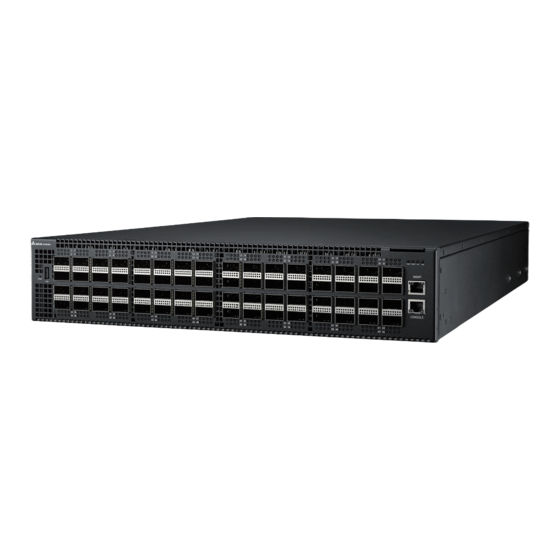
Chapter 2: Appearance and Mechanism Product Overview 2.1.1 Front View USB port x 1 Management port x 1 RJ-45 Console port x 1 QSFP28 ports x 64 (Figure 2-1: Front View) 2.1.2 Rear View 4 Fan tray slots Redundant PSU x 2 (Figure 2-2: Rear View) NOTE: The switch supports up to two PSUs. -
Page 8: Led Identification
• 100G QSFP28 Solid White – 50G Operation • slots Solid Amber – 40G Operation • Four LEDs / Solid Blue – 25G Operation • port Solid Purple – 10G Operation • Off – No Link • AG9064 Spine Switch... - Page 9 Chapter 2 • Appearance and Mechanism Description LED 2 (Solid Lighting – Linkup; Blinking – Activity) Solid Blue – 25G Operation • Solid Purple – 10G Operation • Off – No link • LED3 (Solid Lighting – Linkup; Blinking – Activity) 100G QSFP28 Solid White –...
- Page 10 Fan LED (Figure 2-4: Rear LED Identification) Description Green – FAN operating normally • Fan LED Red – FAN failed • Off – Power failure or no power • PSU LED Solid Green – Power is ok • AG9064 Spine Switch...
-
Page 11: System Requirements
Chapter 2 • Appearance and Mechanism System Requirements Component Requirement System requirements Switch fabric capacity Non-blocking full wire speed on all packet sizes Forwarding architecture Store and forward or cut-through • 148,000,000 pps (100GbE) Port packet forwarding rate • 59,520,000 pps (40GbE) (at 64 Bytes) •... -
Page 12: Data Center Deployment
100G downlink 100G downlink 100G downlink 100G downlink (Figure 2-5: Converged Ethernet Data Center Deployment) Controller Super Spine AG9064 100GbE Spine 100GbE Spine AG9064, AG9032 v1, Spine Spine AG9032 v2, AG8032 AG5648V1, AG7648, Leaf Leaf AG7648C Pod 1 Pod N... -
Page 13: Power Supply Modules
Chapter 2 • Appearance and Mechanism Power Supply Modules The power supply modules are hot-swappable power supply units (PSUs) for the switch. You can install up to two PSUs. The PSUs operate in a load-sharing mode and provides 1+1 redundancy. (Figure 2-7: Power Supply Unit) NOTE: 1+1 redundancy is a system where a switch power supply is backed up by... -
Page 14: Fan Tray Module
The fan tray module is part of the switch air cooling system that provides cooling for the switch. You must install the fan tray module in the switch that matches the airflow direction of the installed power supply unit. (Figure 2-8: Fan Tray Module) AG9064 Spine Switch... -
Page 15: Chapter 3: Installation
Chapter 3: Installation Mounting This switch can be mounted in a standard 19-inch equipment rack or on a horizontal surface. Mounting instructions for each type of site follow. 3.1.1 Rack Mounting Prior rack mounting the switch, pay particular attention to the following factors: Mechanical Loading: Do not place any equipment on top of a rack-mounted unit. - Page 16 (Figure 3-4: Securing the Rear Mounting Brackets) 5. If installing a single switch only, go to “Connecting to a Power Source”. 6. If installing multiple switches, mount them in the rack, one below the other, in any order. AG9064 Spine Switch...
-
Page 17: Horizontal Surface Mounting
Chapter 3 • Installation 3.1.2 Horizontal Surface Mounting The switch includes four pre-installed rubber feet for horizontal surface mounting. To mount devices on a horizontal surface, follow these steps: 1. Attach the four adhesive feet to the bottom of the first switch. (Figure 3-5: Attaching the Adhesive Feet) 2. -
Page 18: Installing An Optional Qsfp/Qsfp28 Transceiver
QSFP/QSFP28 transceivers are not provided in the switch package. • QSFP28 Ports to SFP28 Ports: The AG9064 also supports splitting a • 100G QSFP28 port into 25G ports via the breakout cables. Do consult your software provider for port mode change and configuration. -
Page 19: Connecting To The Console Port
Chapter 3 • Installation Connecting to the Console Port This port is used to connect a console device to the switch through a nullmodem serial cable. The console device can be a PC or workstation running a VT-100 terminal emulator, or a VT- 100 terminal. -
Page 20: Installing A Dc Power Supply
PWR1 LED is on. If not, check that the power cable is correctly plugged in. 4. Repeat steps 1 and 2 when a second PSU module is installed. Two installed PSU modules operate in a load-sharing mode and provide 1+1 redundancy. AG9064 Spine Switch... - Page 21 Chapter 3 • Installation b. Adapter connector for DC source connection 1. Attach the connector directly into the DC socket of a PSU located at the back of the switch. -48V_RTN (+DC) -48V(-DC) (Figure 3-10: Assembling a DC Connector and Power Wires) 2.
-
Page 22: Chapter 4: Making The Network Connections
Chapter 4: Making the Network Connections The AG9064 switch is designed to provide high-speed, lossless Ethernet connections between server racks through its 100G QSFP ports. This chapter describes how to make network connections to the switch. Twisted-pair Connections The switch’s Management port connection requires an unshielded twisted-pair (UTP) cable with RJ-45 connectors at both ends. -
Page 23: Fiber Optic Connections
Chapter 4 • Making the Network Connections Fiber Optic Connections Optional 100G QSFP28 transceivers can be used for fiber connections from the switch to other network devices in the data center. A QSFP28 transceiver may also be used for long distance connections to devices at another site. -
Page 24: Ethernet Cabling
Protection from radio frequency interference emissions • Electrical surge suppression • Separation of electrical wires (switch related or other) and electromagnetic fields from • data based network wiring Safe connections with no damaged cables, connectors or shields • AG9064 Spine Switch... -
Page 25: Appendix 1 : Technical Specifications
Appendix 1 : Technical Specifications Item Description Key components Switch controller BCM56970 x 1 I210-AT x 1 (for Management port) Intel Broadwell D1527 Quad Core Flash Rom 32MB SPI Flash System Memory 16GB DDR4-SO-DIMM * 2 mSATA Device 128GB SSD M.2 SSD AST2520, 8GB DDR3, 32MB Flash ST33HTP Network Protocol and Standards Compatibility... -
Page 26: Appendix 2 : Warranty
During the warranty period, products for which proper claims are made will, at Delta’s option, be repaired or replaced at Delta’s expense. Customers may contact Delta’s technical support for warranty services, which may be provided either through Resellers or by Delta directly. -
Page 27: Return Policy
Any product returned to Delta or Resellers without prior Return Material Authorization (RMA) from Delta will be considered an unauthorized return, and you will not receive any repair or replacement for the product and Delta will not ship the product back to you. The authorization will be provided through the e-mail: AgemaTechSupport@deltaww.com.