
Related Manuals for Delta AG9032


Summary of Contents for Delta AG9032
- Page 1 Delta Networking – Agema Family AG9032 v1 Spine and Leaf Switch Installation Guide...
- Page 2 All trademarks and logos mentioned in this guide are the properties of their respective holders. Copyright © Delta Products Corporation. All rights reserved. Regulatory and Safety Information This product has been tested in accordance to, and complies with the following safety standards and electromagnetic compatibility (EMC) inspection standards.
-
Page 3: Table Of Contents
Table of Contents Table of Contents Chapter 1: Introduction -------------------------------------------------------------------1 1.1 Overview ------------------------------------------------------------------------------------ 1 1.2 Package Content ------------------------------------------------------------------------- 1 1.3 Features------------------------------------------------------------------------------------- 2 Chapter 2: Appearance and Mechanism --------------------------------------------3 2.1 Product Overview ------------------------------------------------------------------------- 3 2.2 LED Identification ------------------------------------------------------------------------- 4 2.3 System Requirements ------------------------------------------------------------------- 6 2.4 Data Center Deployment --------------------------------------------------------------- 7 2.5 Power Supply Modules ------------------------------------------------------------------ 7 2.6 Fan Tray Module -------------------------------------------------------------------------- 8... -
Page 4: Chapter 1: Introduction
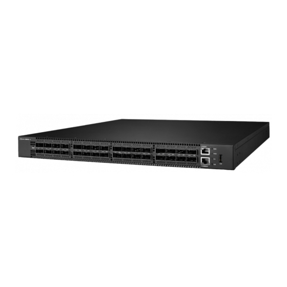
Chapter 1: Introduction Overview The AG9032 v1 is a high performance, high density next generation switch with target application for Data Center Networks. It has Thirty-Two 100GbE QSFP28 ports which support 100GE Applications. In addition to the rich bandwidth, the AG9032 v1 provides... -
Page 5: Features
Chapter 1 • Introduction Features The following lists the key main features of the AG9032 v1 switch: • 32 x 100GbE QSFP28 ports • 1 x OOB Management • 1 x Console port (RJ-45 type) • 1 x USB port •... -
Page 6: Chapter 2: Appearance And Mechanism
(Figure 2-2: Rear View) NOTE: The switch supports up to two PSUs. However, it is shipped with one power supply pre-installed in the rear panel of the switch. You can purchase an additional PSU if necessary. AG9032 v1 Spine and Leaf Switch... -
Page 7: Led Identification
Chapter 2 • Appearance and Mechanism LED Identification This section provides an overview of the front and rear LEDs. 2.2.1 Front LEDs Upper QSFP28 Port LED Power 1 LED Power 2 LED System LED Fan LED Lower QSFP28 Port LED (Figure 2-3: Front LED Identification) Description Off –... - Page 8 (Figure 2-4: Rear LED Identification) Description Green – FAN operating normally • Fan LED Red – FAN failed • Off – Power failure or no power • PSU LED Solid Green – Power is ok • AG9032 v1 Spine and Leaf Switch...
-
Page 9: System Requirements
Chapter 2 • Appearance and Mechanism System Requirements Component Requirement System requirements Switch fabric capacity Non-blocking full wire speed on all packet sizes Forwarding architecture Store and forward or cut-through • 14800000 pps (100Gb) Port packet forwarding rate • 595,200,000 pps (40GbE) (at 64 Bytes) •... -
Page 10: Data Center Deployment
Risk of explosion if battery is replaced by an incorrect type. Dispose of used batteries according to the instructions. • Remove the power cable from the module prior to removing the module itself. Power cable must not be connected prior to insertion in the chassis or equivalent. AG9032 v1 Spine and Leaf Switch... -
Page 11: Fan Tray Module
Chapter 2 • Appearance and Mechanism Fan Tray Module The fan tray module is part of the switch air cooling system that provides cooling for the switch. You must install the fan tray module in the switch that matches the airflow direction of the installed power supply unit. -
Page 12: Chapter 3: Installation
2. Mount the device in the rack, using four 12-24 rack-mounting screws. NOTE: Rack screws and clip nuts are not supplied in the rack-mounting kit. CAUTION: Due to the switch’s weight, it should be installed by at least two people. AG9032 v1 Spine and Leaf Switch... -
Page 13: Horizontal Surface Mounting
Chapter 3 • Installation (Figure 3-2: Installing the Switch in a Rack) 3. If installing a single switch only, go to “ Connecting to a Power Source ”. 4. If installing multiple switches, mount them in the rack, one below the other, in any order. 3.1.2 Horizontal Surface Mounting The switch includes four pre-installed rubber feet for horizontal surface mounting. -
Page 14: Installing An Optional Qsfp/Qsfp28 Transceiver
• QSFP/QSFP28 transceivers are not provided in the switch package. • QSFP28 Ports to SFP28 Ports: The AG9032 v1 also supports splitting a 100G QSFP28 port into 25G ports via the breakout cables. Do consult your software provider for port mode change and configuration. -
Page 15: Connecting To The Console Port
Chapter 3 • Installation Connecting to the Console Port This port is used to connect a console device to the switch through a nullmodem serial cable. The console device can be a PC or workstation running a VT-100 terminal emulator, or a VT- 100 terminal. -
Page 16: Installing A Dc Power Supply
PWR1 LED is on. If not, check that the power cable is correctly plugged in. 4. Repeat steps 1 and 2 when a second PSU module is installed. Two installed PSU modules operate in a load-sharing mode and provide 1+1 redundancy. AG9032 v1 Spine and Leaf Switch... - Page 17 Chapter 3 • Installation b. Adapter connector for DC source connection 1. Attach the connector directly into the DC socket of a PSU located at the back of the switch. -48V_RTN (+DC) -48V(-DC) (Figure 3-8: Assembling a DC Connector and Power Wires) 2.
-
Page 18: Chapter 4: Making The Network Connections
Chapter 4: Making the Network Connections The AG9032 v1 switch is designed to provide high-speed, lossless Ethernet connections between server racks through its 100G QSFP ports. This chapter describes how to make network connections to the switch. Twisted-pair Connections The switch’s Management port connection requires an unshielded twisted-pair (UTP) cable with RJ-45 connectors at both ends. -
Page 19: Fiber Optic Connections
Chapter 4 • Making the Network Connections Fiber Optic Connections Optional 100G QSFP28 transceivers can be used for fiber connections from the switch to other network devices in the data center. A QSFP28 transceiver may also be used for long distance connections to devices at another site. -
Page 20: Appendix 1 : Technical Specifications
438.5 x 460 x 43.5 mm (17.26 x 18.11 x 1.71 inches) Weight 9.1 kg (20.06 lbs) Environmental Specifications Operating temperature 0 to 40°C Storage temperature -20 to 70°C Operating humidity 10 to 90% RH Storage humidity 5 to 95% RH AG9032 v1 Spine and Leaf Switch... -
Page 21: Appendix 2 : Warranty
During the warranty period, products for which proper claims are made will, at Delta’s option, be repaired or replaced at Delta’s expense. Customers may contact Delta’s technical support for warranty services, which may be provided either through Resellers or by Delta directly. -
Page 22: Return Policy
Any product returned to Delta or Resellers without prior Return Material Authorization (RMA) from Delta will be considered an unauthorized return, and you will not receive any repair or replacement for the product and Delta will not ship the product back to you. The authorization will be provided through the e-mail: AgemaTechSupport@deltaww.com.
Need help?
Do you have a question about the AG9032 and is the answer not in the manual?
Questions and answers