
Subscribe to Our Youtube Channel
Related Manuals for Delta InfraSuite STS 16A


Summary of Contents for Delta InfraSuite STS 16A
- Page 1 The power behind competitiveness Delta InfraSuite Power Management Static Transfer Switch User Manual www.deltapowersolutions.com...
- Page 2 Failure to heed these instructions and warnings will void the warranty. Copyright © 2016 by Delta Electronics Inc. All Rights Reserved. All rights of this User Manual (“Manual”), including but not limited to the contents, information, and figures are solely owned and reserved by Delta Electronics Inc.
-
Page 3: Table Of Contents
Table of Contents Table of Contents Chapter 1 : Important Safety Instructions --------------------------- 1 Important Safety Notes ---------------------------------------- 1 Electrical Warnings ---------------------------------------------- 1 Standard Compliance ------------------------------------------ 2 Chapter 2 : Product Introduction --------------------------------------- 3 Product Description --------------------------------------------- 3 Features ----------------------------------------------------------- 3 Chapter 3 : Package and Storage -------------------------------------- 4 Package Contents ----------------------------------------------- 4 Storage ------------------------------------------------------------- 4... - Page 4 STS Command Settings --------------------------------------25 Key Generation for SSH --------------------------------------29 Chapter 8 : Troubleshooting --------------------------------------------31 Appendix 1 : Specifications ---------------------------------------------32 Appendix 2 : Warranty ----------------------------------------------------33 InfraSuite Power Management...
-
Page 5: Chapter 1 : Important Safety Instructions
Chapter 1 Important Safety Instructions Chapter 1 : Important Safety Instructions 1.1 Important Safety Notes Only qualified personnel can service this equipment. Follow the following precautions when working on this unit. 1. Remove watches, rings, or other metal objects. 2. Use tools with insulated handles. 3. -
Page 6: Standard Compliance
1.3 Standard Compliance Safety UL (US) (UL 60950) CE (EU) (IEC 60950) CISPR 22 Class A and FCC Class A IEC 61000-4-2 IEC 61000-4-3 IEC 61000-4-4 IEC 61000-4-5 IEC 61000-4-6 IEC 61000-4-8 IEC 61000-4-11 IPv6 Certification IPv6 Ready Logo Phase 2 (Core for Host, Logo ID 02-C-000624) InfraSuite Power Management... -
Page 7: Chapter 2 : Product Introduction
Chapter 2 Product Introduction Chapter 2 : Product Introduction 2.1 Product Description The STS is designed to guarantee the uninterrupted operation of sensitive equip- ment. It is powered by two independent power sources and automatically makes a rapid switch from one source to the other when the original power supplying to its connected load fails. -
Page 8: Chapter 3 : Package And Storage
Chapter 3 : Package and Storage 3.1 Package Contents × × × × × × STS package contains the following items. Item Quantity STS module 1 PC Extension Ethernet cable 1 PC Bracket Ear 2 PCS Rack nut 4 PCS Rack screw 4 PCS Bracket screw... -
Page 9: Chapter 4 : Installation
Chapter 4 Installation Chapter 4 : Installation Front Installation Use the eight bracket screws (provided) to attach the two bracket ears (provided) to the lateral mounting holes located in the front of the STS. Please see Figure 4-1. Bracket Ear x 1 Bracket Screw X 4 Bracket Ear x 1 Bracket Screw X 4... - Page 10 Rear Installation Use the eight bracket screws (provided) to attach the two bracket ears (provided) to the lateral mounting holes located at the rear of the STS. Please see Figure 4-3. Bracket Ear x 1 Bracket Screw X 4 Bracket Ear x 1 Bracket Screw X 4 (Figure 4-3) Use the four rack screws (provided) and four rack nuts (provided) to fix the...
-
Page 11: Chapter 5 : Wiring
Chapter 5 Wiring Chapter 5 : Wiring (Figure 5-1: Front view) Use input power cables (not provided) to connect the STS and two UPSs (UPS1 (S1) is the preferred source). Use output power cables (not provided) to connect the STS and loads. NOTE : To avoid the loose input/ output power cables, please use the provided wire mounts and cables ties to fix the input/ output power cables to the... - Page 12 A. Firmly insert the power cables into the outlets/ sockets ( ) and insert the ), Please refer to Figure 5-2. cable ties into the wire mounts ( Cable Tie Cable Tie Wire Mount Wire Mount (Figure 5-2) B. Firmly insert the wire mounts into the power cables ( ) and insert each cable tie’s peak into the according slot ( ).
- Page 13 Chapter 5 Wiring ). Please refer to Figure 5-4. C. Clip each wire mount firmly ( Wire Mount Wire Mount (Figure 5-4) Connect to the Ethernet Network. There are two methods. 1. Method 1 (Front Application): Use the provided extension Ethernet cable to connect the rear panel’s NETWORK port and the rear panel’s TRANSFER PORT;...
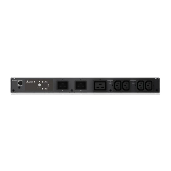
- Page 14 2. Method 2 (Rear Application): Use a user-supplied Ethernet cable to connect to the rear panel’s NETWORK port; please see Figure 5-6. NET WO RK LOC AL RES ET TRA NSF ER POR T (Figure 5-6: Rear view) InfraSuite Power Management...
-
Page 15: Chapter 6 : Operation
Chapter 6 Operation Chapter 6 : Operation 6.1 Front Panel NETWORK S1-ON LOAD LOAD TEST S2-ON S1-ON TEST S2-ON Item Description S1 LED Green. The LED indicates the condition of input source 1. If the input source 1 is within the acceptable range, the LED will light up as green. - Page 16 Item Description Green. The LED indicates the output condition (voltage is > 60Vac). If there is output, the LED will light up as green. If not, the LED will be off. Test Use this button to test the STS. Press the button, the STS will Button transfer to the 2 source for 1 minute and then transfer back to...
-
Page 17: Rear Panel
Chapter 6 Operation Item Description Fault Environmental Fault Error Code Meaning Output overload Over temperature (due to detection of ambient temperature) Output temperature warning (due to detection of S1 heat-sink temperature) Over temperature warning (due to detection of S2 heat-sink temperature) 6.2 Rear Panel NETWORK LOCAL... - Page 18 Item Description NETWORK Connects to the Ethernet Network. Port LOCAL Connects to a workstation with an RJ45 to DB9 cable to Port configure the system. RESET Resets InsightPower SNMP IPv6 for STS (hereafter referred Button to as SNMP IPv6). This does not affect the operation of the STS.
- Page 19 Chapter 6 Operation Item Description Set up operation mode. Please refer to the following table. Switches DIP Switch 1 DIP Switch 2 Operation Description Switch 1 Switch 2 Mode The built-in SNMP IPv6 provides the STS’s Normal status information and Mode parameters through a network system.
-
Page 20: Operation
6.3 Operation 2 poles circuit breaker (L1) (N1) (Source 1) To the sensitive equipment 2 poles circuit breaker (L2) (N2) (Source 2) After power connection, the STS will automatically perform power-on self-test. After the test, the STS will start supplying power to its connected equipment. You can also press the ‘Test Button’... -
Page 21: Chapter 7 : Insightpower Snmp Ipv6 For Sts
Allows remote management of the STS from any workstation through Internet or Intranet. Remote STS monitoring via SNMP & HTTP Allows remote monitoring of the STS using SNMP NMS, Delta MIB (Management Information Base) or a Web Browser. STS and system configuration from any client (password protected) Sets the STS and system parameters through a Web Browser. -
Page 22: Top View And Front View Of Snmp Ipv6
- RADIUS (Remote Authentication Dial In User Service) login and local authentication - Remote event log management through syslog - IPv6 Ready Logo certified (ID 02-C-000624) DEFAULT SETTING User Name: admin Password: password DHCP Client: Enable IPv4 Address: 192.168.1.100 7.3 Top View and Front View of SNMP IPv6 Top View Network Port LED Indicators... -
Page 23: Console Management
Chapter 7 InsightPower SNMP IPv6 for STS 7.4 Console Management You can manage the SNMP IPv6 through the LOCAL port. Please use an RJ45 to DB9 cable to connect the SNMP IPv6’s LOCAL port and your workstation’s COM port. Make sure both of the DIP switches are set to the OFF position (normal mode). The baud-rate of the workstation’s COM setting should be 2400 bps. - Page 24 TCP/ IP Setting +========================+ TCP/IP Setting +========================+ [1].IPv4 Address: 192.168.1.100 [2].IPv4 Subnet Mask: 255.255.255.0 [3].IPv4 Gateway IP: 192.168.1.254 [4].IPv4 DNS or WINS IP:192.168.1.254 [5].DHCPv4 Client: Enable [6].IPv6 Address: [7].IPv6 Prefix Length: 0 [8].IPv6 Gateway IP: fe80::226:Sbff:fecc:fdal [9].IPv6 DNS IP: [a].DHCPv6: Disable [b].Host Name(NetBIOS): INSIGHTPOWER [c].System Contact:...
- Page 25 Chapter 7 InsightPower SNMP IPv6 for STS Time Server +========================+ Time Server +========================+ [1].Time Selection: SNTP [2].Time Zone: +0 hr [3].1st Time Server: [4].2nd Time Server: [5].Manual Date: 01/01/2000 (MM/DD/YYYY) [6].Manual Time: 00:00:00 (hh:mm:ss) [0].Back To Previous Menu Please Enter Your Choice => Soft Restart +========================+ Web Card Main Menu...
- Page 26 Device Communication You can enter the STS Command Mode below by selecting Device Communi- cation. STS> Vs1 216.8 STS> Vs2 217.9 STS> Iout STS> Vout 217.1 STS> Vbp2s 180.0 STS> Vbs2p 180.0 STS> Tdp2s 12.0 STS> Tds2p 12.0 STS> TempF STS>...
-
Page 27: Upgrade
Chapter 7 InsightPower SNMP IPv6 for STS 7.5 Upgrade Upgrade via Web You can upgrade the SNMP IPv6’s firmware or the STS’s firmware through the InsightPower SNMP IPv6 for STS Web (please see the following figure). The SNMP IPv6 will restart after finishing self-upgrade. If you upload the STS’s firmware to the Web, you can see the STS’s firmware upgrade progress from the Web. - Page 28 Upgrade via EzSetting You can also upgrade the SNMP IPv6’s firmware or the STS’s firmware by using EzSetting. 1. Click Discover. A list of SNMP devices is shown. Select a device from the Device List, and click Modify. 2. Enter Administrator account and password. InfraSuite Power Management...
-
Page 29: Sts Command Settings
Chapter 7 InsightPower SNMP IPv6 for STS 3. Click Upgrade. The upgrade dialog box pops up. Click Browse to select a valid firmware binary file. Verify the firmware version shown under File Information, and then click Upgrade Now to continue. 7.6 STS Command Settings Command Description... - Page 30 Command Description Parameter Response DevID Report the unit’s device <Device ID string> Prefer Report the preferred S1 or S2 source. Sens Report the sensitivity. hi or low Mode Report the operation Initialization mode. Diagnosis Safe Fault Vout Report the output voltage. Iout Report the output current.
- Page 31 Chapter 7 InsightPower SNMP IPv6 for STS Command Description Parameter Response Tdp2s Report the recover time of transfer from primary to secondary. Tds2p Report the recover time of transfer from secondary to primary. Mvs1 Report the max voltage of comparing cycles for primary AC blackout.
- Page 32 Command Description Parameter Response SetPrefer Set the preferred source. 1 or 2 Various kinds SetDevID Set the unit's device ID. <20 Various kinds characters> alphanumeric only SetVtp2s Set the primary to 165.0 ~ 175.0 Various kinds secondary trip voltage. SetVts2p Set the secondary to 165.0 ~ 175.0 Various kinds primary trip voltage.
-
Page 33: Key Generation For Ssh
Chapter 7 InsightPower SNMP IPv6 for STS Command Description Parameter Response UpProcess Status of upgrade Idle / Run / Error progress. UpStep Stage of upgrade Init / File ID / Auth progress. / Addr / Erase / Program / Read UpPercentage Percentage of upgrade progress. - Page 34 For Windows (1) Please download and install PuTTY from http://www.putty.org. (2) Run puttygen.exe from the installed directory. (3) Select SSH-2 RSA from the Parameters area and click Key→ Generate key pair to generate an RSA key. (4) Select Conversions→ Export OpenSSH Key and assign a file name to the RSA key.
-
Page 35: Chapter 8 : Troubleshooting
Chapter 8 Troubleshooting Chapter 8 : Troubleshooting Problem Possible case Solution 1. Check the output (overload/ short- circuit). All LEDs on The power sources, the front S1 and S2, are both 2. Check both power sources, S1 and panel are off. absent. -
Page 36: Appendix 1 : Specifications
Appendix 1 : Specifications STS 16A Nominal Voltage 200/ 208/ 220/ 230/ 240V Operating Frequency 45Hz to 65HZ Nominal Current Input Connection C20 x 2 Output Connection C13 x 4 & C19 x 1 Physical Dimensions 440 x 385 x 43 mm (W x D x H) Weight 4.85 Kg... -
Page 37: Appendix 2 : Warranty
Appendix 2 Warranty Appendix 2 : Warranty Seller warrants this product, if used in accordance with all applicable instructions, to be free from original defects in material and workmanship within the warranty period. If the product has any failure problem within the warranty period, Seller will repair or replace the product at its sole discretion according to the failure situation. - Page 40 5013236701...
Need help?
Do you have a question about the InfraSuite STS 16A and is the answer not in the manual?
Questions and answers