
Related Manuals for Delta AGC7648A


Summary of Contents for Delta AGC7648A
- Page 1 Delta Networking – Agema Family AGC7648 Deep-Buffer Switch - AGC7648A - AGC7648S Installation Guide...
- Page 2 All trademarks and logos mentioned in this guide are the properties of their respective holders. Copyright © Delta Products Corporation. All rights reserved. Regulatory and Safety Information This product has been tested in accordance to, and complies with the following safety standards and electromagnetic compatibility (EMC) inspection standards.
-
Page 3: Table Of Contents
Table of Contents Table of Contents Chapter 1: Introduction -------------------------------------------------------------------1 1.1 Overview ------------------------------------------------------------------------------------ 1 1.2 Package Content -------------------------------------------------------------------------- 1 1.3 Features ------------------------------------------------------------------------------------- 2 Chapter 2: Appearance and Mechanism --------------------------------------------3 2.1 Product Overview ------------------------------------------------------------------------- 3 2.2 LED Identification ------------------------------------------------------------------------- 4 2.3 System Requirements ------------------------------------------------------------------- 6 2.4 Data Center Deployment ---------------------------------------------------------------- 7 2.5 Power Supply Modules ------------------------------------------------------------------ 8 2.6 Fan Tray Module -------------------------------------------------------------------------- 8... -
Page 4: Chapter 1: Introduction
Then, before beginning the installation, be sure you have all other necessary installation equipment. • AGC7648 series switch: AGC7648A or AGC7648S • 1 x AC power supply for AC version or 1 x DC power supply for DC version •... -
Page 5: Features
Chapter 1 • Introduction Features The following lists the main features of the AGC7648 switch: • 48 x 10GbE SFP+ ports • 6 x 100GbE QSFP28 ports • 1 x OOB Management • 1 x Console port (RJ-45 type) • 1 x USB port •... -
Page 6: Chapter 2: Appearance And Mechanism
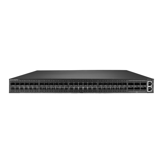
Chapter 2: Appearance and Mechanism Product Overview 2.1.1 Front View Management port x 1 QSFP28 port x 6 Console port x 1 SFP+ port x 48 (Figure 2-1: Front View) 2.1.2 Rear View 4 Fan tray slots USB port x 1 Reset x 1 Secondary PSU PSU x 1... -
Page 7: Led Identification
Chapter 2 • Appearance and Mechanism LED Identification This section provides an overview of the front and rear LEDs. 2.2.1 Front LEDs Upper QSFP28 Port LED Upper SFP+ Port LED Power LED System LED Fan LED Lower SFP+ Port LED Lower QSFP28 Port LED (Figure 2-3: Front LED Identification) Description... - Page 8 Description Link LED (Left) Off – No link • Solid Green – A valid 10Gbps link • Solid Yellow – A valid 1G link • 10G SFP+ slots Act LED (Right) Off – No link • Solid Green – A valid 10Gbps link •...
-
Page 9: System Requirements
Chapter 2 • Appearance and Mechanism 2.2.2 Rear LEDs Fan tray LED Power Supply LED (Figure 2-4: Rear LED Identification) Description Solid Green – Fan is operating normally • Fan tray LED Solid Red – Fan failure • Off – No power or power supply failed Power Supply •... -
Page 10: Data Center Deployment
Data Center Deployment The following figure illustrates the converaged Ethernet data center deployment. VNF/Services Control Plane Control Plane AG9032 v1 AG9032 v1 AG9032 v1 Leaf-Spine SDN enabled Central Office Fabric Fabric AGC7648 AGC7648 AGC7648 AGC7648 AGC7648 Commodity servers, switches and networks access (Figure 2-5: Carrier High Level Architecture) VPN/MPLS Internet... -
Page 11: Power Supply Modules
Chapter 2 • Appearance and Mechanism Power Supply Modules The power supply modules are hot-swappable power supply units (PSUs) for the switch. You can install up to two PSUs. The PSUs operate in a load-sharing mode and provides 1+1 redundancy. (Figure 2-7: Power Supply Unit) NOTE: 1+1 redundancy is a system where a switch power supply is backed up by... -
Page 12: Chapter 3: Installation
Chapter 3: Installation Mounting This switch can be mounted in a standard 19-inch equipment rack or on a horizontal surface. Mounting instructions for each type of site follow. 3.1.1 Rack Mounting Prior rack mounting the switch, pay particular attention to the following factors: •... -
Page 13: Horizontal Surface Mounting
Chapter 3 • Installation (Figure 3-2: Installing the Switch in a Rack) 3. If installing a single switch only, go to “ Connecting to a Power Source ”. 4. If installing multiple switches, mount them in the rack, one below the other, in any order. 3.1.2 Horizontal Surface Mounting The switch includes four pre-installed rubber feet for horizontal surface mounting. -
Page 14: Installing An Optional Sfp+/Qsfp/Qsfp28 Transceiver
Installing an Optional SFP+/QSFP/QSFP28 Transceiver The SFP+ slots support the following optional transceivers and cables: • 10GBASE-SR • 10GBASE AOC • 1GBase-SX • 10GBASE-LR • 10GBASE DAC • 1GBase-LX The QSFP28 slots support the following optional transceivers and cables: • 100G Base-SR4 •... -
Page 15: Connecting To The Console Port
Chapter 3 • Installation Connecting to the Console Port This port is used to connect a console device to the switch through a nullmodem serial cable. The console device can be a PC or workstation running a VT-100 terminal emulator, or a VT-100 terminal. -
Page 16: Installing A Dc Power Supply
4. Repeat steps 1 and 2 when a second PSU module is installed. Two installed PSU modules operate in a load-sharing mode and provide 1+1 redundancy. 3.4.2 Installing a DC Power Supply Two types of connection to a power source: a. - Page 17 Chapter 3 • Installation b. Adapter connector for DC source connection 1. Attach the connector directly into the DC socket of a PSU located at the back of the switch. -48V_RTN (+DC) -48V(-DC) (Figure 3-9: Assembling a DC Connector and Power Wires) 2.
-
Page 18: Chapter 4: Making The Network Connections
Chapter 4: Making the Network Connections The AGC7648 switch is designed to provide high-speed, lossless Ethernet connections between server racks through its 10G SFP+ or 100G QSFP28 ports. This chapter describes how to make network connections to the switch. Twisted-pair Connections The switch’s Management port connection requires an unshielded twisted-pair (UTP) cable with RJ-45 connectors at both ends. -
Page 19: Fiber Optic Connections
Chapter 4 • Making the Network Connections Fiber Optic Connections Optional 10G SFP+ or 100G QSFP28 transceivers can be used for fiber connections from the switch to other network devices in the data center. An SFP+ or QSFP28 transceiver may also be used for long distance connections to devices at another site. -
Page 20: Ethernet Cabling
Ethernet Cabling To ensure proper operation when installing the switch into a network, make sure that the current cables are suitable for 10BASE-T, 100BASE-TX or 1000BASE-T operation. Check the following criteria against the current installation of your network: • Cable type: Unshielded twisted pair (UTP) or shielded twisted pair (STP) cables with RJ- 45 connectors;... -
Page 21: Appendix 1 : Technical Specifications
8GB DDR3 SO-DIMM Storage 32GB SSD Packet buffer 4GB GDDR5-4000 TCAM NL88659 x 2 • AGC7648A: N/A SyncE • AGC7648S: IDT82P33914 Network Protocol and Standards Compatibility • IEEE 802.3 10Base-T on console port • IEEE 802.3u 100Base-TX on console port •... -
Page 22: Appendix 2 : Warranty
During the warranty period, products for which proper claims are made will, at Delta’s option, be repaired or replaced at Delta’s expense. Customers may contact Delta’s technical support for warranty services, which may be provided either through Resellers or by Delta directly. -
Page 23: Return Policy
Any product returned to Delta or Resellers without prior Return Material Authorization (RMA) from Delta will be considered an unauthorized return, and you will not receive any repair or replacement for the product and Delta will not ship the product back to you. The authorization will be provided through the e-mail: AgemaTechSupport@deltaww.com.
Need help?
Do you have a question about the AGC7648A and is the answer not in the manual?
Questions and answers