
Related Manuals for Delta AG6248C


Summary of Contents for Delta AG6248C
- Page 1 Delta Networking – Agema Family AG6248C Power-Over-Ethernet Switch Installation Guide...
- Page 2 All trademarks and logos mentioned in this guide are the properties of their respective holders. Copyright © Delta Products Corporation. All rights reserved. Regulatory and Safety Information This product has been tested in accordance to, and complies with the following safety standards and electromagnetic compatibility (EMC) inspection standards.
-
Page 3: Table Of Contents
Table of Contents Table of Contents Chapter 1: Introduction -------------------------------------------------------------------1 1.1 Overview ------------------------------------------------------------------------------------ 1 1.2 Package Content -------------------------------------------------------------------------- 1 1.3 Features ------------------------------------------------------------------------------------- 2 Chapter 2: Appearance and Mechanism --------------------------------------------3 2.1 Product Overview ------------------------------------------------------------------------- 3 2.2 LED Identification ------------------------------------------------------------------------- 4 2.3 System Requirements ------------------------------------------------------------------- 7 2.4 Data Center Deployment ---------------------------------------------------------------- 8 2.5 Power Supply Modules ------------------------------------------------------------------ 9 2.6 Fan Tray Module -------------------------------------------------------------------------- 9... -
Page 4: Chapter 1: Introduction
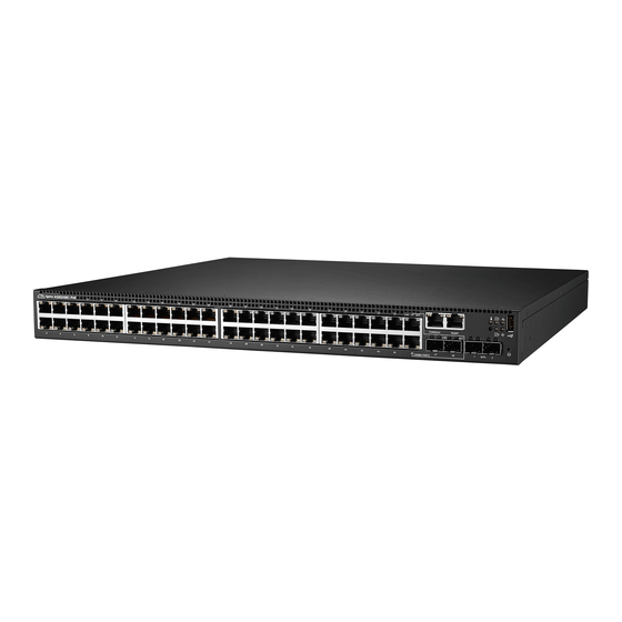
Chapter 1: Introduction Overview AG6248C PoE has 48 10/100/1000BaseT copper ports plus 2 combo SFP ports and 2 SFP+ ports. Each copper port supports auto-sensing and auto negotiation. To further simplify network setups, all ports also automatically sense half- or full-duplex connections for high- speed server or switch-to-switch configurations. -
Page 5: Features
Chapter 1 • Introduction Features The following lists the main features of the AG6248C PoE switch: • 48 x 10/100/1000 BASE-T ports • 2 x combo SFP ports • 2 x 10GbE SFP+ ports • 48 x 1G RJ45 ports are to support PoE+ •... -
Page 6: Chapter 2: Appearance And Mechanism
Redundant PSU x 2 (Figure 2-2: Rear View) NOTE: The switch supports up to two PSUs. However, it is shipped with one power supply pre-installed in the rear panel of the switch. You may purchase an additional PSU for redundancy. AG6248C Power-Over-Ethernet Switch... -
Page 7: Led Identification
Chapter 2 • Appearance and Mechanism LED Identification This section provides an overview of the front and rear LEDs. 2.2.1 Front LEDs Upper 1G BASE-T port LED Console port LED Management port LED 10G SFP+ port LED Power 1/ Power 2 LED Status LED Fan LED 1G combo SFP port LED... - Page 8 LEDs Act LED Off – No link • Blinking Green – Activity, transmitting or receiving packet at this port • Link/SPD LED Console port LED Off – No link • Solid Green – A valid link • AG6248C Power-Over-Ethernet Switch...
- Page 9 Chapter 2 • Appearance and Mechanism 2.2.2 Rear LEDs Power Supply LED (Figure 2-4: Rear LED Identification) Description Off – No power • Power Supply Solid Green – Power is ok • LEDs Solid Red – Power supply is detected but is inadequate •...
-
Page 10: System Requirements
Storm Control • Known & unknown L2MC packets • Known & unknown IPMC packets • Enable individual threshold per port Port requirements Speed Capability per Port 100/1000Mbps Auto-Sensing Full-Duplex Flow Control Support the IEEE 802.3x PAUSE frame AG6248C Power-Over-Ethernet Switch... -
Page 11: Data Center Deployment
PWR1 PWR2 SYS FAN PWR1 PWR2 SYS FAN MGMT MGMT CONSOLE CONSOLE 10G uplink 10G uplink Access Switch Access Switch Access Switch AG6248C AG6248C AG6248C GE downlink with PoE Access Switch Voice IP Security Monitoring (Figure 2-5: Network Deployment) Core Switch Reset Link... -
Page 12: Power Supply Modules
The fan tray module is part of the switch air cooling system that provides cooling for the switch. You must install the fan tray module in the switch that matches the airflow direction of the installed power supply unit. (Figure 2-8: Fan Tray Module) AG6248C Power-Over-Ethernet Switch... -
Page 13: Chapter 3: Installation
Chapter 3: Installation Mounting This switch can be mounted in a standard 19-inch equipment rack or on a horizontal surface. Mounting instructions for each type of site follow. 3.1.1 Rack Mounting Prior rack mounting the switch, pay particular attention to the following factors: •... -
Page 14: Horizontal Surface Mounting
3. If installing a single switch only, go to “ Connecting to a Power Source ”. 4. If installing multiple switches, attach four adhesive feet to each one, then place each device squarely on top of the one below, in any order. AG6248C Power-Over-Ethernet Switch... -
Page 15: Installing An Optional Sfp+ Transceiver
Chapter 3 • Installation Installing an Optional SFP+ Transceiver The SFP+ ports support the following optional SFP+ transceivers: • 10GBASE-CR • 1000BASE-SX • 10GBASE-SR • 1000BASE-LX (Figure 3-4: Inserting an SFP+ Transceiver into a Port) To install an SFP+ transceiver, follow these steps: 1. -
Page 16: Connecting To The Console Port
2. Plug the other end of the cable into a grounded, 3-pin, AC power source. NOTE: For International use, you may need to change the AC line cord. You must use a line cord set that has been approved for the socket type in your country. AG6248C Power-Over-Ethernet Switch... - Page 17 Chapter 3 • Installation 3. Check the PSU and front-panel LEDs as the device is powered on to be sure that AC power is being received and the PWR LED is on. If not, check that the power cable is correctly plugged in.
-
Page 18: Chapter 4: Making The Network Connections
Chapter 4: Making the Network Connections The AG6248C PoE switch is designed to provide Ethernet connections between server racks through its 1G BASE-T or 10G SFP+ ports. This chapter describes how to make network connections to the switch. Twisted-pair Connections The switch’s Management port connection requires an unshielded twisted-pair (UTP) -
Page 19: Fiber Optic Connections
Chapter 4 • Making the Network Connections Fiber Optic Connections Optional 1G SFP or 10G SFP+ transceivers can be used for fiber connections from the switch to other network devices in the data center. A 1G SFP or 10G SFP+ transceiver may also be used for long distance connections to devices at another site. -
Page 20: Appendix 1 : Technical Specifications
434.5 x 407.0 x 43.5 mm Dimensions (W x D x H) • 17.11 x 16.02 x 1.71 inch • 10.5 kg (Net weight) / 11.5 kg (Gross weight) Weight • 23.15 lbs (Net weight) / 25.35 lbs (Gross weight) AG6248C Power-Over-Ethernet Switch... - Page 21 Appendix 1 • Technical Specification Item Description Environmental Specifications Operating temperature 0 to 40°C Storage temperature -20 to 70°C Operating humidity 10 to 90% RH Storage humidity 5 to 95% RH...
-
Page 22: Appendix 2 : Warranty
During the warranty period, products for which proper claims are made will, at Delta’s option, be repaired or replaced at Delta’s expense. Customers may contact Delta’s technical support for warranty services, which may be provided either through Resellers or by Delta directly. -
Page 23: Return Policy
Any product returned to Delta or Resellers without prior Return Material Authorization (RMA) from Delta will be considered an unauthorized return, and you will not receive any repair or replacement for the product and Delta will not ship the product back to you. The authorization will be provided through the e-mail: AgemaTechSupport@deltaww.com.
Need help?
Do you have a question about the AG6248C and is the answer not in the manual?
Questions and answers