
Related Manuals for Delta DVS-103I02C-DLR


Summary of Contents for Delta DVS-103I02C-DLR
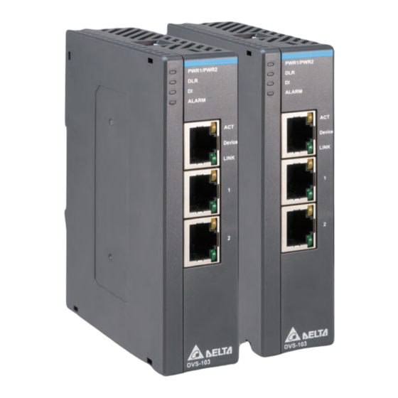
- Page 1 EtherNet/IP DLR Industrial Ethernet Switches DVS-103I02C-DLR Operation Manual www.deltaww.com...
- Page 2 TEL: +7 495 644 3240 Raleigh Office P.O. Box 12173, 5101 Davis Drive, Turkey: Delta Greentech Elektronik San. Ltd. Sti. (Turkey) Research Triangle Park, NC 27709, U.S.A. Şerifali Mah. Hendem Cad. Kule Sok. No:16-A TEL: 1-919-767-3813 / FAX: 1-919-767-3969 34775 Ümraniye – İstanbul Mail: Sales.IA.Turkey@deltaww.com...
- Page 3 EtherNet/IP DLR Industrial Ethernet Switches DVS-103I02C-DLR Operation Manual Revision History Ve r s i o n R e v i s i o n D a t e T h e f i r s t v e r s i o n w a s p u b l i s h e d .
-
Page 4: Table Of Contents
EtherNet/IP DLR Industrial Ethernet Switches DVS-103I02C-DLR Operation Manual Table of Contents Chapter 1 Introduction Introduction ..................1-2 General Specification ................. 1-3 Functional Specification ..............1-4 Communication Interface Specification ..........1-4 1.4.1 Ethernet/IP ..................1-4 Power, Weight and Electric Specification ........... 1-4 Dimensions and parts descriptions ............ - Page 5 Chapter 3 Operation on the Web Overview ................... 3-2 Getting Started .................. 3-2 3.2.1 Exploring the webpage ..............3-2 3.2.2 Using the Webpage ............... 3-3 3.2.3 Login ..................3-4 3.2.4 Menu ..................3-5 Information ..................3-6 3.3.1 Device Information ............... 3-6 Network Configuration ..............
-
Page 6: Chapter 1 Introduction
Chapter 1 Introduction Table of Contents Introduction ..............1-2 General Specification ............1-3 Functional Specification ..........1-4 Communication Interface Specification ......1-4 1.4.1 Ethernet/IP ..................1-4 Power, Weight and Electric Specification ......1-4 Dimensions and parts descriptions ........1-5 Pin Definition and Wiring ..........1-6 Installation .............. -
Page 7: Introduction
D V S - 1 0 3 I 0 2 C - D L R O p e r a t i o n M a n u a l 1.1 Introduction Thank you for choosing Delta DVS-103I02C-DLR. Before using the module, please read this manual for proper installation and operation. -
Page 8: General Specification
C h a p t e r 1 I n t r o d u c t i o n 1.2 General Specification Item Specification Operation temperature -20°C ~ 70°C Storage temperature -40°C ~ 85°C Operation humidity 5~95%, non-condensing Storage humidity 5~95%, non-condensing Operating environment Corrosive gases do not exist... -
Page 9: Functional Specification
D V S - 1 0 3 I 0 2 C - D L R O p e r a t i o n M a n u a l 1.3 Functional Specification Item Specification Maximum number of Device Level Ring nodes ≦... -
Page 10: Dimensions And Parts Descriptions
C h a p t e r 1 I n t r o d u c t i o n 1.6 Dimensions and parts descriptions PWR1 /PWR2 A LARM A CT LIN K D V S-1 0 3 Unit: mm Name Description PWR 1 LED /... -
Page 11: Pin Definition And Wiring
D V S - 1 0 3 I 0 2 C - D L R O p e r a t i o n M a n u a l Name Description Power supply terminal 12~48 VDC power input, digital input and output (alarm) OFF / OFF: Use EIP Builder to set up the IP address ON / OFF: Use BOOTP to set up the IP address DIP1 &... - Page 12 C h a p t e r 1 I n t r o d u c t i o n • RJ-45 terminal block Diagram Terminal no. Definition Description Transmit data + Transmit data - Receive data + Receive data - 1 - 7...
-
Page 13: Installation
To dismantle, first push down the device in arrow ① direction and follow arrow ③ direction to release the device. Rail Note: When installing DVS-103I02C-DLR on the Din Rail, it is required to leave a space of 5 cm among devices. Do not block top or bottom ventilation openings. 1 - 8... -
Page 14: Network Topology
C h a p t e r 1 I n t r o d u c t i o n 1.9 Network Topology Linear Topology Star Topology Ring Topology A DLR function is required to create a ring topology. When a switch is needed for the particular topology, the switch should support the DLR function. - Page 15 D V S - 1 0 3 I 0 2 C - D L R O p e r a t i o n M a n u a l The EtherNet/IP DLR Industrial Ethernet Switch, DVS-103I02C-DLR, supports DLR function. Use the communication port named port 1 and port 2 to connect DLR network.
- Page 16 Chapter 2 Software Configuration Table of Contents Software Configuration ........... 2-2 2.1.1 Software description ..............2-2 2.1.2 Procedures ................... 2-2 Parameter Settings ............2-4 2.2.1 Device Parameters ................ 2-4 2.2.1.1 Ring Status .................. 2-5 2.2.1.2 Port 1, Port 2, and Device Port ............. 2-6 2.2.1.3 Alarm ..................
-
Page 17: Software Configuration
D V S - 1 0 3 I 0 2 C - D L R O p e r a t i o n M a n u a l 2.1 Software Configuration 2.1.1 Software description Users must install two basic software – EIP Builder (V1.07 or later) and COMMGR (V1.10 or later) before operating the modules. - Page 18 C h a p t e r 2 S o f t wa r e C o n f i g u r a t i o n Step 4: Double-click or drag and drop DVS-103I02C-DLR to add the device to the section of Network View.
-
Page 19: Parameter Settings
D V S - 1 0 3 I 0 2 C - D L R O p e r a t i o n M a n u a l 2.2 Parameter Settings Parameter settings include EIP Parameter and Device Parameter. You need to be in On-Line mode to edit and view the EIP parameters. -
Page 20: Ring Status
C h a p t e r 2 S o f t wa r e C o n f i g u r a t i o n 2.2.1.1 Ring Status Click “Ring Status” under the Device Parameter tab, you can see all parameters of the ring topology. Name Description Current network topology... -
Page 21: Port 1, Port 2, And Device Port
D V S - 1 0 3 I 0 2 C - D L R O p e r a t i o n M a n u a l 2.2.1.2 Port 1, Port 2, and Device Port Click “Port 1” or “Port 2” under the Device Parameter tab, you can see the port-related information. 2.2.1.3 Alarm Click “Alarm”... -
Page 22: Eip Parameters
Click “IP Setting” under the EIP Parameter tab, you can set up IP-related settings. You can also set up the IP settings through DIP 1 and 2. But you need to turn DVS-103I02C-DLR power off and then on again to complete the setting. -
Page 23: Connection
Click “DLR” under the EIP Parameter tab, you can see the DLR information, including DLR Network information, DLR Network Diagnostics, and Ring Supervisor Configuration Parameters. You can use DIP 3 to enable or disable the Ring Supervisor function. But you need to turn DVS-103I02C-DLR power off and then on again to complete the setting. - Page 24 C h a p t e r 2 S o f t wa r e C o n f i g u r a t i o n Name Description DLR Network Information DLR network information is shown here. Current network topology Linear Network Topology Ring...
- Page 25 D V S - 1 0 3 I 0 2 C - D L R O p e r a t i o n M a n u a l Name Description Last Active Node on Port 1 Here shows the IP address and the MAC address of the last active node on Port 1. Last Active Node on Port 2 Here shows the IP address and the MAC address of the last active node on Port 2.
- Page 26 Chapter 3 Operation on the Web Table of Contents Overview ................... 3-2 Getting Started .................. 3-2 3.2.1 Exploring the webpage ..............3-2 3.2.2 Using the Webpage ............... 3-3 3.2.3 Login................... 3-4 3.2.4 Menu ..................3-5 Information ..................3-6 3.3.1 Device Information ................ 3-6 Network Configuration ..............
-
Page 27: Overview
This chapter introduces IABG Ethernet Web Solution and how to operate in this environment. Getting Started You can enter DVS-103I02C-DLR IP address in the search bar of your browser to connect to your device. After that you can set up and DVS-103I02C-DLR. -
Page 28: Using The Webpage
C h a p t e r 3 O p e r a t i o n o n t h e We b 3.2.2 Using the Webpage List of browsers that support IABG Web Solution webpage: Provider Browser Supported versions Internet Explorer V10.0 and later Microsoft... -
Page 29: Login
D V S - 1 0 3 I 0 2 C - D L R O p e r a t i o n M a n u a l 3.2.3 Login You need to login to your account to set up. ... -
Page 30: Menu
C h a p t e r 3 O p e r a t i o n o n t h e We b 3.2.4 Menu The menu shows data based on the permission of the current user. Permission Nodes Administrator Read Device information... -
Page 31: Information
D V S - 1 0 3 I 0 2 C - D L R O p e r a t i o n M a n u a l Information Here provides DVS-103I02C-DLR product information. 3.3.1 Device Information You do not need to log in to see the device information. This page is read only, not for editing. -
Page 32: Network Configuration
C h a p t e r 3 O p e r a t i o n o n t h e We b Network Configuration You can set network related configurations here. 3.4.1 Account Management You can set 2 kinds of access types for up to 8 user accounts. Item Description To name your user ID, you can use up to 16 characters from the following characters, A... - Page 33 D V S - 1 0 3 I 0 2 C - D L R O p e r a t i o n M a n u a l Operation Steps: After log in, double-click Account management to open the setting page. Set up the User ID, the password and the access type.
- Page 34 C h a p t e r 3 O p e r a t i o n o n t h e We b Double-click Save configuration to open the setting page. Click “Save” to save and download the settings to the device. e.
-
Page 35: Firmware Update
D V S - 1 0 3 I 0 2 C - D L R O p e r a t i o n M a n u a l 3.4.2 Firmware Update You can set network related configurations here. Item Description Choose file... - Page 36 C h a p t e r 3 O p e r a t i o n o n t h e We b Item Description Refresh cycle Refresh cycle time; default 10 seconds Use this button to decrement the setting number. The minimum value is 1 “-”...
-
Page 37: Save Configuration
D V S - 1 0 3 I 0 2 C - D L R O p e r a t i o n M a n u a l Item Description 1 MAC address Last active node on port Here shows the IP address of the last active node on Port 2. - Page 38 Chapter 4 Troubleshooting Table of Contents Troubleshooting .................. 4-2 4.1.1 Clear the Error States ..............4-2 4.1.2 DLR Status Indicator ..............4-2 4.1.3 Alarm Status Indicators ..............4-2 4 - 1...
- Page 39 D V S - 1 0 3 I 0 2 C - D L R O p e r a t i o n M a n u a l 4.1 Troubleshooting This chapter includes the possible errors that can occur during operation and the causes or responses in handling these situations.
Need help?
Do you have a question about the DVS-103I02C-DLR and is the answer not in the manual?
Questions and answers