Table of Contents
Advertisement
Quick Links
Advertisement
Table of Contents

Related Manuals for Delta Agema AG5648


Summary of Contents for Delta Agema AG5648
- Page 1 Delta Networking – Agema Family AG5648 Leaf/ToR Switch Installation Guide...
- Page 2 Copyright All specifications and figures are subject to change without prior notice. Actual products may look different from the photos. All trademarks and logos mentioned in this guide are the properties of their respective holders. Copyright © 2017 Agema Systems Inc. All rights reserved. Regulatory and Safety Information This product has been tested in accordance to, and complies with the following safety standards and electromagnetic compatibility (EMC) inspection standards.
-
Page 3: Table Of Contents
Table of Contents Table of Contents Chapter 1: Introduction -------------------------------------------------------------------1 1.1 Overview ------------------------------------------------------------------------------------ 1 1.2 Package Content -------------------------------------------------------------------------- 1 1.3 Features ------------------------------------------------------------------------------------- 2 Chapter 2: Appearance and Mechanism --------------------------------------------3 2.1 Product Overview ------------------------------------------------------------------------- 3 2.2 LED Identification ------------------------------------------------------------------------- 4 2.3 System Requirements ------------------------------------------------------------------- 6 2.4 Data Center Deployment ---------------------------------------------------------------- 7 2.5 Power Supply Modules ------------------------------------------------------------------ 7 2.6 Fan Tray Module -------------------------------------------------------------------------- 8... -
Page 4: Chapter 1: Introduction
Chapter 1: Introduction Overview The AG5648 is next generation leaf/ToR switch for Data Center Networks, as well as Enterprise network deployments. It leverage the 100G technology (4x25G Serdes) to provide 48-port 25G SFP28 and 6-port 100G QSFP28 in a compact 1RU form factor with 2.5 times speed upgrade from current 10Gigabits leaf/ToR switch. -
Page 5: Features
Chapter 1 • Introduction Features The following lists the key main features of the AG5648 switch: • 48 x 25GbE SFP28 ports • 6 x 100GbE QSFP28 ports • 1 x OOB Management • 1 x Console port (RJ-45 type) •... -
Page 6: Chapter 2: Appearance And Mechanism
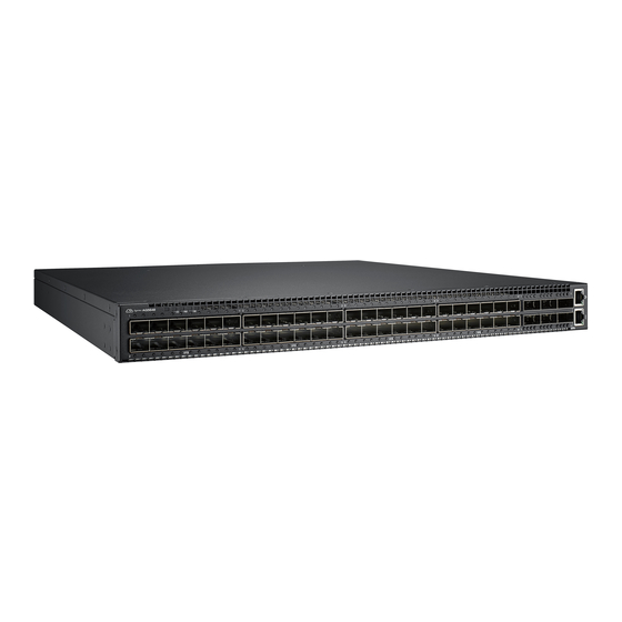
Chapter 2: Appearance and Mechanism Product Overview 2.1.1 Front View RJ-45 Console port x 1 Management port x 1 SFP28 port x 48 QSFP28 port x 6 (Figure 2-1: Front View) 2.1.2 Rear View 4 Fan tray slots USB port x 1 Reset x 1 Secondary PSU PSU x 1... -
Page 7: Led Identification
Chapter 2 • Appearance and Mechanism LED Identification This section provides an overview of the front and rear LEDs. 2.2.1 Front LEDs System LED Power LED Upper QSFP28 Port LED Fan Status LED Upper SFP28 Port LED Lower SFP28 Port LED Lower QSFP28 Port LED (Figure 2-3: Front LED Identification) Description... -
Page 8: Link Led
Description LED1 Off – No link • Solid Green – A valid 100G link • Solid Amber – A valid 40G link • Solid Blue – A valid 10Gbps link • 100G QSFP28 Solid Purple – A 10Gbps link • slots LED 2 and 4 (working in breakout) Off –... -
Page 9: System Requirements
Chapter 2 • Appearance and Mechanism System Requirements Component Requirement System requirements Switch fabric capacity Non-blocking full wire speed on all packet sizes Forwarding architecture Store and forward or cut-through Port packet forwarding rate 14880000 pps (10Gb) (at 64 Bytes) MAC address entries Up to 136K entries supported... -
Page 10: Data Center Deployment
Data Center Deployment The following figure illustrates the converaged Ethernet data center deployment. AG9032 v1 AG9032 v1 AG9032 v1 AG9032 v1 Spine 6x100G uplink AG5648 AG5648 AG5648 AG9032 v1 Leaf 25G downlink 25G downlink 25G downlink 25G downlink via Breakout cable (Figure 2-5: Converaged Ethernet Data Center Deployment) Power Supply Modules The power supply modules are hot-swappable power supply units (PSUs) for the switch. -
Page 11: Fan Tray Module
Chapter 2 • Appearance and Mechanism Fan Tray Module The fan tray module is part of the switch air cooling system that provides cooling for the switch. You must install the fan tray module in the switch that matches the airflow direction of the installed power supply unit. -
Page 12: Chapter 3: Installation
Chapter 3: Installation Mounting This switch can be mounted in a standard 19-inch equipment rack or on a horizontal surface. Mounting instructions for each type of site follow. 3.1.1 Rack Mounting Prior rack mounting the switch, pay particular attention to the following factors: •... -
Page 13: Horizontal Surface Mounting
Chapter 3 • Installation (Figure 3-2: Installing the Switch in a Rack) 3. If installing a single switch only, go to “ Connecting to a Power Source ”. 4. If installing multiple switches, mount them in the rack, one below the other, in any order. 3.1.2 Horizontal Surface Mounting The switch includes four pre-installed rubber feet for horizontal surface mounting. -
Page 14: Installing An Optional Transceiver And Cable
Installing an Optional Transceiver and Cable The SFP28 slots support the following optional transceivers and cables: • 25GBASE-SR • 10GBASE-SR • 25GBASE-LR • 10GBASE-LR • 25GBASE AOC • 10GBASE AOC • 25GBASE DAC • 10GBASE DAC The QSFP28 slots support the following optional transceivers and cables: •... -
Page 15: Connecting To The Console Port
Chapter 3 • Installation 3. Slide the SFP+, SFP28, QSFP or QSFP28 transceiver into the slot until it clicks into place. NOTE: • SFP+, SFP28, QSFP or QSFP28 transceivers are hot-swappable. The switch does not need to be powered off before installing or removing a transceiver. -
Page 16: Connecting To A Power Source
Connecting to a Power Source 3.4.1 Installing an AC Power Supply To connect a switch to a power source: 1. Insert the power cable plug directly into the AC socket of a PSU located at the back of the switch. Power socket (Figure 3-7: Power Socket) 2. - Page 17 Chapter 3 • Installation 2. Plug the other end of the cable into DC power source. This product is intended to be supplied by DC power source with rated -40 ~ -72Vdc, 16A minimum, Tma = 40 degree C, and the altitude of operation = 3048 m. The power cable should be 14AWG (16A minimum, 72V minimum).
-
Page 18: Chapter 4: Making The Network Connections
Chapter 4: Making the Network Connections The AG5648 switch is designed to provide high-speed, lossless Ethernet connections between server racks through its 25G SFP28 or 100G QSFP28 ports. This chapter describes how to make network connections to the switch. Twisted-pair Connections The switch’s Management port connection requires an unshielded twisted-pair (UTP) cable with RJ-45 connectors at both ends. -
Page 19: Fiber Optic Connections
Chapter 4 • Making the Network Connections Fiber Optic Connections Optional 25G SFP28 or 100G QSFP28 transceivers can be used for fiber connections from the switch to other network devices in the data center. An SFP28 or QSFP28 transceiver may also be used for long distance connections to devices at another site. -
Page 20: Ethernet Cabling
Ethernet Cabling To ensure proper operation when installing the switch into a network, make sure that the current cables are suitable for 10BASE-T, 100BASE-TX or 1000BASE-T operation. Check the following criteria against the current installation of your network: • Cable type: Unshielded twisted pair (UTP) or shielded twisted pair (STP) cables with RJ- 45 connectors;... -
Page 21: Appendix 1 : Technical Specifications
Appendix 1 : Technical Specifications Item Description Key components Switch controller BCM56963 x 1 BCM5461S x 1 Intel Rangley C2538 2.4Ghz Flash ROM 16 MB SPI Flash System memory 4GB DDR3 SO-DIMM mSATA Device 8GB SSD Network Protocol and Standards Compatibility •... -
Page 22: Appendix 2 : Warranty
Appendix 2 : Warranty Limited and Support Warranty Three Years End-User Guarantee. The new product you purchased from Agema or Agema authorized resellers (“Resellers”) will be free from defects in materials, workmanship, and design affecting normal use, for a period of three (3) years from the original purchase date. -
Page 23: Return Policy
Appendix 2 • Warranty Return Policy Any product returned to Agema or Resellers without prior Return Material Authorization (RMA) from Agema will be considered an unauthorized return, and you will not receive any repair or replacement for the product and Agema will not ship the product back to you. The authorization will be provided through the e-mail: techsupport@agemasystems.com.
Need help?
Do you have a question about the Agema AG5648 and is the answer not in the manual?
Questions and answers