Table of Contents
Advertisement
Industrial Automation Headquarters
Delta Electronics, Inc.
Taoyuan Technology Center
No.18, Xinglong Rd., Taoyuan City,
Taoyuan County 33068, Taiwan
TEL: 886-3-362-6301 / FAX: 886-3-371-6301
Asia
Delta Electronics (Jiangsu) Ltd.
Wujiang Plant 3
1688 Jiangxing East Road,
Wujiang Economic Development Zone
Wujiang City, Jiang Su Province, P.R.C. 215200
TEL: 86-512-6340-3008 / FAX: 86-769-6340-7290
Delta Greentech (China) Co., Ltd.
238 Min-Xia Road, Pudong District,
ShangHai, P.R.C. 201209
TEL: 86-21-58635678 / FAX: 86-21-58630003
Delta Electronics (Japan), Inc.
Tokyo Office
2-1-14 Minato-ku Shibadaimon,
Tokyo 105-0012, Japan
TEL: 81-3-5733-1111 / FAX: 81-3-5733-1211
Delta Electronics (Korea), Inc.
1511, Byucksan Digital Valley 6-cha, Gasan-dong,
Geumcheon-gu, Seoul, Korea, 153-704
TEL: 82-2-515-5303 / FAX: 82-2-515-5302
Delta Electronics Int'l (S) Pte Ltd.
4 Kaki Bukit Ave 1, #05-05, Singapore 417939
TEL: 65-6747-5155 / FAX: 65-6744-9228
Delta Electronics (India) Pvt. Ltd.
Plot No 43 Sector 35, HSIIDC
Gurgaon, PIN 122001, Haryana, India
TEL : 91-124-4874900 / FAX : 91-124-4874945
Americas
Delta Products Corporation (USA)
Raleigh Office
P.O. Box 12173,5101 Davis Drive,
Research Triangle Park, NC 27709, U.S.A.
TEL: 1-919-767-3800 / FAX: 1-919-767-8080
Delta Greentech (Brasil) S.A.
Sao Paulo Office
Rua Itapeva, 26 - 3° andar Edificio Itapeva One-Bela Vista
01332-000-São Paulo-SP-Brazil
TEL: 55 11 3568-3855 / FAX: 55 11 3568-3865
Europe
Deltronics (The Netherlands) B.V.
Eindhoven Office
De Witbogt 15, 5652 AG Eindhoven, The Netherlands
TEL: 31-40-2592850 / FAX: 31-40-2592851
V 0.01.01.001
*We reserve the right to change the information in this manual without prior notice.
DVS Series Unmanaged
Industrial Ethernet
Switches User's Manual
2013-11-07
www.deltaww.com
Advertisement
Table of Contents

Subscribe to Our Youtube Channel
Related Manuals for Delta DVS Series


Summary of Contents for Delta DVS Series
- Page 1 1511, Byucksan Digital Valley 6-cha, Gasan-dong, Geumcheon-gu, Seoul, Korea, 153-704 DVS Series Unmanaged TEL: 82-2-515-5303 / FAX: 82-2-515-5302 Delta Electronics Int’l (S) Pte Ltd. 4 Kaki Bukit Ave 1, #05-05, Singapore 417939 Industrial Ethernet TEL: 65-6747-5155 / FAX: 65-6744-9228 Delta Electronics (India) Pvt. Ltd.
-
Page 2: Table Of Contents
DVS Series Unmanaged Industrial Ethernet Switches User’s Manual Table of Contents Chapter 1 Overview 1.1 Features ..................1-2 1.2 Package Checklist ................1-2 Chapter 2 Hardware Description 2.1 Panel Layout ...................2-2 2.2 Dimension ..................2-24 2.3 LED Indicators ................2-25 2.4 Wiring the Redundant Power Inputs ..........2-26 2.5 Wiring the Alarm Contact ...............2-27... -
Page 4: Chapter 1 Overview
Chapter 1 Overview Table of Contents Features ....................1-2 Package Checklist ..................1-2 1 - 1... -
Page 5: Features
---Consult the dealer or an experienced radio/TV technician for help. CE Declaration of Conformity The DVS series switches are CE certificated products, they could use in any kind of the environments under CE environment specification. For keeping more safe application, we strongly suggest to use the CE-compliant industrial enclosure products. - Page 6 Ch ap te r 1 O ver view please contact your customer service representative for assistance. .Delta DVS Unmanaged Ethernet Switch .Instruction Sheet .Wall mounting Plate .Protective Caps for unused RJ45 ports 1 - 3...
- Page 7 D VS Ser ies In dus tr ia l Ethe rne t Sw itches MEMO 1 - 4...
-
Page 8: Chapter 2 Hardware Description
Chapter 2 Hardware Description Table of Contents Panel Layout .....................2-2 Dimension ....................2-24 LED Indicators..................2-25 Wiring the Redundant Power Inputs ............2-26 Wiring the Alarm Contact.................2-27 Ethernet Interface..................2-27 DIP Switch Setting...................2-28 2 - 1... -
Page 9: Panel Layout
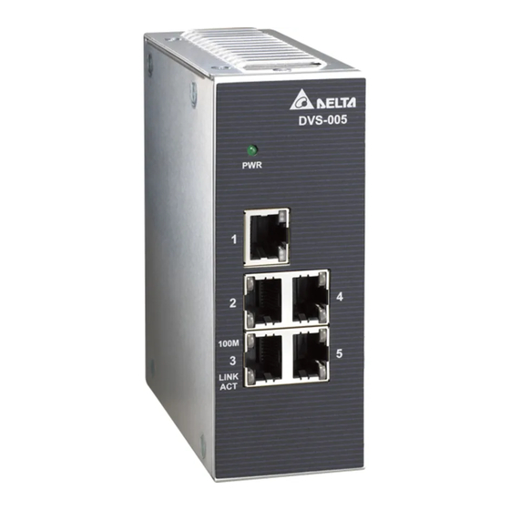
D VS Ser ies In dus tr ia l Ethe rne t Sw itches 2.1 Panel Layout DVS-005I00 Front Panel Power LED LINK/ACT LED Ethernet port Series model name Speed LED 2 - 2... - Page 10 Chapter 2 Har dware Descr iption Bottom panel Terminal Block of PWR Grounding screw 2 - 3...
- Page 11 D VS Ser ies In dus tr ia l Ethe rne t Sw itches DVS-G005I00A Front Panel Power LED LINK/ACT LED Ethernet port Series model name Speed LED 2 - 4...
- Page 12 Chapter 2 Har dware Descr iption Bottom panel Terminal Block of PWR Grounding screw 2 - 5...
- Page 13 D VS Ser ies In dus tr ia l Ethe rne t Sw itches DVS-005W01 Front Panel Event alarm DIP Switch Speed LED LED (ALARM / PWR1 / PWR2) LINK/ACT LED Ethernet port Series model name 2 - 6...
- Page 14 Chapter 2 Har dware Descr iption Bottom panel Terminal block of alarm output Terminal block of PWR2 Terminal Block of PWR1 Grounding screw 2 - 7...
- Page 15 D VS Ser ies In dus tr ia l Ethe rne t Sw itches DVS-005W01-MC01 / DVS-005W01-SC01 Front Panel Event alarm DIP Switch Speed LED LED (ALARM / PWR1 / PWR2 / Fiber port speed LED) LINK/ACT LED Fiber Ethernet port Series model name Ethernet port 2 - 8...
- Page 16 Chapter 2 Har dware Descr iption Bottom panel Terminal block of alarm output Terminal Block of PWR2 Terminal Block of PWR1 Grounding screw 2 - 9...
- Page 17 D VS Ser ies In dus tr ia l Ethe rne t Sw itches DVS-008I00 Front Panel Power LED LINK/ACT LED Ethernet port Series model name Speed LED 2 - 1 0...
- Page 18 Chapter 2 Har dware Descr iption Bottom panel Terminal Block of PWR Grounding screw 2 - 11...
- Page 19 D VS Ser ies In dus tr ia l Ethe rne t Sw itches DVS-G008I00A Front Panel Power LED LINK/ACT LED Ethernet port Series model name Speed LED 2 - 1 2...
- Page 20 Chapter 2 Har dware Descr iption Bottom panel Terminal Block of PWR Grounding screw 2 - 1 3...
- Page 21 D VS Ser ies In dus tr ia l Ethe rne t Sw itches DVS-008W01 Front Panel Event alarm DIP Switch Speed LED LED (ALARM / PWR1 / PWR2) LINK/ACT LED Ethernet port Series model name 2 - 1 4...
- Page 22 Chapter 2 Har dware Descr iption Bottom panel Terminal block of alarm output Terminal Block of PWR2 Terminal Block of PWR1 Grounding screw 2 - 1 5...
- Page 23 D VS Ser ies In dus tr ia l Ethe rne t Sw itches DVS-008W01-MC01 / DVS-008W01-SC01 Front Panel Event alarm DIP Switch Speed LED LED (ALARM / PWR1 / PWR2 / Fiber port speed LED) LINK/ACT LED Fiber Ethernet port Series model name Ethernet port 2 - 1 6...
- Page 24 Chapter 2 Har dware Descr iption Bottom panel Terminal block of alarm output Terminal Block of PWR2 Terminal Block of PWR1 Grounding screw 2 - 1 7...
- Page 25 D VS Ser ies In dus tr ia l Ethe rne t Sw itches DVS-008W01-MC02 / DVS-008W01-SC02 Front Panel Event alarm DIP Switch Speed LED LED (ALARM / PWR1 / PWR2 / Fiber port speed LED) LINK/ACT LED Fiber Ethernet port Series model name Ethernet port 2 - 1 8...
- Page 26 Chapter 2 Har dware Descr iption Bottom panel Terminal block of alarm output Terminal Block of PWR2 Terminal Block of PWR1 Grounding screw 2 - 1 9...
- Page 27 D VS Ser ies In dus tr ia l Ethe rne t Sw itches DVS-016W01 Front Panel Event alarm DIP Switch Speed LED LED (ALARM / PWR1 / PWR2) LINK/ACT LED Ethernet port Series model name 2 - 2 0...
- Page 28 Chapter 2 Har dware Descr iption Bottom panel Terminal block of alarm output Terminal Block of PWR2 Terminal Block of PWR1 Grounding screw 2 - 2 1...
- Page 29 D VS Ser ies In dus tr ia l Ethe rne t Sw itches DVS-016W01-MC01 / DVS-016W01-SC01 Front Panel Event alarm DIP Switch Speed LED LED (ALARM / PWR1 / PWR2 / Fiber port speed LED) LINK/ACT LED Fiber Ethernet port Series model name Ethernet port 2 - 2 2...
- Page 30 Chapter 2 Har dware Descr iption Bottom panel Terminal block of alarm output Terminal Block of PWR2 Terminal Block of PWR1 Grounding screw 2 - 2 3...
-
Page 31: Dimension
D VS Ser ies In dus tr ia l Ethe rne t Sw itches 2.2 Dimension DVS-005I00/DVS-008I00/G005I00A/G008I00A /005W01/005W01-MC01/005W01-SC01 145.3(H) x 45(W) x 108.7(D) mm DVS-008W01/008W01-MC01/008W01-SC01/008W01-MC02/008W01-SC02 145.3(H) x 75(W) x 108.7(D) mm 2 - 2 4... -
Page 32: Led Indicators
Chapter 2 Har dware Descr iption DVS-016W01/016W01-MC01/016W01-SC01 145.3(H) x 75(W) x 108.7(D) mm 2.3 LED Indicators DVS-005I00 / DVS-008I00 / G005I00A / G008I00A Color Status Description The power is supplied normally. Green The power is not supplied. The port is connected at a speed of 100 Mbps. 100M Orange The port is connected at a speed of 10 Mbps or disconnected. -
Page 33: Wiring The Redundant Power Inputs
2.4 Wiring the Redundant Power Inputs Except the DVS-005I00, the DVS series switches are equipped with two sets of DC input (PWR1 / PWR2). Both sets of DC input can be connected to a wide range of power sources (12 to 48VDC). If one power source fails, the other live source can work as a backup to ensure that the machine operates normally. -
Page 34: Wiring The Alarm Contact
2.6 Ethernet Interface 10/100Base-T(X) Connection The 10/100Base-T(X) ports of the DVS series switches are used to connect to Ethernet. They can support MDI (NIC–type) and MDI-X (HUB/Switch-type) modes, the pin definition of the Ethernet cable is as follows. MDI Mode Definition... -
Page 35: Dip Switch Setting
D VS Ser ies In dus tr ia l Ethe rne t Sw itches 100Base-FX Connection The products are US FDA CDRH AEL Class 1 product. The output signal of the fiber port will damage the eyes Do not look directly at the fiber port. In your fiber connection application, the RX port of DVS switches must connect to the TX port of the other fiber device and the TX port of DVS switches must connect to the RX port of the other fiber device. -
Page 36: Chapter 3 Installation
Chapter 3 Installation Table of Contents DIN-Rail Mounting ..................3-2 Wall Mounting....................3-3 3 - 1... -
Page 37: Din-Rail Mounting
Mounting Step 1: Hook the upper end of the DIN clip of the DVS series switch on the DIN-Rail. Step 2: Lightly push the DVS series switch toward the DIN-Rail until they contact each other closely. -
Page 38: Wall Mounting
Ch ap te r 3 Ins ta lla tion 3.2 Wall Mounting Step 1: Insert the wall mounting bracket into the slot on the rear panel of the DVS series switch, and tighten the screw on it, as shown in the diagram below. -
Page 39: Chapter 4 Functional Description
Chapter 4 Functional Description Table of Contents Auto MDI/MDI-X Connection ..............4-2 Auto-Negotiation and Speed Sensing............4-2 Stored and Forward...................4-2 Addresses Capability and Learning ............4-2 Quality of Service and VLAN Tagging............4-2 Broadcast Control..................4-2 4 - 1... -
Page 40: Auto Mdi/Mdi-X Connection
D VS Ser ies In dus tr ia l Ethe rne t Sw itches 4.1 Auto MDI/MDI-X Connection The Auto MDI/MDI-X function let users connect DVS switches’ 10/100Base-T(X) ports to any kind of Ethernet device. You don’t need to pay attention to the type of Ethernet cable being used for the connection.
Need help?
Do you have a question about the DVS Series and is the answer not in the manual?
Questions and answers