Table of Contents
Advertisement
Quick Links
Industrial Automation Headquarters
Delta Electronics, Inc.
Taoyuan Technology Center
No.18, Xinglong Rd., Taoyuan City,
Taoyuan County 33068, Taiwan
TEL: 886-3-362-6301 / FAX: 886-3-371-6301
Asia
Delta Electronics (Jiangsu) Ltd.
Wujiang Plant 3
1688 Jiangxing East Road,
Wujiang Economic Development Zone
Wujiang City, Jiang Su Province, P.R.C. 215200
TEL: 86-512-6340-3008 / FAX: 86-769-6340-7290
Delta Greentech (China) Co., Ltd.
238 Min-Xia Road, Pudong District,
ShangHai, P.R.C. 201209
TEL: 86-21-58635678 / FAX: 86-21-58630003
Delta Electronics (Japan), Inc.
Tokyo Office
2-1-14 Minato-ku Shibadaimon,
Tokyo 105-0012, Japan
TEL: 81-3-5733-1111 / FAX: 81-3-5733-1211
Delta Electronics (Korea), Inc.
1511, Byucksan Digital Valley 6-cha, Gasan-dong,
Geumcheon-gu, Seoul, Korea, 153-704
TEL: 82-2-515-5303 / FAX: 82-2-515-5302
Delta Electronics Int'l (S) Pte Ltd.
4 Kaki Bukit Ave 1, #05-05, Singapore 417939
TEL: 65-6747-5155 / FAX: 65-6744-9228
Delta Electronics (India) Pvt. Ltd.
Plot No 43 Sector 35, HSIIDC
Gurgaon, PIN 122001, Haryana, India
TEL : 91-124-4874900 / FAX : 91-124-4874945
Americas
Delta Products Corporation (USA)
Raleigh Office
P.O. Box 12173,5101 Davis Drive,
Research Triangle Park, NC 27709, U.S.A.
TEL: 1-919-767-3800 / FAX: 1-919-767-8080
Delta Greentech (Brasil) S.A.
Sao Paulo Office
Rua Itapeva, 26 - 3° andar Edificio Itapeva One-Bela Vista
01332-000-São Paulo-SP-Brazil
TEL: 55 11 3568-3855 / FAX: 55 11 3568-3865
Europe
Deltronics (The Netherlands) B.V.
Eindhoven Office
De Witbogt 15, 5652 AG Eindhoven, The Netherlands
TEL: 31-40-2592850 / FAX: 31-40-2592851
V 1.01.01.001
*We reserve the right to change the information in this manual without prior notice.
DVS Series Managed
Industrial Ethernet
Switches User's Manual
2013-10-30
www.deltaww.com
Advertisement
Table of Contents

Subscribe to Our Youtube Channel
Related Manuals for Delta DVS Series


Summary of Contents for Delta DVS Series
- Page 1 1511, Byucksan Digital Valley 6-cha, Gasan-dong, DVS Series Managed Geumcheon-gu, Seoul, Korea, 153-704 TEL: 82-2-515-5303 / FAX: 82-2-515-5302 Delta Electronics Int’l (S) Pte Ltd. Industrial Ethernet 4 Kaki Bukit Ave 1, #05-05, Singapore 417939 TEL: 65-6747-5155 / FAX: 65-6744-9228 Delta Electronics (India) Pvt. Ltd.
-
Page 2: Table Of Contents
DVS Series Managed Industrial Ethernet Switches User’s Manual Contents Chapter 1 Introduction Feature ......................1-2 1.1.1 High Performance Network Technology..........1-2 1.1.2 Industrial Grade Reliability ..............1-2 1.1.3 Robust Design..................1-2 1.1.4 Front Panel Ports and LEDs...............1-3 1.1.5 Below Panel ..................1-3 SFP Module Installation................1-4 Package Checklist ..................1-5... - Page 3 3.1.6.1 DNS Configuration..............3-22 3.1.6.2 Host Configuration ..............3-23 3.1.7 System File Update................3-24 3.1.7.1 Download File ................3-24 3.1.7.2 Upload File................3-26 3.1.8 Management Access................3-27 3.1.8.1 HTTP Configuration ..............3-27 3.1.8.2 HTTPS ..................3-28 3.1.8.3 SSH Configuration ..............3-31 3.1.8.4 Telnet Configuration ..............
- Page 4 3.5.5 GMRP Configuration ................3-67 3.5.6 Multicast Forwarding Table...............3-68 Traffic Prioritization..................3-68 3.6.1 QoS ....................3-68 3.6.1.1 QoS Setting................3-69 3.6.1.2 CoS Queue Mapping..............3-70 3.6.1.3 DSCP Queue Mapping..............3-71 Traffic Control..................3-72 3.7.1 Port Protected ..................3-72 Port Bandwidth ..................3-72 3.8.1 Storm Control ...................3-72 3.8.1.1 Storm Control Setting ..............3-73 3.8.1.2 Rate Limiting ................3-74 Port Trunking...................3-75...
- Page 5 3.12.2 SFP DDM..................3-100 3.12.3 System CPU Status ............... 3-100 3.12.4 Interface Statistics................3-101 3.12.5 RMON.................... 3-101 3.12.5.1 Basic Settings .................3-101 3.12.5.2 Alarms..................3-102 3.12.5.3 Events..................3-104 3.12.5.4 Event Log................3-104 3.12.5.5 History..................3-105 3.12.5.6 RMON Ethernet Statistics ............3-105 3.12.5.7 Ethernet History Statistics ............
- Page 6 3.16.2 Erase....................3-131 3.17 Reset .....................3-131 3.17.1 Device Reboot................3-131 3.17.2 Factory Default Settings ..............3-131 3.18 Troubleshooting..................3-132 3.18.1 Ping IPv4..................3-132 3.18.2 Ping IPv6..................3-133 3.18.3 Traceroute IPv4................3-134 3.18.4 Traceroute IPv6................3-134 Chapter 4 IEXplorer Utility Introduction Starting the Configuration................4-2 Device .......................4-3 4.2.1 Search....................4-4 Settings .....................4-4 4.3.1 Device Configuration ................4-5 4.3.2...
-
Page 8: Chapter 1 Introduction
Chapter 1 Introduction Table of Contents Feature ......................1-2 1.1.1 High Performance Network Technology ..........1-2 1.1.2 Industrial Grade Reliability ..............1-2 1.1.3 Robust Design..................1-2 1.1.4 Front Panel Ports and LEDs...............1-3 1.1.5 Bottom Panel..................1-3 SFP Module Installation................1-4 Package Checklist ..................1-5 1 - 1... -
Page 9: Feature
---Consult the dealer or an experienced radio/TV technician for help. CE Declaration of Conformity The DVS series switches are CE certificated products. They could be used in any kind of the environments under CE environment specification. For keeping more safe application, we strongly suggest to use the CE-compliant industrial enclosure products. -
Page 10: Front Panel Ports And Leds
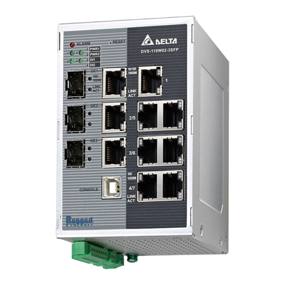
Ch ap te r 1 In tro duc tio n 1.1.4 Front Panel Ports and LEDs Reset Button Alarm LED PWR LED Model Name DI LED Speed LED SFP combo ports Link/Act LED RJ45 ports USB console port 1.1.5 Bottom Panel Grounding Screw DI &... -
Page 11: Sfp Module Installation
Remove: Pull the tab on the module, and then pull out it. Note: Delta has LCP-155 and LCP-1250 series SFP module. DVS switch can promise 100% compatible with Delta SFP module. Note: The actual link distance of a particular fiber optic link given the optical budget, the number of connectors and splices, and cabling quantity. -
Page 12: Package Checklist
Ch ap te r 1 In tro duc tio n 1.3 Package Checklist One Delta DVS Managed Ethernet Switch Protective Caps for unused RJ45 ports DIN-Rail clip x1 Wall mounting Plate x1 USB Type A to Type B console cable x1 ... - Page 13 D VS Ser ies Man age d In dus tr ia l Eth erne t Sw itches Use r ’s Ma nual MEMO 1 - 6...
-
Page 14: Chapter 2 User Interface Introduction
Chapter 2 User Interface Introduction Table of Contents USB Console Configuration...............2-2 Telnet Console Configuration ..............2-4 Web Browser Configuration...............2-5 2 - 1... -
Page 15: Usb Console Configuration
Delta switch supports configuration using CLI interface, available on the USB port with baud rate 9600. You can use terminal software to connect to Delta switch. The inactivity timeout value on a serial port connection can be configured between 0 and 160 minutes. (Value 0: disable the timeout.) 1. - Page 16 3. You can use “?” to list the commands. Example 1: There is a DHCP server in your environment, and the Delta switch can get an IP address from the DHCP server. If you don’t want to check the IP address from the DHCP server, then you can use USB console cable to login to Delta switch.
-
Page 17: Telnet Console Configuration
USB driver. You can find the driver in the CD. 2.2 Telnet Console Configuration A Delta switch supports telnet server function; it can be globally enabled or disabled. The user can use all CLI command over a telnet session. The maximum number of inbound telnet sessions allowed on the switch can be configured to 0-5. -
Page 18: Web Browser Configuration
Delta switch supports a friendly web interface for normal user to configure the switch. You can monitor the port status of Delta switch, and configure the settings of each function via the web. 1. Open a web browser and connect to default IP address: 192.168.1.5. Enter a user name and a password. - Page 19 3. The port status and LED status on the switch can be monitored on the top frame. The status of the Delta switch on the top frame displays the real status with the physical switch synchronously.
-
Page 20: Chapter 3 Featured Functions
Chapter 3 Featured Functions Table of Contents Basic Setting .....................3-4 3.1.1 System Information ................3-4 3.1.2 Network Interface ................3-5 3.1.2.1 IPv4 Network Configuration ............3-5 3.1.2.2 IPv6 Network Configuration ............3-6 3.1.2.3 IPv6 Network Neighbor ...............3-7 3.1.3 Port Settings..................3-8 3.1.3.1 Port Settings................3-8 3.1.3.2 LAG Settings ................3-9 3.1.4 Time ....................3-10... - Page 21 3.4.1 VLAN Configuration ................. 3-56 3.4.2 VLAN Membership................3-57 3.4.3 VLAN Status..................3-58 3.4.4 Port PVID Configuration..............3-58 3.4.5 GVRP Configuration ................ 3-60 Multicast Filtering ..................3-60 3.5.1 IGMP Snooping Configuration ............3-63 3.5.2 IGMP VLAN Configuration ............... 3-64 3.5.3 IGMP Snooping Multicast Forwarding Table ........
- Page 22 3.12.3 System CPU Status ..............3-99 3.12.4 Interface Statistics...............3-100 3.12.5 RMON..................3-100 3.12.5.1 Basic Settings..............3-100 3.12.5.2 Alarms .................3-101 3.12.5.3 Events..................3-103 3.12.5.4 Event Log ................3-103 3.12.5.5 History .................3-104 3.12.5.6 RMON Ethernet Statistics ............3-104 3.12.5.7 Ethernet History Statistics............3-106 3.12.6 SYSLOG..................3-108 3.12.6.1 Show Logs................3-108 3.12.6.2 Logs Configuration ..............3-109 3.12.6.3 Syslog Fwd Table ..............
-
Page 23: Basic Setting
D VS Ser ies Man age d In dus tr ia l Eth erne t Sw itches Use r ’s Ma nual 3.1 Basic Setting The basic setting group includes most common settings, and an administrator can maintain control the Delta switch in this group. IMPORTANT: Make sure that you save the configuration in the Save Configuration page after you have applied the configuration changes. -
Page 24: Network Interface
Ch ap te r 3 Fe a tur ed Fu nc tions Description Factory Default Date & Time The current date and time. None System Up Time The time of hours, minutes, and seconds since the switch was last None started. -
Page 25: Ipv6 Network Configuration
D VS Ser ies Man age d In dus tr ia l Eth erne t Sw itches Use r ’s Ma nual IPv4 Network Interface Configuration Description Factory Default IP Address Input the IP address of the IPv4 network interface. 192.168.1.5 Subnet Mask Input the IP subnet mask of the IPv4 network interface. -
Page 26: Ipv6 Network Neighbor
Ch ap te r 3 Fe a tur ed Fu nc tions IPv6 Network Interface Configuration Description Factory Default IPv6 Prefix / Prefix Length Enter the IPv6 address followed by a slash and then the prefix length of IPv6 address the network interface. -
Page 27: Port Settings
D VS Ser ies Man age d In dus tr ia l Eth erne t Sw itches Use r ’s Ma nual 3.1.3 Port Settings You can configure the basic port settings, green Ethernet settings and LAG settings on the switch in Port Settings group. -
Page 28: Lag Settings
Ch ap te r 3 Fe a tur ed Fu nc tions Description Factory Default Physical Mode Specify the port to auto-negotiation, or a specific speed and duplex mode for the interface: Auto: The duplex mode and speed of the interface are set by the auto-negotiation process. -
Page 29: Time
D VS Ser ies Man age d In dus tr ia l Eth erne t Sw itches Use r ’s Ma nual LAG Settings Description Factory Default Port This field shows the interface number. interface number Link Status This filed show the connection of the interface. ... -
Page 30: Sntp Unicast Server Configuration
Ch ap te r 3 Fe a tur ed Fu nc tions SNTP Scalars Configuration Description Factory Default SNTP Client Status Specify whether the switch works as an SNTP client, and the switch will send an NTP request to the server which the user specify in SNTP Unicast Server Configuration page. -
Page 31: Dhcp/Bootp Settings
None switch since it was last rebooted. Note: We recommend you add SNTP unicast server for Delta switch to synchronize the time. It can make sure the time on Delta switch is accurate. 3.1.5 DHCP/BootP Settings The switch can function as a DHCP server, DHCP relay and DHCP L2 relay. If there is no DHCP server in your network, then you can enable a DHCP server function. -
Page 32: Dhcp Server
Ch ap te r 3 Fe a tur ed Fu nc tions 3.1.5.1 DHCP Server If the DHCP server is enabled on the switch, it can assign an IP address which is in the same network as the switch to the client. ... - Page 33 D VS Ser ies Man age d In dus tr ia l Eth erne t Sw itches Use r ’s Ma nual Description Factory Default Lease Time If you select Specified Duration from the Lease Time Type in the None drop-down list, specify the duration by entering the days, hours, and minutes in the Lease Time fields.
-
Page 34: Dhcp Relay
Ch ap te r 3 Fe a tur ed Fu nc tions DHCP Server Binding If the DHCP function is enabled, you can see the DHCP client’s information in this page. DHCP Bindings Configuration Description Factory Default IP Address The IP address of the DHCP client. - Page 35 D VS Ser ies Man age d In dus tr ia l Eth erne t Sw itches Use r ’s Ma nual parameters of circuit ID sub-option (the interface ID on the switch which connects to the host) and remote ID sub-option (the MAC address of the host which sends DHCP request) in this page.
-
Page 36: Dhcp L2Relay
Ch ap te r 3 Fe a tur ed Fu nc tions DHCP Relay Statistics Description Factory Default No of Packets inserted Circuit-Id option The amount of Packets which inserted Circuit-Id option. No of Packets inserted Remote-Id suboption The amount of Packets which inserted Remote-Id suboption. No of Packets dropped The amount of Packets which dropped. - Page 37 D VS Ser ies Man age d In dus tr ia l Eth erne t Sw itches Use r ’s Ma nual 3. If the switch has configured an IP address, the IP address will be added into the DHCP packet. 4.
- Page 38 Ch ap te r 3 Fe a tur ed Fu nc tions Description Factory Default Remote ID String Enter the remote ID string for the circuit ID mode. This is a local identifier of the circuit from which a DHCP client-to-server packet is None received.
- Page 39 D VS Ser ies Man age d In dus tr ia l Eth erne t Sw itches Use r ’s Ma nual Description Factory Default Admin Mode Specify whether the DHCP relay is enabled on the interface: Enable: Enable the DHCP relay on the interface. If the DHCP relay is globally disabled on the switch, you can still configure the Disable interface DHCP relay settings, but the settings do not take effect...
-
Page 40: Dns
3.1.6 DNS A Delta switch can function as a DNS client and forward the DNS queries to a DNS server. You can configure DNS servers manually or add them via a DHCP server. 3.1.6.1 DNS Configuration You can configure the global DNS settings and add a DNS server manually in this page. -
Page 41: Host Configuration
DNS Server The DNS server can be added manually or added dynamically through None DHCP. Delta switch can support 8 DNS servers. Preference The preference of the DNS server. The preference is determined by the order in which the IP address was added to the table. So the... -
Page 42: System File Update
And it also supports upload files to a TFTP server or local host. 3.1.7.1 Download File Delta switch supports 2 ways for user to download files. If there is no TFTP server in your network environment, you can choose the HTTP way to download files from local host. - Page 43 D VS Ser ies Man age d In dus tr ia l Eth erne t Sw itches Use r ’s Ma nual Description Factory Default Server Address Enter an IPv4 address or a DNS host name of the TFTP server. None Remote File Name Enter the name of the file that you want to download to the switch.
-
Page 44: Upload File
Ch ap te r 3 Fe a tur ed Fu nc tions 3.1.7.2 Upload File Delta switch supports 2 ways for user to upload files. If there is no TFTP server in your network environment, you can chooses HTTP way to upload files. -
Page 45: Management Access
File Type, click Apply and specify a path to start uploading. 3.1.8 Management Access Delta switch supports not only one way to access web management interface. You can configure HTTP or secure HTTP (HTTPS), and you also can configure Secure Shell (SSH), Telnet and console port access. -
Page 46: Https
Ch ap te r 3 Fe a tur ed Fu nc tions HTTP Configuration Description Factory Default HTTP Access Specify whether the web management interface can be accessed from a web browser over an HTTP connection. Disable: The web management interface can’t be accessed over an HTTP connection. - Page 47 HTTP session will be closed. The time period must be in the range of 1 to 60 minutes. After you enable the HTTPS connection, you can type https://Delta switch’s IP address into the web browser to establish an HTTPS connection.
- Page 48 Ch ap te r 3 Fe a tur ed Fu nc tions The file’s format is correct. The switch has a path to the TFTP server. Certificate Download Description Factory Default TFTP server IP Specify a TFTP server IP address. 0.0.0.0 Remote File Name Specify a certificate file name which can be downloaded.
-
Page 49: Ssh Configuration
D VS Ser ies Man age d In dus tr ia l Eth erne t Sw itches Use r ’s Ma nual Click Refresh for updating the information of the certificate. 3.1.8.3 SSH Configuration You can configure an SSH configuration in this page. SSH Configuration Description Factory Default... -
Page 50: Telnet Configuration
Ch ap te r 3 Fe a tur ed Fu nc tions 3.1.8.4 Telnet Configuration You can configure Telnet configuration in this page. Telnet Configuration Description Factory Default Telnet Admin Mode Specify the status of Telnet. Disable: Telnet is disabled. Enable ... -
Page 51: Snmp Manager
SNMP is a member of the TCP/IP protocol suite. SNMP V1, V2 and V3 are supported on the Delta switch, and it’s enabled by default. Delta switch supports standard public MIBs for standard functionality and private MIBs that provide additional functionality. -
Page 52: Trap Configuration
Ch ap te r 3 Fe a tur ed Fu nc tions Description Factory Default Client IP Mask Enter the client’s IP mask. All addresses allow accesses that are associated with a single client IP address. For example, the client’s IP address is 192.168.1.X, subnet mask is 0.0.0.0 255.255.255.0. -
Page 53: Trap Flags
D VS Ser ies Man age d In dus tr ia l Eth erne t Sw itches Use r ’s Ma nual An SNMP agent sends SNMP trap messages to the trap community (trap receiver). It monitors the switch for particular events or conditions, and generates trap messages based on these events or conditions. -
Page 54: Snmp V3
Ch ap te r 3 Fe a tur ed Fu nc tions Trap Flags Description Factory Default Authentication Specify whether authentication traps are enabled. Enable: Specify the switch which sends authentication trap messages. Enable Disable: Specify the switch which does not send authentication trap messages. -
Page 55: User Configuration
D VS Ser ies Man age d In dus tr ia l Eth erne t Sw itches Use r ’s Ma nual 3.2.2.1 User Configuration The following default users are preconfigured for SNMPv3: admin: All admin users can access data with a read/write permission. ... -
Page 56: Network Redundancy
For example, if the Delta switch is used as a key communications component of a production line, several minutes of downtime may cause a big loss in production and revenue. - Page 57 D VS Ser ies Man age d In dus tr ia l Eth erne t Sw itches Use r ’s Ma nual If STP/RSTP is enabled, it will detect duplicate paths, calculate the cost of each path and block the lowest cost path (ex.
- Page 58 Ch ap te r 3 Fe a tur ed Fu nc tions Then the traffic between Bridge B and C will flow through Bridge A. But STP/RSTP can’t support more VLANs in your network topology. If there are 2 VLANs between 2 bridges, one path will be blocked when STP/RSTP is enabled.
- Page 59 D VS Ser ies Man age d In dus tr ia l Eth erne t Sw itches Use r ’s Ma nual Multiple Spanning Tree Protocol (MSTP) is an extension protocol of RSTP. It can provide an independent spanning tree for different VLANs. MSTP builds a separate Multiple Spanning Tree (MST) for each instance.
-
Page 60: Stp Configuration
Ch ap te r 3 Fe a tur ed Fu nc tions 3.3.1.1 STP Configuration Global Settings Description Description Factory Default Spanning Tree Status Specify the status of STP on the switch: Disable: STP is disabled. The settings do not take effect after you have applied them, but you still can configure STP. -
Page 61: Cst Configuration
D VS Ser ies Man age d In dus tr ia l Eth erne t Sw itches Use r ’s Ma nual Description Factory Default Configuration Digest Key This field displays a calculated value from the MSTP configuration. Fixed The switches are qualified by the key and function in the same region. - Page 62 Ch ap te r 3 Fe a tur ed Fu nc tions CST Configuration Description Factory Default Bridge Priority Each switch or bridge is assigned a priority when they are running STP. After the devices exchange BPDUs, the lowest priority value becomes the root bridge.
- Page 63 D VS Ser ies Man age d In dus tr ia l Eth erne t Sw itches Use r ’s Ma nual Description Factory Default Bridge Forward Delay (secs) Enter the switch forward delay time, which is the period in seconds that a bridge remains in a listening and learning state before forwarding packets.
-
Page 64: Cst Port Configuration
Ch ap te r 3 Fe a tur ed Fu nc tions Description Factory Default CST Regional Root The priority and base MAC address of the CST regional root. MAC address CST Path Root The path cost to the CST tree regional root. 3.3.1.3 CST Port Configuration 3 - 4 5... - Page 65 D VS Ser ies Man age d In dus tr ia l Eth erne t Sw itches Use r ’s Ma nual CST Port Configuration Description Factory Default Interface This field displays the interface number or port channel number. interface number Port Priority Enter the priority for the interface in the CIST.
- Page 66 Ch ap te r 3 Fe a tur ed Fu nc tions Description Factory Default Port Mode Specify the Spanning Tree Protocol (STP) administrative mode that is associated with the port or port channel: Disable: STP is disabled for the port or port channel. ...
-
Page 67: Cst Port Status
D VS Ser ies Man age d In dus tr ia l Eth erne t Sw itches Use r ’s Ma nual 3.3.1.4 CST Port Status The type of port role of the interface: Root Port: It’s a concept of STP. Every non-root switch has one root port. The lowest cost of the path to the root switch will be the root port. - Page 68 Ch ap te r 3 Fe a tur ed Fu nc tions CST Port Status Item Description Interface The interface number or port channel number. The port identifier for the interface within the CST, which consists of the port priority and the interface number. Note: Port ID LAGs have their own interface number, starting from 25 in...
- Page 69 D VS Ser ies Man age d In dus tr ia l Eth erne t Sw itches Use r ’s Ma nual Item Description The type of role of the interface in the spanning tree: One of the following options is displayed: ...
-
Page 70: Mst Configuration
Ch ap te r 3 Fe a tur ed Fu nc tions 3.3.1.5 MST Configuration MST Configuration settings Description Factory Default MST ID Enter an identifier for the MST instance. Enter a number in the range of None 1 to 16. Priority Enter the bridge priority. -
Page 71: Mst Port Status
D VS Ser ies Man age d In dus tr ia l Eth erne t Sw itches Use r ’s Ma nual 3.3.1.6 MST Port Status MST Port Status Item Description Interface This field shows the interface number or port channel number. Enter the priority for the interface in the MST instance. - Page 72 Ch ap te r 3 Fe a tur ed Fu nc tions Item Description Leave the default path cost, or enter a new path cost that is used for the interface in the MST instance. Enter a number in the range of 1 to 200,000,000.
-
Page 73: Stp Statistics
D VS Ser ies Man age d In dus tr ia l Eth erne t Sw itches Use r ’s Ma nual Item Description Note: The port identifier on the designated bridge that offers the lowest cost to the LAN. The identifier consists of the port priority and the interface number. -
Page 74: Virtual Lans
Ch ap te r 3 Fe a tur ed Fu nc tions MSTP CIST Port Statistics Item Description Interface This field shows the interface number. Received MST The number of MSTP BPDUs that were received on the interface. BPDUs Received RST The number of RSTP BPDUs that were received on the interface. -
Page 75: Vlan Configuration
VLAN Configuration is used to define VLAN groups and the VLAN information will be stored in the VLAN membership table. Delta switch supports up to 256 VLANs. VLAN 1 is the default VLAN, and all interfaces are untagged members by default setting. -
Page 76: Vlan Membership
Ch ap te r 3 Fe a tur ed Fu nc tions VLAN Configuration Description Factory Default VLAN ID Enter the identifier for the new VLAN. The range can be set in the None range of 1 to 4094. VLAN Name Enter a name for the VLAN. -
Page 77: Vlan Status
D VS Ser ies Man age d In dus tr ia l Eth erne t Sw itches Use r ’s Ma nual Status Description If the square status of the interface or LAG is U, frames transmitted from this interface or LAG is untagged. Each interface or LAG can be an untagged member of any VLAN. - Page 78 Ch ap te r 3 Fe a tur ed Fu nc tions Note: If you want to change default PVID of an interface, create VLAN and then includes the interface as a member. Port PVID Configuration Description Factory Default Port This field displays the interface number or port channel number.
-
Page 79: Gvrp Configuration
D VS Ser ies Man age d In dus tr ia l Eth erne t Sw itches Use r ’s Ma nual 3.4.5 GVRP Configuration The GARP (Generic Attribute Registration Protocol) VLAN Registration Protocol defines a GARP application that provides the 802.1Q-compliant VLAN pruning and dynamic VLAN creation on 802.1Q trunk ports. - Page 80 Ch ap te r 3 Fe a tur ed Fu nc tions host to multiple hosts. Only those hosts that belong to a specific multicast group will receive the multicast. The Internet Group Management Protocol (IGMP) snooping enables the switch to forward multicast traffic intelligently to only the interface that request the multicast traffic.
- Page 81 D VS Ser ies Man age d In dus tr ia l Eth erne t Sw itches Use r ’s Ma nual Network with Multicast Filtering: (Only the host which belongs to the group can receive the traffic.) IGMP Snooping manages multicast traffic by making use of switches, routers, and hosts that support IGMP.
-
Page 82: Igmp Snooping Configuration
Ch ap te r 3 Fe a tur ed Fu nc tions 3.5.1 IGMP Snooping Configuration In this page, you can Enable or Disable IGMP Snooping. And it displays which VLAN enabled the IGMP Snooping function. IGMP Snooping Configuration Description Factory Default Admin Mode Specify the status of IGMP snooping:... -
Page 83: Igmp Vlan Configuration
D VS Ser ies Man age d In dus tr ia l Eth erne t Sw itches Use r ’s Ma nual 3.5.2 IGMP VLAN Configuration This page can configure the IGMP snooping and querier status to each VLAN. IGMP VLAN Configuration Description Factory Default VLAN ID... -
Page 84: Igmp Snooping Multicast Forwarding Table
3.5.4 Multicast MAC Address Configuration If required, the Delta switch also supports adding multicast groups manually. You can add a multicast MAC address with a VLAN ID in this page. Before you add a multicast MAC address with a VLAN ID into switch, make sure the member ports have been assigned to the VLAN ID. -
Page 85: Gmrp Configuration
D VS Ser ies Man age d In dus tr ia l Eth erne t Sw itches Use r ’s Ma nual Description Factory Default MAC Address Specify the multicast MAC address. MAC address Member Ports Specify the multicast member ports. None Static Multicast MAC Address Table Item... -
Page 86: Multicast Forwarding Table
It uses four queues that are present in UI from high priority to low priority. Delta switch supports DSCP trust mode, 802.1p trust mode, queue scheduling (Support Weighted Round Robin and Strict-Priority) and 4 level priority queues. The traffic prioritization depends on 2 methods: ... -
Page 87: Qos Setting
D VS Ser ies Man age d In dus tr ia l Eth erne t Sw itches Use r ’s Ma nual 3.6.1.1 QoS Setting QoS Setting Global: Specify the trust mode settings to all interfaces and aggregation groups. Then, make a selection from the Global Trust Mode drop-down list. -
Page 88: Cos Queue Mapping
This page provides you to configure CoS value to physical queue mapping table. The field specifies a priority value between 0 and 7, and Delta switch provide 4 physical queues which can be used by quality of service (QoS) to differentiate network traffic. -
Page 89: Dscp Queue Mapping
This page provides you to configure the DSCP value to physical queue mapping table. The field specifies a priority value between 0 and 63, and Delta switch provide 4 physical queues which can be used by quality of service (QoS) to differentiate network traffic. User can configure the mapping table to follow the upper layer 3 switch or routers’... -
Page 90: Traffic Control
IP DSCP values 48 through 63 at queue High 3.7 Traffic Control You can see the MAC addresses which Delta switch had learned, and configure a port which is to be protected or unprotected in this group. IMPORTANT: Make sure that you save the configuration in the Save Configuration page after you have applied the configuration changes. -
Page 91: Storm Control Setting
Forwarding these messages can overload too much network resources or cause the network time out. Delta switch can measure the incoming packet rate of broadcast, multicast, and unknown unicast packets for each interface and discards packets when the rate exceeds the defined value. You can enable storm control for each interface by a different packet type and define the threshold of the traffic flow. -
Page 92: Rate Limiting
Ch ap te r 3 Fe a tur ed Fu nc tions Description Factory Default Recovery Level Specify the threshold at which storm control is activated. If the value is 5, it indicates 5 percent of the link speed. By default, when traffic exceeds 5 percent of the link speed, the switch discards the traffic. -
Page 93: Port Trunking
3.9 Port Trunking Port Trunking can help you to aggregate more links to form one link group. Delta DVS switch’s LAG function supports 3 trunk groups, and you can assign 8 ports to one group. But there is a limit of 3 gigabit ports or 7 10/100Mbps ports for each lag ID. -
Page 94: Lag Membership
The factory default is disabled, which means the port-channel is dynamic. If you want to enable the static mode of a LAG on the Delta switch, make sure the static mode of a LAG of the other switch which connects to the Delta switch is enabled, too. -
Page 95: Mac Acl
D VS Ser ies Man age d In dus tr ia l Eth erne t Sw itches Use r ’s Ma nual The steps of configuring an ACL: 1. Create a MAC-based ACL name. 2. Create a rule and assign it to an ACL. 3. -
Page 96: Mac Rules
Ch ap te r 3 Fe a tur ed Fu nc tions 3.10.2 MAC Rules After creating an ACL name, you can configure the action, match, destination MAC, source MAC and VLAN in this page. It can determine whether the packet is forwarded normally or discarded. Note: You need to create an implicit deny all rule at the end of an ACL rule table to make sure that a packet is dropped if an ACL is applied to the packet and none of the... - Page 97 D VS Ser ies Man age d In dus tr ia l Eth erne t Sw itches Use r ’s Ma nual Description Factory Default Match Every Specify whether all packets need to match the rule: True: All packets need to match the rule. Other rules are not considered, and the fields to the right of the Match Every field are True disabled.
-
Page 98: Mac Binding Configuration
Ch ap te r 3 Fe a tur ed Fu nc tions Description Factory Default Specify the VLAN ID that needs to be compared with the information in a packet. Enter a number in the range of 0 through 4095. You cannot enter a VLAN range. -
Page 99: Binding Table
Seq No the interface is bound. 3.11 Security Settings Delta DVS switch provides many ways to verify the packets, authenticate users or block the attack traffic. You can choose and configure these security settings according to your network environment. IMPORTANT:... -
Page 100: Port Security
Ch ap te r 3 Fe a tur ed Fu nc tions the security purpose. 3.11.1.1 Port Security Port security lets you to lock the interface. If port security of the interface is enabled, then it only can forward the traffic from the MAC addresses that you specified. The Port Security feature allows you to stop the MAC address learning for a specific port. - Page 101 D VS Ser ies Man age d In dus tr ia l Eth erne t Sw itches Use r ’s Ma nual Security MAC Address The security MAC address table shows the static MAC addresses which is associated with the VLANs.
-
Page 102: Ip Source
Ch ap te r 3 Fe a tur ed Fu nc tions 3.11.1.2 IP Source You can configure a specific IP address to access the Delta switch. Only the IP addresses which is added to this list can access and configure the Delta switch. - Page 103 D VS Ser ies Man age d In dus tr ia l Eth erne t Sw itches Use r ’s Ma nual 802.1x Basic Settings IEEE 802.1X is an IEEE Standard for port-based Network Access Control (PNAC). It is a part of the IEEE 802.1 group of networking protocols.
- Page 104 Ch ap te r 3 Fe a tur ed Fu nc tions Description Factory Default Remote Authentication Server Type If you select the Remote radio button next to Authentication Mode, specify whether a RADIUS or TACACS+ server should be used. ...
- Page 105 D VS Ser ies Man age d In dus tr ia l Eth erne t Sw itches Use r ’s Ma nual Description Factory Default Control Mode Specify the control mode for port authorization. The control mode is active only if the link status of the interface is up. ...
- Page 106 Ch ap te r 3 Fe a tur ed Fu nc tions Local Authentication Server Configuration Description Factory Default User Name Enter a user name. None Password Enter a password. Passwords should consist of 1 through 20 alphanumeric characters and are case-sensitive. The password is None displayed as asterisks (*).
- Page 107 D VS Ser ies Man age d In dus tr ia l Eth erne t Sw itches Use r ’s Ma nual Port Summary This page provides you to view the information about access control of each interface; you can initialize or reauthenticate the interface manually.
- Page 108 Ch ap te r 3 Fe a tur ed Fu nc tions EAP Statistics This page provides you to view EAP statistics. EAP Statistics Item Description Port The interface number. EAPOL (Extensible Authentication Protocol over LAN) Frames Received The total number of received valid EAPOL frames. Frames Transmitted The total number of transmitted EAPOL frames.
-
Page 109: Management Security
D VS Ser ies Man age d In dus tr ia l Eth erne t Sw itches Use r ’s Ma nual Item Description The source MAC address attached to the most Last Frame Source recently received EAPOL frame. The total number of received unrecognized EAPOL Invalid Frames Received frames. -
Page 110: Radius Server Config
Ch ap te r 3 Fe a tur ed Fu nc tions 3.11.2.2 RADIUS Server Config RADIUS (Remote Authentication Dial In User Service) is a networking protocol that provides centralized Authentication, Authorization, and Accounting (AAA) management for computers to connect and use a network service. The system implements the RADIUS client and provides authentication functionality. -
Page 111: Radius Statistics
D VS Ser ies Man age d In dus tr ia l Eth erne t Sw itches Use r ’s Ma nual 3.11.2.3 RADIUS Statistics After you add a server in RADIUS Server Configuration page, the statistics is displayed in this page. RADIUS Statistics Item Description... -
Page 112: Tacacs+ Server
TACACS+ client and provides authentication functionality. TACACS+ uses TCP port 49 by default. you can configure it according to your TACACS+ server. Delta switch supports multi TACACS+ servers’ configuration and the number is up to 5. TACACS+ Server Configuration... -
Page 113: Tacacs+ As
AS at the first attempt. Enter a number in the range of 1 to 100. 3.11.2.6 Login Authentication Delta switch provides three authentication methods: Local, RADIUS, and TACACS+. If there is no RADIUS or TACACS+ server in your network environment, you can use local authentication method for login authentication. -
Page 114: Login User Sessions
TACACS+: The user ID and password are authenticated through a TACACS+ server. 3.11.2.7 Login User Sessions The login user sessions is displayed in this page. Delta switch supports max users of 20, including the default user admin. Item Description The unique session identifier. -
Page 115: Denial Of Service
D VS Ser ies Man age d In dus tr ia l Eth erne t Sw itches Use r ’s Ma nual 3.11.3 Denial of Service Delta switch provides six types of denial of service (DoS) attacks for you to block and monitor attacks. Please refer to the following table for description. -
Page 116: Monitoring Settings
1023 bytes. The default setting is 512 bytes. 3.12 Monitoring Settings You can monitor the status of the Delta switch in real time via the functions in this group. IMPORTANT: Make sure that you save the configuration in the Save Configuration page after you have applied the configuration changes. -
Page 117: Mac Address Table
D VS Ser ies Man age d In dus tr ia l Eth erne t Sw itches Use r ’s Ma nual 3.12.1 Mac Address Table The MAC address table displays the MAC address which is learned and manually added. There is a search function which can be used to display the information about the entry in the table. -
Page 118: Sfp Ddm
Before you want to use SFP DDM function, please make sure the SFP module that you have can support SFP DDM function. 3.12.3 System CPU Status You can monitor the CPU status of the Delta switch in this page. 3 - 9 9... -
Page 119: Interface Statistics
D VS Ser ies Man age d In dus tr ia l Eth erne t Sw itches Use r ’s Ma nual 3.12.4 Interface Statistics You can monitor the statistics of each interface of the Delta switch in this page. The data will be refreshed every second. -
Page 120: Alarms
Ch ap te r 3 Fe a tur ed Fu nc tions Alarms 3.12.5.2 The RMON Alarm Configuration provides you to specify the threshold and generate the alarm. When the alarm occurs, an event can be generated. Before you configure alarms, you need to specify logs and SNMP traps that can be generated when an alarm occurs by configuring entries in the RMON Event Configuration page. - Page 121 Absolute Value: The value of the variable is compared directly with None the thresholds at the end of the sampling interval. Delta Value: The value of the variable that was obtained at the last sample is subtracted from the current value, and the difference is compared with the thresholds.
-
Page 122: Events
Ch ap te r 3 Fe a tur ed Fu nc tions 3.12.5.3 Events You can specify events that create log entries, SNMP traps, or both. And assign these configurations to the alarms in the RMON Alarm Configuration page. RMON Event Configuration Description Factory Default Index... -
Page 123: History
D VS Ser ies Man age d In dus tr ia l Eth erne t Sw itches Use r ’s Ma nual Item Description The index that corresponds to the index value of the entry in the Event RMON Event Configuration table. Log No. - Page 124 Ch ap te r 3 Fe a tur ed Fu nc tions Ethernet Statistics Item Description Interface Specify one interface for Ethernet Statistics. The cumulative number of events in which packets were dropped on the interface because of lack of resources. This number does not Drop Events specify the number of packets that were dropped but the number of times the packets were dropped.
-
Page 125: Ethernet History Statistics
D VS Ser ies Man age d In dus tr ia l Eth erne t Sw itches Use r ’s Ma nual Item Description The cumulative number of packets received on the interface that were less than 64 octets in length (excluding framing bits but Fragments including FCS octets) and that had either a bad frame check sequence (FCS) with an integral number of octets (FCS error) or a... - Page 126 Ch ap te r 3 Fe a tur ed Fu nc tions RMON Ethernet History Statistics Item Description The index that uniquely identifies the entry in the History Control Index Configuration table. An index that uniquely identifies the particular polling sample that this entry represents among all polling samples associated with the Sample Index same entry in the History Control Configuration table.
-
Page 127: Syslog
D VS Ser ies Man age d In dus tr ia l Eth erne t Sw itches Use r ’s Ma nual Item Description The number of packets received on the interface during the sampling interval that were less than 64 octets in length (excluding framing bits, but including FCS octets) and that had either a bad Fragments frame check sequence (FCS) with an integral number of octets... -
Page 128: Logs Configuration
Ch ap te r 3 Fe a tur ed Fu nc tions Log message component Description The major description of the message: The link of port 5 is 0/5 link UP! 3.12.6.2 Logs Configuration You can enable, disable and configure other system log settings in this page. System Logs Configuration Description Factory Default... - Page 129 D VS Ser ies Man age d In dus tr ia l Eth erne t Sw itches Use r ’s Ma nual Description Factory Default Logging auto-save-logs Specify whether log messages can be saved in a flash memory automatically: ...
-
Page 130: Syslog Fwd Table
Ch ap te r 3 Fe a tur ed Fu nc tions 3.12.6.3 Syslog Fwd Table You can add the syslog server IP address and configure forward log severity in this page. Syslog Fwd Table Description Factory Default Fwd Severity From the drop-down list, select a level of severity that determines which events are sent to the syslog server. -
Page 131: Syslog Email Configuration
D VS Ser ies Man age d In dus tr ia l Eth erne t Sw itches Use r ’s Ma nual 3.12.6.4 Syslog Email Configuration Email Server Configuration provides you to monitor the switch when you can’t stay in front of the computer. -
Page 132: Syslog Email Alarm Table
Ch ap te r 3 Fe a tur ed Fu nc tions 3.12.6.5 Syslog Email Alarm Table The Email Alarm Events Settings page provides you to get an email message when the event you configured happened. System Events Description Factory Default Switch Cold Start Specify whether to send an alarm email when switch cold starts. - Page 133 D VS Ser ies Man age d In dus tr ia l Eth erne t Sw itches Use r ’s Ma nual Description Factory Default Authentication Failure Specify whether send alarm email when authentication failure. Checked Dot1d Bridge New Root Specify whether to send an alarm email when a new node is added to Checked the 802.1d network.
-
Page 134: Diagnostic Settings
Ch ap te r 3 Fe a tur ed Fu nc tions 3.13 Diagnostic Settings Delta switch provides the LLDP and Port mirror function, and you can use these functions to diagnose your network or settings. IMPORTANT: Make sure that you save the configuration in the Save Configuration page after you have applied the configuration changes. -
Page 135: Lldp Interface Configuration
D VS Ser ies Man age d In dus tr ia l Eth erne t Sw itches Use r ’s Ma nual LLDP Basic Settings Description Factory Default LLDP Status Specify the status of STP on the switch: Enable: LLDP is enabled. You can configure LLDP, and the settings take effect after you have applied them. -
Page 136: Lldp Tlv Options
Ch ap te r 3 Fe a tur ed Fu nc tions Description Factory Default Link Status This field displays the status of the interface link. Up or Down Admin Status Specify the status and direction of the interface: TX: The interface processes outgoing traffic only. ... -
Page 137: Lldp Local Information
D VS Ser ies Man age d In dus tr ia l Eth erne t Sw itches Use r ’s Ma nual 3.13.1.4 LLDP Local Information You can view the LLDP local information for an individual interface in this page. LLDP Local Information Item Description... -
Page 138: Lldp Neighbor Information
Ch ap te r 3 Fe a tur ed Fu nc tions Item Description System Capability The type of device. If the supported capabilities are identical to Supported the enabled capabilities, the fields display the same information. The fields can display the following information: Router, Bridge, System Capability Telephone, DOCSIS Cable Device, WLAN Access Point, Enabled... - Page 139 D VS Ser ies Man age d In dus tr ia l Eth erne t Sw itches Use r ’s Ma nual If you select Detail from the Show Neighbor item, the screen displays LLDP Neighbor Detail Statistics for the interface which you specified. LLDP Neighbor Information Description Factory Default...
-
Page 140: Lldp Traffic
Ch ap te r 3 Fe a tur ed Fu nc tions Item Description The port identification of the interface on the remote neighbor from Port ID which the information was sent. 3.13.1.6 LLDP Traffic LLDP Traffic Information: The statistics of the fields are for each individual interface. LLDP Traffic Statistics: These statistics are total quantities of LLDP traffic for the switch 3.13.1.7 LLDP-MED Global Configuration 3 - 1 2 1... -
Page 141: Lldp-Med Interface Configuration
D VS Ser ies Man age d In dus tr ia l Eth erne t Sw itches Use r ’s Ma nual LLDP MED Global Configuration Description Factory Default Fast Start Repeat Count Enter the number of LLDP protocol data units (PDUs) that are transmitted when LLDP-MED is enabled for an interface. -
Page 142: Port Mirroring
Port Mirror is used for monitoring the network traffic of the source port by the analyzer. 3.13.2.1 Multiple Port Mirroring Delta switch can select multiple interfaces as source ports and one interface as a destination or monitor port. The monitor port can monitor the source ports’ incoming and outgoing packets. Port Mirroring supports the mirroring of the packets passing in, out the source port, or both at the same time. - Page 143 D VS Ser ies Man age d In dus tr ia l Eth erne t Sw itches Use r ’s Ma nual Multiple Port Mirroring Description Factory Default Monitored Port Specify the monitored port or ports for monitoring. Unchecked Session Mode Specify whether the port mirroring is enabled: ...
-
Page 144: Auto Warning
Even when the maintainers or engineers do not stay in the control room, they still need to be informed the status of the devices. Delta switch provides different approaches to warn engineers automatically. In this section, you can get the information about a relay alarm. - Page 145 D VS Ser ies Man age d In dus tr ia l Eth erne t Sw itches Use r ’s Ma nual System Events Description Factory Default Power 1 Specify the power event status: Disable: Disable Power 1 to trigger relay alarm 1 or 2. ...
- Page 146 Enter the value between 1 and 300. Note: If you want the Relay Alarm function to work properly, please make sure the Delta switch has one set of power at least. For example: ...
-
Page 147: Relay Alarm Table
3.15 Dual Image Delta switch allows a user to maintain two image files. One image can function as an active image. The second image can function as a backup image, and you can put an older or the newest image in the second image. -
Page 148: Configuration
Ch ap te r 3 Fe a tur ed Fu nc tions 3.15.2 Configuration If you have two firmware image files, you can specify which firmware is the active firmware, and it will be loaded when the switch starts or restarts. Note: Please make sure you have saved the settings on the switch before you restart the switch. -
Page 149: Erase
3.17.2 Factory Default Settings After you select the box and click the Apply button, the Delta switch will be reset to the factory default values. The IP address reverts to 192.168.1.5, the user login name reverts to admin, and the password is blank. -
Page 150: Troubleshooting
Sometimes there is disconnection or unstable connection in the network. So the Troubleshooting function provides the ping function to check the connection situation between the Delta switch and the other devices or clients. It also provides the traceroute function for tracing the packet’s path to a remote destination. -
Page 151: Ping Ipv6
D VS Ser ies Man age d In dus tr ia l Eth erne t Sw itches Use r ’s Ma nual A successful ping displays as below: Reply Received From : <ipv4 address>, TimeTaken : <number> msecs --- 192.168.1.5 Ping Statistics --- <count>... -
Page 152: Traceroute Ipv4
Ch ap te r 3 Fe a tur ed Fu nc tions 3.18.3 Traceroute IPv4 Item Description Specify the IP address or host name that you want to ping. Enter IP Address/Hostname an IPv4 address or host name. After you click Apply to trace the route, the results are displayed in the Results field. If the switch cannot trace the route, the Results field displays asterisk characters (***). - Page 153 D VS Ser ies Man age d In dus tr ia l Eth erne t Sw itches Use r ’s Ma nual Item Description Specify the IPv6 address or host name that you want to ping. IPv6 Address/Host Name Enter an address in the xxxx:xxxx:xxxx:xxxxx:xxxx:xxxx:xxxx:xxxx format.
- Page 154 Chapter 4 IEXplorer Utility Introduction Table of Contents Starting the Configuration ................4-2 Device .......................4-3 4.2.1 Search....................4-4 Settings .....................4-4 4.3.1 Device Configuration ................4-5 4.3.2 Configuration Web Page ..............4-7 Tools ......................4-7 4.4.1 Parameter Import ................4-8 4.4.2 Parameter Export ................4-8 4.4.3 Device Reboot..................4-9 4.4.4 Update Firmware................4-9 Help ......................4-10...
- Page 155 D VS Ser ies Man age d In dus tr ia l Eth erne t Sw itches Use r ’s Ma nual Delta has many kinds of industrial products and network devices. If user has many Delta products, IEXplorer utility can provide you to search them via one interface. IEXplorer utility can search for IES series products, DVP series products and some Delta products which have extend communication card.
-
Page 156: Chapter 4 Iexplorer Utility Introduction
Chapte r 4 IEXplorer U tility Intr oduc tion After double-clicking the icon, you can see the IEXplorer interface as below: 4.2 Device There are three items in Devices: Search, Virtual COM and Exit. 4 - 3... -
Page 157: Search
D VS Ser ies Man age d In dus tr ia l Eth erne t Sw itches Use r ’s Ma nual 4.2.1 Search When utility can’t find any devices, the message box pops-up. The auto search function performs every 1 minute. If the device doesn’t exist anymore, then it will be moved from list view. -
Page 158: Device Configuration
Chapte r 4 IEXplorer U tility Intr oduc tion 4.3.1 Device Configuration The login ID and password are the same as the web interface. 4 - 5... - Page 159 D VS Ser ies Man age d In dus tr ia l Eth erne t Sw itches Use r ’s Ma nual After the authentication progresses, the basic setting interface displays as below: You can configure the device name, IP information, modify the password, and reset it to factory default setting in this interface.
-
Page 160: Configuration Web Page
Chapte r 4 IEXplorer U tility Intr oduc tion 4.3.2 Configuration Web Page If you select Open Configuration Web Page, the web interface will be display. Note: You can double-click the device in list view to open the configuration web page. If the device which you select doesn’t belong to a DVS or DVW series device, then utility will open DCISoft for you to configure the device. -
Page 161: Parameter Import
D VS Ser ies Man age d In dus tr ia l Eth erne t Sw itches Use r ’s Ma nual 4.4.1 Parameter Import After Parameter Import is selected, a window will pop up for you to select a file imported to the device. -
Page 162: Device Reboot
Chapte r 4 IEXplorer U tility Intr oduc tion 4.4.3 Device Reboot IEXplorer supports you to reboot the device via utility. 4.4.4 Update Firmware After you select Update Firmware, a window will pop up for you to select the firmware file. 4 - 9... -
Page 163: Help
D VS Ser ies Man age d In dus tr ia l Eth erne t Sw itches Use r ’s Ma nual 4.5 Help After the About item in Help is selected, an information message window of IEXplorer will pop up. 4 - 1 0... -
Page 164: A.1 Private Mib Group
Appendix A Private MIB Group Table of Contents Private MIB Group ..................A-2 A - 1... - Page 165 D VS Se ries Ma nag ed Indus tr ial Ethe rne t Sw itches Use r ’s Ma nual A.1 Private MIB Group Delta switch not only supports standard MIBs, but also provides private MIBs. You can use the SNMP tool to configure or monitor the switch’s configuration. The private MIBs are the same as standard MIBs.
-
Page 166: B.1 Modbus/Tcp Map
Appendix B MODBUS TCP Map Table of Contents Modbus/TCP Map..................B-2 B - 1... - Page 167 Word 1 Lo byte = month Ex: 20120918, PM9:00 Word 0 = 0x1215, Word 1 = 0x0C09 Vendor Name = "Delta Electronics, Inc." Word 0 Hi byte = 'D' Word 0 Lo byte = 'e' Word 1 Hi byte = 'l'...
- Page 168 Ap pen dix B MOD BUS TC P Map Address Offset Data Type Description Product Name = "DVS-110W02-3SFP" Word 0 Hi byte = 'D' Word 0 Lo byte = 'V' Word 1 Hi byte = 'S' Word 1 Lo byte = '-' Word 2 Hi byte = '1' Word 2 Lo byte = '1' Word 3 Hi byte = '0'...
- Page 169 D VS Ser ies Man age d In dus tr ia l Eth erne t Sw itches Use r ’s Ma nual Address Offset Data Type Description DI 1 Status 0x00A0 1 word 0x0000: OFF 0x0001: ON DI 2 Status 0x00A1 1 word 0x0000: OFF...
- Page 170 Ap pen dix B MOD BUS TC P Map Address Offset Data Type Description Packet Information Port 1 to 10 Tx Packets Ex: Port 1 Tx Packet Amount = 0x33221100 0x2000 ~ 0x2013 2 words 0x2000 = 0x3322 0x2001 = 0x1100 Port 1 to 10 Rx Packets Ex: Port 1 Rx Packet Amount = 0x33221100 0x2100 ~ 0x2113 2 words...
- Page 171 D VS Ser ies Man age d In dus tr ia l Eth erne t Sw itches Use r ’s Ma nual Address Offset Data Type Description SPF DDM Information 0x4000 1 word Port 1 to Port 3 Port No. Port 1 to Port 3 Model Name Example: LCP-1250B4QDRH Word 0 Hi byte = 'L'...
- Page 172 Ap pen dix B MOD BUS TC P Map Address Offset Data Type Description DI on alarm 0x5006 1 word 0x0000: OFF 0x0001: ON DI off alarm 0x5007 1 word 0x0000: OFF 0x0001: ON authentication failure alarm 0x5008 1 word 0x0000: OFF 0x0001: ON dot1d Bridge New Root alarm...
- Page 173 D VS Ser ies Man age d In dus tr ia l Eth erne t Sw itches Use r ’s Ma nual IABU Internal Data ( 0x2B ) Device ID Code Object ID Description Vendor Name 0x00 "Delta Electronics, Inc." Product Code 0x01 "DVS-110W02-3SFP" Firmware Version 0x01 Major.Minor...
Need help?
Do you have a question about the DVS Series and is the answer not in the manual?
Questions and answers