
Related Manuals for Quanmax MITX-SLS0/KLS0 Series


Summary of Contents for Quanmax MITX-SLS0/KLS0 Series
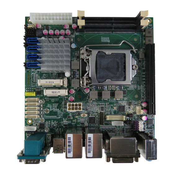
- Page 1 MITX-SLS0/KLS0 Series Industrial Motherboard in Mini-ITX Form Factor with ® 6th / 7th Generation Intel Core™ i Processor User’s Guide...
- Page 2 © 2016 Quanmax Inc. All rights reserved. The information in this user’s guide is provided for reference only. Quanmax does not assume any liability arising out of the application or use of the information or products described herein. This user’s guide may contain or reference information and products protected by copyrights or patents and does not convey any license under the patent rights of Quanmax, nor the rights of others.
-
Page 3: Table Of Contents
Expansion Interfaces ................. 41 Memory Module Installation ............... 41 Chapter 4 AMI BIOS Setup ..................43 Overview ....................43 Main Menu ....................44 Advanced Menu..................45 Power Menu ....................58 Security Menu.................... 59 Boot Menu ....................60 MITX-SLS0/KLS0 Series User’s Manual... - Page 4 Content Save & Exit Menu ..................61 Chapter 5 Driver Installation ..................63 Appendix A DIO (Digital I/O) Sample Code ............64 Appendix B WatchDog Timer Sample Code ............. 67 MITX-SLS0/KLS0 Series User’s Manual...
-
Page 5: Figures
Figure 4 Jumper and Connector Locations ..........22 Figure 5 Front Panel IO ................26 Figure 6 Align the SO-DIMM Memory Module with the onboard socket ..42 Figure 7 Press down on the SO-DIMM Memory Module to lock it in place 42 MITX-SLS0/KLS0 Series User’s Manual... -
Page 6: Tables
Table 29 CN2 SIM Interface Wafer for MPCIE2 ......... 32 Table 30 CN3 USB2.0 Port 11, 12 Pin Header ........... 32 Table 31 CN4 USB2.0 Port 7, 8 Pin Header..........32 Table 32 CN5 Digital Input / Output Wafer ..........32 MITX-SLS0/KLS0 Series User’s Manual... - Page 7 Table 60 Advanced Menu – Super IO Configuration – Serial Port 5 Configuration ..................51 Table 61 Advanced Menu – Super IO Configuration – Serial Port 6 Configuration ..................52 Table 62 Advanced Menu – CPU Chipset Configuration ......53 MITX-SLS0/KLS0 Series User’s Manual...
- Page 8 Table 65 Advanced Menu – DIO Configuration .......... 56 Table 66 Advanced Menu – H/W Monitor ........... 57 Table 67 Power Menu ................58 Table 68 Security Menu ................59 Table 69 Boot Menu ................... 60 Table 70 Save & Exit Menu ................ 61 MITX-SLS0/KLS0 Series User’s Manual...
-
Page 9: Safety Instructions
Use extreme caution when installing or removing components. Refer to the installation instructions in this user’s guide for precautions and procedures. If you have any questions, please contact Quanmax Post-Sales Technical Support. WARNING High voltages are present inside the chassis when the unit’s power cord is plugged into an electrical outlet. -
Page 10: Preventing Electrostatic Discharge
Static electricity can harm system boards. Perform service at an ESD workstation and follow proper ESD procedure to reduce the risk of damage to components. Quanmax strongly encourages you to follow proper ESD procedure, which can include wrist straps and smocks, when servicing equipment. - Page 11 Handle components and boards with care. Don’t touch the components or contacts on a board. Hold a board by its edges or by its metal mounting bracket. Do not handle or store system boards near strong electrostatic, electromagnetic, magnetic, or radioactive fields. MITX-SLS0/KLS0 Series User’s Manual...
-
Page 12: Preface
Remove all items from the box. If any items listed on the purchase order are missing, notify Quanmax customer service immediately. Inspect the product for damage. If there is damage, notify Quanmax customer service immediately. Refer to “Warranty Policy” for the return procedure. -
Page 13: Warranty Policy
Quanmax or its authorized agent; or if the failure is caused by accident, acts of God, or other causes beyond the control of Quanmax or the manufacturer. Neglect, misuse, and abuse shall include any installation, operation, or maintenance of the product other than in accordance with the user’s guide. -
Page 14: Maintaining Your Computer
Quanmax. Limitation of Liability In no event shall Quanmax be liable for any defect in hardware, software, loss, or inadequacy of data of any kind, or for any direct, indirect, incidental, or consequential damages in connection with or arising out of the performance or use of any product furnished hereunder. - Page 15 Line conditioners keep a system’s AC power source voltage at a fairly constant level and, therefore, can handle brownouts. Because of this added protection, line conditioners cost more than surge protectors. However, line conditioners cannot protect against a complete loss of power. MITX-SLS0/KLS0 Series User’s Manual...
- Page 16 Surge protectors should be used with all UPS systems, and the UPS system should be Underwriters Laboratories (UL) safety approved. MITX-SLS0/KLS0 Series User’s Manual...
-
Page 17: Chapter 1 Introduction
Chapter 1 Introduction Overview The MITX-SLS0/KLS0 Series is a Mini-ITX form factor industrial-grade motherboard equipped with 6th / 7th Generation Intel® Skylake / Kaby Lake Core™ i Processors. It delivers greatly improved graphics performance, power efficiency and wireless connectivity in comparison with the models powered by the previous generation processors. -
Page 18: Product Specifications
1x 8-bit DIO (4-bit in and 4-bit out) AMI uEFI BIOS BIOS 1x 128Mb SPI flash memory onboard Input & Core Voltages monitoring Hardware Monitor CPU & System Temperatures monitoring Programable WDT to generate System reset event Watchdog MITX-SLS0/KLS0 Series User’s Manual... -
Page 19: System Block Diagram
0ºC ~ 60ºC / 32ºF ~ 140ºF (Standard) Operation Temp. -20ºC ~ 70ºC / -4ºF ~ 158ºF (Extended) CE, FCC Class A Certifications Table 1 Product Specifications System Block Diagram Figure 1 Block Diagram MITX-SLS0/KLS0 Series User’s Manual... -
Page 20: Mechanical Dimensions
Chapter 1 Mechanical Dimensions Figure 2 Mechanical Dimensions MITX-SLS0/KLS0 Series User’s Manual... -
Page 21: Chapter 2 Hardware Settings
No.1. To move a jumper from one position to another, use needle-nose pliers or tweezers to pull the pin cap off the pins and move it to the desired position. MITX-SLS0/KLS0 Series User’s Manual... -
Page 22: Jumper Settings And Pin Definitions
Chapter 3 Jumper Settings and Pin Definitions For jumper and connector locations, please refer to the diagrams below. Figure 4 Jumper and Connector Locations MITX-SLS0/KLS0 Series User’s Manual... -
Page 23: Jumper Settings
DIP 3P 1R MALE STRAIGHT TYPE Pitch:2.54mm [YIMTEX 3321*03SAGR(6T)] Table 4 JP2 Clear ME Register Jumper Description 1-2 Short Normal 2-3 Short Clear ME Register Pitch:2.54mm Table 5 JP3 RTC Reset Selection Jumper Description 1-2 Short Normal 2-3 Short Clear RTC CMOS Pitch:2.54mm MITX-SLS0/KLS0 Series User’s Manual... -
Page 24: Table 6 Jp4 Mpcie / Msata Selection For Mpcie2 (Models W/ Q170 Only)
6P 2R MALE 3322*03SAGR TYPE 180 P-2.54mm [YIMTEX 3322*03SAGR(6T)] Table 11 JP10 Backlight Power Enable Selection for LVDS1 Jumper Setting Status Backlight Enable Voltage = +3.3V Backlight Enable Voltage = +5V Active High Active Low SMD 6P 2R MALE TYPE 180D P-2.0mm[PINREX 222-97-03GBB1] MITX-SLS0/KLS0 Series User’s Manual... -
Page 25: Table 12 Jp11 Panel & Backlight Power Selection For Lvds1
Jumper Setting Description 1-2 Short COM1, Pin-9 = +12V 2-3 Short COM1, Pin-9 = +5V 3-4 Short COM1, Pin-9 = +5V 4-5 Short COM1, Pin-9 = RI DIP 5P 1R MALE STRAIGHT TYPE Pitch:2.54mm [YIMTEX 3321*05SAGR(6T)] MITX-SLS0/KLS0 Series User’s Manual... -
Page 26: Rear Panel Pin Assignments
Display Port A Connector Table 17 CN17 GbE LAN1 & USB3.0 Port-1, 2 Connector Signal Signal Signal +USBVCC +USBVCC MDI[0]+ USB_A- USB_A- MDI[0]- USB_A+ USB_A+ MDI[1]+ MDI[1]- USB3_SSRX- USB3_SSRX- MDI[2]+ USB3_SSRX+ USB3_SSRX+ MDI[2]- MDI[3]+ USB3_SSTX- USB3_SSTX- MDI[3]- USB3_SSTX+ USB3_SSTX+ MITX-SLS0/KLS0 Series User’s Manual... -
Page 27: Table 18 Cn18 Gbe Lan2 & Usb3.0 Port-3, 4 Connector
DVI-D Connector, Female, Right Angle, G/F Bright TIN, 5.8x13.0mm Screwlock Installed, All Ivory, Upper-PBT, Lower-PA66 [FEN YING DVITV200C112AE4DN1-F] Table 20 CN20 3 Stack-up Azalia Audio Phone Jack Signal Name BLUE LINE IN GREEN LINE OUT PINK MIC IN [Foxconn JA33331-H11P-4F] MITX-SLS0/KLS0 Series User’s Manual... -
Page 28: Table 21 Cn21 Usb2.0 Port-0,1 Type-A Connector
Half Full Port RS-232 RS-422 Duplex Duplex RS-485 RS-485 DATA- DATA+ Half Full Port RS-232 RS-422 Duplex Duplex RS-485 RS-485 DATA- DATA+ [FAN YING D20HB1102112PN] Note:RS-232 / 422 / 485 can be selected in BIOS setup. MITX-SLS0/KLS0 Series User’s Manual... -
Page 29: Table 23 Cn23 Display Port Connector
SMT type, 20-pin, Gold 30”, 90°, Tray [WIN WIN WDPE-20F3L1BU3] Table 24 CN24 Display Port Connector Signal Name Signal Name TX0+- TX3- TX0- TX1+ AUX+ TX1- TX2+ AUX- TX2- TX3+ SMT type, 20-pin, Gold 30”, 90°, Tray [WIN WIN WDPE-20F3L1BU3] MITX-SLS0/KLS0 Series User’s Manual... -
Page 30: Main Board Pin Assignments
Serial ATA Port-0 Connector SATA2 Serial ATA Port-1 Connector SATA3 Serial ATA Port-2 Connector SATA4 Serial ATA Port-3 Connector DIMM1 DDR4 Memory SO-DIMM Socket DIMM2 DDR4 Memory SO-DIMM Socket LVDS1 Primary 24-bit, 2-channel LVDS Panel Connector MITX-SLS0/KLS0 Series User’s Manual... -
Page 31: Table 26 Atx1 2X12-Pin Atx Power Supply Wafer
Table 28 CN1 USB3.0 Port-5, 6 Box Header (models w/ Q170 only) Signal Name Signal Name USBA_VBUS USBA_RX- USBB_VBUS USBA_RX+ USBB_RX- USBB_RX+ USBA_TX- USBA_TX+ USBB_TX- USBB_TX+ USBA_D- USBA_D+ USBB_D- USBB_D+ MALE DIP 20P 2R 180D P-2.0mm remove PIN 20 [PINREX 52X-80-20GU52] MITX-SLS0/KLS0 Series User’s Manual... -
Page 32: Table 29 Cn2 Sim Interface Wafer For Mpcie2
DIP 10P 2R MALE STRAIGHT TYPE Pitch:2.54mm remove pin 9 [PINREX 210-72-05GY22] Table 32 CN5 Digital Input / Output Wafer Signal Name DIO_0 DIO_1 DIO_2 DIO_3 DIO_4 DIO_5 DIO_6 DIO_7 SMD 10P 1R 180D MALE P=1.25mm, Tin Plated, NY46, White Insulator [Pinrex 712-73-10TWB0] MITX-SLS0/KLS0 Series User’s Manual... -
Page 33: Table 33 Cn6 Serial Port 3 Wafer
DDC_CLK DIP 10P 2R MALE STRAIGHT TYPE Pitch:2.54mm remove pin 9 [PINREX 210-72-05GY22] Table 36 CN11 Left Channel 3W Audio AMP Output Wafer Signal Name Speaker+ Speaker- DIP 2P 180° Pitch=2.0mm WAFER [YIMTEX 503PW1*02STR & 503PW1*02ST-1R] MITX-SLS0/KLS0 Series User’s Manual... -
Page 34: Table 37 Cn12 Backlight Power Output Wafer For Lvds1
Signal Name MSCLK MSDAT* KBDAT KBCLK DIP 6P 180° Pitch=2.0mm WAFER [YIMTEX 503PW1*06ST-1R] Table 41 CN16 Right Channel 3W Audio AMP Output Wafer Signal Name Speaker+ Speaker- DIP 2P 180° Pitch=2.0mm WAFER [YIMTEX 503PW1*02STR & 503PW1*02ST-1R] MITX-SLS0/KLS0 Series User’s Manual... -
Page 35: Table 42 Fan1 Cpu Fan Wafer
Table 45 FP2 Front Panel Pin Header 2 Signal Signal Power LED + Power Button + Power Button - PWRBTN Power LED - SM_ALERT# PLED BAT_LOW# SMBus Data SM_ALERT# BAT_LOW# SM_DATA SMBus Clock SM_CLK DIP 10P 2R MALE STRAIGHT TYPE Pitch:2.54mm [PINREX 210-92-05GB01] MITX-SLS0/KLS0 Series User’s Manual... -
Page 36: Table 46 Mpcie2 Full Size Mpcie / Msata Socket (Models W/ H110 Have Mpcie Only)
Ground USB_D- Ground USB_D+ +3.3VSB Ground +3.3VSB LED_WWAN# Ground / NC* LED_WLAN# Reserved LED_WPAN# Reserved +1.5V Reserved Ground Reserved +3.3VSB SMD 52P 90D(F) MINI PCI-Express Connector, H:5.6mm, Gold Flash, Tape Reel [FOXCONN AS0B221-S56Q-7H] *:mPCIE / mSATA. MITX-SLS0/KLS0 Series User’s Manual... -
Page 37: Table 47 Mpcie1 Half Size Mpcie / Msata Socket (Models W/ H110 Have Mpcie Only)
USB_D- Ground USB_D+ +3.3VSB Ground +3.3VSB LED_WWAN# Ground / NC* LED_WLAN# Reserved LED_WPAN# Reserved +1.5V Reserved Ground Reserved +3.3VSB SMD 52P 90D(F) MINI PCI-Express Connector, H:9.9mm, 10u Gold Plating, Tape Reel [FOXCONN AS0B226-S99Q-7H] *:mPCIE / mSATA. MITX-SLS0/KLS0 Series User’s Manual... -
Page 38: Table 48 Peg1 Pcie Express X16 Slot
HSOP5 Ground HSON5 Ground Ground HSIP5 Ground HSIN5 HSOP6 Ground HSON6 Ground Ground HSIP6 Ground HSIN6 HSOP7 Ground HSON7 Ground Ground HSIP7 PRSNT2# HSIN7 Ground Ground HSOP8 Reserved HSON8 Ground Ground HSIP8 Ground HSIN8 HSOP9 Ground MITX-SLS0/KLS0 Series User’s Manual... -
Page 39: Table 49 Sata1,2,3,4 Serial Ata Port-3,2,1,0 Connector
Table 49 SATA1,2,3,4 Serial ATA Port-3,2,1,0 Connector Signal Name DIP SATA-7P 180D CONN. BLUE/double row pin/parallel positioning peg [WIN WIN WATM-07ABN4A2B8UW4] Table 50 DIMM1,2 DDR4 Memory SO-DIMM Socket SMD SO DIMM 260P DDR4 Vertical [FOXCONN ATMD097-AED4S-4F] MITX-SLS0/KLS0 Series User’s Manual... -
Page 40: Table 51 Lvds1 Primary 24-Bit, 2-Channel Lvds Panel Connector
TxoutB0- TxoutA0- TxoutB0+ TxoutA0+ TxoutB1- TxoutA1- TxoutB1+ TxoutA1+ TxoutB2- TxoutA2- TxoutB2+ TxoutA2+ TxoutB3- TxoutA3- TxoutB3+ TxoutA3+ DDC_Clock DDC_Data SMD MALE 30P 180° 2ROWS Pitch:1.25mm Tin Plated [HOMETOM WF30H6-7AJA178] *:LVDS1 panel power can be selected by JP3 MITX-SLS0/KLS0 Series User’s Manual... -
Page 41: Chapter 3 System Installation
Do not touch the connectors of the SO-DIMM. Dirt or other residue may cause a malfunction. Hold the SO-DIMM with its notch aligned with the memory socket of the board and insert it at a 30-degree angle into the socket. MITX-SLS0/KLS0 Series User’s Manual... -
Page 42: Figure 6 Align The So-Dimm Memory Module With The Onboard Socket
SO-DIMM. Lift it out of the socket. Make sure you store the SO-DIMM in an anti-static bag. The socket must be populated with memory modules of the same size and manufacturer. MITX-SLS0/KLS0 Series User’s Manual... -
Page 43: Chapter 4 Ami Bios Setup
This chapter provides a description of the AMI BIOS. The BIOS setup menus and available selections may vary from those of your product. For specific information on the BIOS for your product, please contact Quanmax. NOTE: The BIOS menus and selections for your product may vary from those in this chapter. -
Page 44: Main Menu
Frequency 2133 MHz F1: General Help F2: Previous Values System date [Wed 04/06/2016] F3: Optimized Defaults System time [17:53:22] F4: Save & Reset ESC: Exit Access Level Administrator Version 2.17.1254. Copyright (C) 2016, American Megatrends, Inc. MITX-SLS0/KLS0 Series User’s Manual... -
Page 45: Advanced Menu
Version 2.17.1254. Copyright (C) 2016, American Megatrends, Inc. Onboard LAN 1 Controller Options: Disabled, Enabled Onboard LAN 1 Boot Options: Disabled, Enabled Onboard LAN 2 Controller Options: Disabled, Enabled Onboard LAN 2 Boot Options: Disabled, Enabled Audio Controller Options: Disabled, Enabled MITX-SLS0/KLS0 Series User’s Manual... -
Page 46: Table 54 Advanced Menu - Display Configuration
Options: 32M, 64M, 96M, 128M, 160M, 192M, 224M, 256M, 288M, 320M, 352M, 384M, 416M, 448M, 480M, 512M, 1024M DVMT Total Gfx Mem Options: 128M, 256M, MAX Primary IGFX Boot Display Options: VBIOS Default, CRT, DVI, DP, DP2 Active LVDS Options: Disabled, Enabled MITX-SLS0/KLS0 Series User’s Manual... -
Page 47: Table 55 Advanced Menu - Super Io Configuration
IO=2F8h; IRQ=3, 4, 5, 6, 7, 9, 10, 11, 12; IO=3E8h; IRQ=3, 4, 5, 6, 7, 9, 10, 11, 12; IO=2E8h; IRQ=3, 4, 5, 6, 7, 9, 10, 11, 12; Serial Port 1 Type Options: RS232, RS422, RS485 MITX-SLS0/KLS0 Series User’s Manual... -
Page 48: Table 57 Advanced Menu - Super Io Configuration - Serial Port
IO=2F8h; IRQ=3, 4, 5, 6, 7, 9, 10, 11, 12; IO=3E8h; IRQ=3, 4, 5, 6, 7, 9, 10, 11, 12; IO=2E8h; IRQ=3, 4, 5, 6, 7, 9, 10, 11, 12; Serial Port Type Options: RS232, RS422, RS485 MITX-SLS0/KLS0 Series User’s Manual... -
Page 49: Table 58 Advanced Menu - Super Io Configuration - Serial Port
IO=2E8h; IRQ=3, 4, 5, 6, 7, 9, 10, 11, 12; IO=2F0h; IRQ=3, 4, 5, 6, 7, 9, 10, 11, 12; IO=2E0h; IRQ=3, 4, 5, 6, 7, 9, 10, 11, 12; Serial Port Type Options: RS232, RS422, RS485 MITX-SLS0/KLS0 Series User’s Manual... -
Page 50: Table 59 Advanced Menu - Super Io Configuration - Serial Port
IO=3E8h; IRQ=3, 4, 5, 6, 7, 9, 10, 11, 12; IO=2E8h; IRQ=3, 4, 5, 6, 7, 9, 10, 11, 12; IO=2F0h; IRQ=3, 4, 5, 6, 7, 9, 10, 11, 12; IO=2E0h; IRQ=3, 4, 5, 6, 7, 9, 10, 11, 12; MITX-SLS0/KLS0 Series User’s Manual... -
Page 51: Table 60 Advanced Menu - Super Io Configuration - Serial Port
IO=3E8h; IRQ=3, 4, 5, 6, 7, 9, 10, 11, 12; IO=2E8h; IRQ=3, 4, 5, 6, 7, 9, 10, 11, 12; IO=2F0h; IRQ=3, 4, 5, 6, 7, 9, 10, 11, 12; IO=2E0h; IRQ=3, 4, 5, 6, 7, 9, 10, 11, 12; MITX-SLS0/KLS0 Series User’s Manual... -
Page 52: Table 61 Advanced Menu - Super Io Configuration - Serial Port
IO=3E8h; IRQ=3, 4, 5, 6, 7, 9, 10, 11, 12; IO=2E8h; IRQ=3, 4, 5, 6, 7, 9, 10, 11, 12; IO=2F0h; IRQ=3, 4, 5, 6, 7, 9, 10, 11, 12; IO=2E0h; IRQ=3, 4, 5, 6, 7, 9, 10, 11, 12; MITX-SLS0/KLS0 Series User’s Manual... -
Page 53: Table 62 Advanced Menu - Cpu Chipset Configuration
Options: Disabled, Enabled Hyper-threading Options: Disabled, Enabled VT-d Options: Disabled, Enabled Active Processor Cores Options: All, 1, 2, 3 Limit CPUID Maximum Options: Disabled, Enabled Execute Disable Bit Options: Disabled, Enabled Intel® Virtualization Technology Options: Disabled, Enabled MITX-SLS0/KLS0 Series User’s Manual... -
Page 54: Table 63 Advanced Menu - Sata Configuration
Options: Disabled, Enabled Serial ATA Port 3 Port 3 Options: Disabled, Enabled Serial ATA Port 4 Port 4 Options: Disabled, Enabled mSATA Port 1 Port 1 Options: Disabled, Enabled mSATA Port 2 Port 2 Options: Disabled, Enabled MITX-SLS0/KLS0 Series User’s Manual... -
Page 55: Table 64 Advanced Menu - Usb Configuration
USB Mass Storage Driver Support [Enabled] ESC: Exit Version 2.17.1254. Copyright (C) 2016, American Megatrends, Inc. Legacy USB Support Options: Enabled, Disabled, Auto XHCI hand-off Options: Enabled, Disabled USB Mass Storage Driver Support Options: Disabled, Enabled MITX-SLS0/KLS0 Series User’s Manual... -
Page 56: Table 65 Advanced Menu - Dio Configuration
Options: Output Low, Output High, Input DIO_3 Options: Output Low, Output High, Input DIO_4 Options: Output Low, Output High, Input DIO_5 Options: Output Low, Output High, Input DIO_6 Options: Output Low, Output High, Input DIO_7 Options: Output Low, Output High, Input MITX-SLS0/KLS0 Series User’s Manual... -
Page 57: Table 66 Advanced Menu - H/W Monitor
Version 2.17.1254. Copyright (C) 2016, American Megatrends, Inc. CPU Warning Temperature Options: Disabled, 80 C, 85 C, 90 C, 95 C Smart FAN Configuration CPU FAN Setting Options: Manual, Smart System FAN Setting Options: Manual, Smart MITX-SLS0/KLS0 Series User’s Manual... -
Page 58: Power Menu
Options: Disabled, Enabled Resume By PCI-E Device Options: Disabled, Enabled Resume By Ring Device Options: Disabled, Enabled Resume By RTC Alarm Options: Disabled, Enabled WatchDog Timer Configuration WDT Function Options: Disabled, Enabled WDT Count Mode Options: Second, Minute MITX-SLS0/KLS0 Series User’s Manual... -
Page 59: Security Menu
F2: Previous Values The password length must be in the following range: F3: Optimized Defaults Minimum Length F4: Save & Reset Maximum length ESC: Exit Administrator Password User Password Version 2.17.1254. Copyright (C) 2016, American Megatrends, Inc. MITX-SLS0/KLS0 Series User’s Manual... -
Page 60: Boot Menu
Version 2.17.1254. Copyright (C) 2016, American Megatrends, Inc. Full Screen LOGO Display Options: Disabled, Enabled Bootup Numlock State Options: On, Off CSM Support Options: Enabled, Disabled Boot Option Filter Options: UEFI and Legacy, Legacy only, UEFI only MITX-SLS0/KLS0 Series User’s Manual... -
Page 61: Save & Exit Menu
Enter: Select +/-: Change Opt. Save Options F1: General Help Save Changes F2: Previous Values Discard Changes F3: Optimized Defaults F4: Save & Reset Restore Defaults ESC: Exit Version 2.17.1254. Copyright (C) 2016, American Megatrends, Inc. MITX-SLS0/KLS0 Series User’s Manual... - Page 62 Load Optimal Default values for all the setup values. This option allows you to load failsafe default values for each of the parameters on the Setup menus, which will provide the most stable performance settings. The F8 key can be used for this operation. MITX-SLS0/KLS0 Series User’s Manual...
-
Page 63: Chapter 5 Driver Installation
After you have finished assembling your system and connected the appropriate power source, power it up using the power supply and install the desired operating system. You can download the drivers for the MITX-SLS0/KLS0 Series from the Quanmax website at www.quanmax.com and install as instructed there. -
Page 64: Appendix A Dio (Digital I/O) Sample Code
// DIO_6 : GP36 // DIO_7 : GP37 //**************************************************************// #include<stdio.h> #define INDEX_PORT 0x2E #define DATA_PORT INDEX_PORT+1 void Set_SIO_Reg( int REG, int DATA) outportb(INDEX_PORT, REG); outportb(DATA_PORT, DATA); int Get_SIO_Reg(int REG) int Result; outportb(INDEX_PORT, REG); Result = inportb(DATA_PORT); MITX-SLS0/KLS0 Series User’s Manual... - Page 65 //Set DIO_0~7 as Input Set_SIO_Reg(0xEC, 0xFF); //Read DIO_0~7 value RetVal = Get_SIO_Reg(0xED); printf("Read DIO_0~7 value\n"); for (i=0; i<8; i++) Temp = (RetVal>>i) & 0x01; printf("DIO_%d = %d\n",i ,Temp); system("pause"); Set_SIO_Reg(0xEC, 0x00); printf("Set DIO_0~7 to High\n"); Set_SIO_Reg(0xED, 0xFF); system("pause"); MITX-SLS0/KLS0 Series User’s Manual...
- Page 66 Appendix A printf("Set DIO_0~7 to Low\n"); Set_SIO_Reg(0xED, 0x00); system("pause"); return 0; MITX-SLS0/KLS0 Series User’s Manual...
-
Page 67: Appendix B Watchdog Timer Sample Code
//Please compile with Turbo C 3.0 to utilized the program //========================================================== ==========// #include<stdio.h> #define SIO_CONFIG_INDEX 0x2e #define SIO_CONFIG_DATA SIO_CONFIG_INDEX+1 void UnlockSIO() outp(SIO_CONFIG_INDEX,0x87); outp(SIO_CONFIG_INDEX,0x87); void LockSIO() outp(SIO_CONFIG_INDEX,0xAA); void SetLDN(int LDN) outp(SIO_CONFIG_INDEX, 0x07); outp(SIO_CONFIG_DATA, LDN); void main() int value = 0; UnlockSIO(); SetLDN(0x08); //Enable WDT outp(SIO_CONFIG_INDEX,0x30); MITX-SLS0/KLS0 Series User’s Manual... - Page 68 //Set Timer unit(0xF0 bit3(0: 1sec, 1: 60 sec) of watchdog timer by setting this bit) outp(SIO_CONFIG_INDEX,0xF0); value=inp(SIO_CONFIG_DATA); outp(SIO_CONFIG_DATA,(value & 0xF7));//set unit sec. //Set Timer Value(0xF1 Time of watchdog timer) outp(SIO_CONFIG_INDEX,0xF1); outp(SIO_CONFIG_DATA,0x14);//set to 20 sec (0x14) LockSIO(); MITX-SLS0/KLS0 Series User’s Manual...
Need help?
Do you have a question about the MITX-SLS0/KLS0 Series and is the answer not in the manual?
Questions and answers