
Subscribe to Our Youtube Channel
Related Manuals for Quanmax KEMX-1750 series


Summary of Contents for Quanmax KEMX-1750 series
- Page 1 KEMX-1750 Series ® Intel BayTrail Processors User’s Guide KEMX-1750 series Use r’s Manual...
- Page 2 © 2011 Quanmax Inc. All rights reserved. The information in this user’s guide is provided for reference only. Quanmax does not assume any liability arising out of the application or use of the information or products described herein. This user’s guide may contain or reference information and products protected by copyrights or patents and does not convey any license under the patent rights of Quanmax, nor the rights of others.
- Page 3 Memory Module Installation ................38 Chapter 4 AMI BIOS Setup ....................39 Overview ........................39 Main Menu ......................40 Ad vanced Menu ....................41 Boot Menu......................54 Security Menu .......................55 Save & Exit Menu ....................55 KEMX-1750 series Use r’s Manual...
-
Page 4: Kemx-1750 Series Use R's Manual
Content Chapter 5 Driver Installation .....................57 Appendix A DIO (Digital I/O) Sample Code ..............58 Appendix B WatchDog Timer Sample Code ..............61 KEMX-1750 series Use r’s Manual... - Page 5 Figure 5 Rear IO ....................33 Figure 6 Expansion Interfaces................37 Figure 7 Align the SO-DIMM Memory Module with the onb oard socket ..38 Figure 8 Press down on the SO-DIMM Memory Module to lock it in place .38 KEMX-1750 series Use r’s Manual...
- Page 6 Tables Tables Table 1 KEMX-1750 series Specification............18 Table 2 Jumper List ....................23 Table 3 JP1 Panel & Backlight Power Selection for LVDS1 ......23 Table 4 JP2 Backlight Power Enable Selection for LVDS1......23 Table 5 JP3 AT / ATX Mode Selection ..............23 Table 6 JP4 LVDS1_ Backlight DC/PWM Selection ........24...
- Page 7 Table 58 Ad vanced Menu –DIO Configuration ..........51 Table 59 Ad vanced Menu –H/W Monitor ............52 Table 60 Power Configuration ................53 Table 61 Boot Menu ....................54 Table 62 Security Menu ..................55 Table 63 Save & Exit Menu..................55 KEMX-1750 series Use r’s Manual...
-
Page 8: Safety Instructions
Use extreme caution when installing or removing components. Refer to the installation instructions in this user’s guide for precautions and procedures. If you have any questions, please contact Quanmax Post-Sales Technical Support. WARNING High voltages are present inside the chassis when the unit’s power cord is plugged into an electrical outlet. -
Page 9: Preventing Electrostatic Discharge
Static electricity can harm system boards. Perform service at an ESD workstation and follow proper ESD procedure to reduce the risk of damage to components. Quanmax strongly encourages you to follow proper ESD procedure, which can include wrist straps and smocks, when servicing equipment. - Page 10 Handle components and boards with care. Don’t touch the components or contacts on a board. Hold a board by its edges or by its metal mounting bracket. Do not handle or store system boards near strong electrostatic, electromagnetic, magnetic, or radioactive fields. KEMX-1750 series Use r’s Manual...
-
Page 11: How To Use This Guide
Remove all items from the box. If any items listed on the purchase order are missing, notify Quanmax customer service immediately. Inspect the product for damage. If there is damage, notify Quanmax customer service immediately. Refer to “Warranty Policy” for the return procedure. -
Page 12: Warranty Policy
Quanmax or its authorized agent; or if the failure is caused by accident, acts of God, or other causes beyond the control of Quanmax or the manufacturer. Neglect, misuse, and abuse shall include any installation, operation, or maintenance of the product other than in accordance with the user’s guide. -
Page 13: Maintaining Your Computer
Quanmax. Limitation of Liability In no event shall Quanmax be liable for any defect in hardware, software, loss, or inadequacy of data of any kind, or for any direct, indirect, incidental, or consequential damages in connection with or arising out of the performance or use of any product furnished hereunder. - Page 14 AC power is lost, the battery can provide power to the system for a limited amount of time, depending on the UPS system. UPS systems range in price from a few hundred dollars to several thousand KEMX-1750 series Use r’s Manual...
- Page 15 Surge protectors should be used with all UPS systems, and the UPS system should be Underwriters Laboratories (UL) safety approved. KEMX-1750 series Use r’s Manual...
-
Page 16: Chapter 1 Introduction
Chapter 1 Chapter 1 Introduction Overview The KEMX-1750 series is a Mini-ITX form factor industrial motherboard combining ® Intel BayTrail Processors. Featured are 2x DDR3L, 2 x GbE LANs, 6x COM, 5 x USB 2.0, 1x USB 3.0, 1x VGA, 1x HDMI, 1 x PS/2 KB&MS, 1 x Parallel port, 1x... -
Page 17: Product Specifications
1x Header for mPCIe activity LED support 1x mPCIe Socket (half size) 1x PCIEx1 Slot Expansion Slot 1x SIM card holder AMI uEFI BIOS BIOS 1x 64Mb SPI flash ROM onboard KEMX-1750 series Use r’s Manual... -
Page 18: Table 1 Kemx-1750 Series Specification
Storage Temp: -20°C ~ 80°C / -4°F ~ 176°F (Standard) Operation Temp. -40°C ~ 85°C / -40°F ~ 185°F ( Extended) Humidity: 0% ~ 95% Certifications CE, FCC Class A Table 1 KEMX-1750 series Specification KEMX-1750 series Use r’s Manual... -
Page 19: System Block Diagram
Chapter 1 System Block Diagram Figure 1 Block Diagram KEMX-1750 series Use r’s Manual... -
Page 20: Mechanical Dimensions
Chapter 1 Mechanical Dimensions Figure 2 Mechanical Dimensions KEMX-1750 series Use r’s Manual... -
Page 21: Chapter 2 Hardware Settings
No.1. To move a jumper from one position to another, use needle-nose pliers or tweezers to pull the pin cap off the pins and move it to the desired position. KEMX-1750 series Use r’s Manual... -
Page 22: Jumper Settings And Pin Definitions
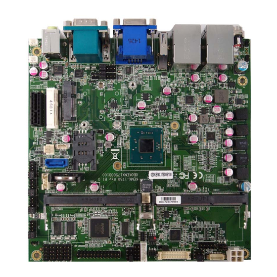
Chapter 2 Jumper Settings and Pin Definitions For jumper and connector locations, please refer to the diagrams below. Figure 4 Jumper and Connector Locations KEMX-1750 series Use r’s Manual... -
Page 23: Jumper Settings
Backlight Enable Voltage = +5V Active High Active Low Pitch: 2.54mm [Y IMTEX 3362*03SAGR] Table 5 JP3 AT / ATX Mode Selection Jumper Status 1-2 Short ATX Mode 2-3 Short AT Mode Pitch:2.54mm [YIMTEX 3321*03SAGR(6T)] KEMX-1750 series Use r’s Manual... -
Page 24: Table 6 Jp4 Lvds1_ Backlight Dc/Pwm Selection
USB pow er w ill be cut off in S4 & S5 state. 1-2 Short USB pow er is al w ays supply. Pitch:2.54mm [YIMTEX 3321*02SAGR(6T)] Table 11 JP15 RTC Reset Selection Jumper Status 1-2 Open Normal Operation 1-2 Short Clear RTC CMOS Pitch:2.54mm [YIMTEX 3321*02SAGR(6T)] KEMX-1750 series Use r’s Manual... -
Page 25: Internal Connector Pin Assignment
Primary 24-bit, 1-channel LVDS Panel Connector MPCIE1 Half Size Mini-PCIE Express v1.2 Socket PEG1 PCIE Express x1Slot SATA1 Serial ATA Port 0 Connector SATA2 Serial ATA Port-1 mSATA Socket (Full Size) LPT1 Parallel Port Pin Header KEMX-1750 series Use r’s Manual... -
Page 26: Table 12 Atx1 4-Pin Atx Power Input Connector
& BL_ADJ can be setting can be selected by JP4 BL_PWM & BL_ADJ can be setting from 0V to 5V in BIOS setup BL_PWM **:Backlight Power can be selected by JP1. ***:BL_EN can be selected by JP2. KEMX-1750 series Use r’s Manual... -
Page 27: Table 16 Cn2 Ps/2 Keyboard / Mouse Wafer
Pitch: 2.54mm [Y IMTEX 3322*05SAGR(6T] Table 18 CN5 USB2.0 Port DN1 Wafer Signal Name +VCCUSB_DN12 USBDN_1- USBDN_1+ Pitch: 1.25mm [Pinrex 712-73-04TWE0] Table 19 CN8 HDD Power Output Wafer Signal +12V Pitch: 2.0mm, Tin Plated, White Insulator [PINREX 721-93-04TWE9] KEMX-1750 series Use r’s Manual... -
Page 28: Table 20 Cn10 Right Channel 3W Audio Amp Output Wafer
Table 23 DIMM1 Primary DDR3 Memory SO-DIMM Socket [ARGOSY DDRSK-20401-TP9D] Table 24 DIMM2 Secondary DDR3 Memory SO-DIMM Socket [ARGOSY DDRSK-20401-TP9D] Table 25 FAN1 CPU FAN Wafer Signal +12V* FAN_RPM Pitch: 2.54mm WAFER [YIMTEX 521AW1*03ST-1R] *:PWM Fan control supported. KEMX-1750 series Use r’s Manual... -
Page 29: Table 26 Fan2 System Fan Wafer
Signal Name VDD_EN +3.3V / +5V* +3.3V / +5V* TxclkA- TxclkA+ TxoutA0- TxoutA0+ TxoutA1- TxoutA1+ TxoutA2- TxoutA2+ TxoutA3- TxoutA3+ DDC_CLK DDC_Data Pitch:1.25mm Tin Plated [HIROSE DF13-30DP-1.25(24)] *:LVDS1 panel pow er can be selected by JP4. KEMX-1750 series Use r’s Manual... -
Page 30: Table 30 Mpcie1 Half Size Mini-Pcie Express V1.2 Socket
Ground +1.5V Ground SMB_CLK PETn0 SMB_DATA PETp0 Ground Ground USB_D- Ground USB_D+ +3.3VSB Ground +3.3VSB LED_WWAN# Ground LED_WLAN# Reserved LED_WPAN# Reserved +1.5V Reserved Ground Reserved +3.3VSB [FOXCONN AS0B226-S99Q-7H] *:These pins are connected to SIM1 directly KEMX-1750 series Use r’s Manual... -
Page 31: Table 31 Peg1 Pcie Express X1 Slot
SLOT,DIP PCI 18*2P EXPRESS 180D( F) Black [ Win Win WPES--036AN41B22UWS] LEA D FREE Table 32 SATA1 Serial ATA Port 0 Connector Signal Nam e DIP SATA-7P 180D CONN. BLUE / double row pin/parallel positioning peg [WIN WIN WATM-07ABN4A2B8UW4] KEMX-1750 series Use r’s Manual... -
Page 32: Table 33 Sata2 Serial Ata Port-1 Msata Socket
H:5.6mm, Gold Flash, Au 1-3u”, Black, Tape Reel [LOTES AAA-PCI-046-K01] Table 34 LPT1 Pin Header Signal Name Signal Name #AFD #ERR #INIT #SLIN #ACK BUSY SLCT DIP 26P 2R MALE 180° Pitch:2.54mm Remove PIN 26 [PINREX 210-72-13GB11] KEMX-1750 series Use r’s Manual... -
Page 33: Rear Panel Pin Assignments
Table 37 CN4 LAN1 & USB2.0 Port 0,1 Connector Signal Signal MDI[0]+ +USBVCC MDI[0]- USB_A- MDI[1]+ USB_A+ MDI[1]- MDI[2]+ +USBVCC MDI[2]- USB_B- MDI[3]+ USB_B+ MDI[3]- [UDE RU1-161F9WGF(XB)] *:The power source of +USBVCC can be selected by JP13. KEMX-1750 series Use r’s Manual... -
Page 34: Table 38 Cn6 Lan2 & Usb2.0 Port 2,3 Connector
Acti vity Yellow LED blink Table 39 USB1 USB3.0 Port 0 Connector Signal Nam e Signal Nam e +USBVCC * USB_RX- USB_D- USB_RX+ USB_D+ USB_TX- USB_TX+ COLOR:BLUE [FOXCONN UEA3119C-4FB1-4F] *:The power source of +USBVCC can be selected by JP13 KEMX-1750 series Use r’s Manual... -
Page 35: Table 40 Vga Db-15 Vga Connector
TMDS Data2+ Ground TMDS Data2– TMDS Data1+ Ground TMDS Data1– TMDS Data0+ Ground TMDS Data0– TMDS Clock+ Ground TMDS Clock– Reserved Reserved DDC_CLK DDC_DATA Ground +5 V Power Hot Plug Detect [ ZI HUI 282-1921Q30243] KEMX-1750 series Use r’s Manual... -
Page 36: Table 42 Cn9 Rs-232 / 422 / 485 Port 1, 2 Connector
Note:RS-232 / 422 / 485 can be selected in BIOS setup. Table 43 DIO1 3 Stack-up Azalia Audio Phone Jack Signal Name GREEN LINE OUT PINK MIC IN JACK*2 DIP 9P 90D AZALIA.D3.5mm [KORTAK ZJ387S-9B-7H] KEMX-1750 series Use r’s Manual... -
Page 37: System Installation
When adding or removing expansion cards, make sure that you unplug the power supply first. Meanwhile, read the documentation for the expansion card to configure any necessary hardware or software settings for the expansion card, such as jumpers, switches or BIOS configuration. KEMX-1750 series Use r’s Manual... -
Page 38: Memory Module Installation
SO-DIMM. Lift it out of the socket. Make sure you store the SO-DIMM in an anti-static bag. The socket must be populated with memory modules of the same size and manufacturer. KEMX-1750 series Use r’s Manual... -
Page 39: Ami Bios Setup
This chapter provides a description of the AMI BIOS. The BIOS setup menus and available selections may vary from those of your product. For specific information on the BIOS for your product, please contact Quanmax. NOTE: The BIOS menus and selections for your product may vary from those in this chapter. -
Page 40: Main Menu
F3: Optimized Defaults Frequenc y 1333 MHz F4 Save & Exit Sys tem date [Mon 12/01/2014] ESC Exit Sys tem ti me [17:23:12] Access Level Admi nistrator Version 2.16.1242. C opyright (C) 2013, American M egatrends, Inc. KEMX-1750 series Use r’s Manual... -
Page 41: Advanced Menu
Version 2.16.1242. C opyright (C) 2013, American M egatrends, Inc. Onboard LAN 1 Controller Options: Disabled, Enabled Onboard LAN 1 Boot Options: Disabled, Enabled Onboard LAN 2 Controller Options: Disabled, Enabled Onboard LAN 2 Boot Options: Disabled, Enabled Audio Controller Options: Disabled, Enabled KEMX-1750 series Use r’s Manual... -
Page 42: Table 46 Ad Vanced Menu – Display Configuration
Options:64M, 96M, 128M, 160M, 192M, 224M, 256M, 288M, 320M, 352M, 384M, 416M, 448M, 480M, 512M DVMT Total Gfx Mem Options: 128M, 256M, MAX Primary IGFX Boot Displa y Options: VBIOS Default, CRT, HDMI, LVDS Active LVDS Options: Disabled, Enabled KEMX-1750 series Use r’s Manual... -
Page 43: Table 47 Ad Vanced Menu – Super Io Configuration
IO=2F8h; IRQ=3, 4, 5, 6, 7, 9, 10, 11, 12; IO=3E8h; IRQ=3, 4, 5, 6, 7, 9, 10, 11, 12; IO=2E8h; IRQ=3, 4, 5, 6, 7, 9, 10, 11, 12; Serial Port Type Options: RS232, RS422, RS485 KEMX-1750 series Use r’s Manual... -
Page 44: Table 49 Ad Vanced Menu – Super Io Configuration – Serial Port
IO=2F8h; IRQ=3, 4, 5, 6, 7, 9, 10, 11, 12; IO=3E8h; IRQ=3, 4, 5, 6, 7, 9, 10, 11, 12; IO=2E8h; IRQ=3, 4, 5, 6, 7, 9, 10, 11, 12 Serial Port Type Options: RS232, RS422, RS485 KEMX-1750 series Use r’s Manual... -
Page 45: Table 50 Ad Vanced Menu – Super Io Configuration – Serial Port
IO=3E8h; IRQ=3, 4, 5, 6, 7, 9, 10, 11, 12; IO=2E8h; IRQ=3, 4, 5, 6, 7, 9, 10, 11, 12; IO=2F0h; IRQ=3, 4, 5, 6, 7, 9, 10, 11, 12; IO=2E0h; IRQ=3, 4, 5, 6, 7, 9, 10, 11, 12; KEMX-1750 series Use r’s Manual... -
Page 46: Table 51 Ad Vanced Menu – Super Io Configuration – Serial Port
IO=3E8h; IRQ=3, 4, 5, 6, 7, 9, 10, 11, 12; IO=2E8h; IRQ=3, 4, 5, 6, 7, 9, 10, 11, 12; IO=2F0h; IRQ=3, 4, 5, 6, 7, 9, 10, 11, 12; IO=2E0h; IRQ=3, 4, 5, 6, 7, 9, 10, 11, 12; KEMX-1750 series Use r’s Manual... -
Page 47: Table 52 Ad Vanced Menu – Super Io Configuration – Serial Port
IO=3E8h; IRQ=3, 4, 5, 6, 7, 9, 10, 11, 12; IO=2E8h; IRQ=3, 4, 5, 6, 7, 9, 10, 11, 12; IO=2F0h; IRQ=3, 4, 5, 6, 7, 9, 10, 11, 12; IO=2E0h; IRQ=3, 4, 5, 6, 7, 9, 10, 11, 12; KEMX-1750 series Use r’s Manual... -
Page 48: Device Mode
IO=378h; IRQ= 5, 6, 7, 9, 10, 11, 12; IO=278h; IRQ=5, 6, 7, 9, 10, 11, 12; IO=38ch; IRQ=5, 6, 7, 9, 10, 11, 12; Device Mode Options: STD Printer Mode, SPP Mode, EPP 1-9 and SPP Mode1-7 KEMX-1750 series Use r’s Manual... -
Page 49: Table 55 Ad Vanced Menu –Cpu Advanced Configuration
A Port 1 Empty ESC Exit Port 1 [ Enabled ] Version 2.16.1242. C opyright (C) 2013, American M egatrends, Inc. SATA Options: Disabled, Enabled SATA Mode Options: IDE Mode, AHCI Mode Port 1 Options: Disabled, Enabled KEMX-1750 series Use r’s Manual... -
Page 50: Table 57 Ad Vanced Menu –Usb Configuration
Legacy USB Support Options: Disabled, Enabled, Auto XHCI Legacy Support Options: Disabled, Enabled XHCI hand-off Options: Disabled, Enabled EHCI hand-off Options: Disabled, Enabled USB Mass Storage Driver Support Options: Disabled, Enabled xHCI Mode Options: Smart Auto, Enabled KEMX-1750 series Use r’s Manual... -
Page 51: Table 58 Ad Vanced Menu –Dio Configuration
F1: General H elp F2: Previous Values DO-1 F3: Optimized Defaults F4 Save & Exit DO-2 ESC Exit DO-3 DO-4 Version 2.16.1242. C opyright (C) 2013, American M egatrends, Inc. USER Configuration Options: Disabled, Enabled KEMX-1750 series Use r’s Manual... -
Page 52: Table 59 Ad Vanced Menu –H/W Monitor
CPU Warning Temperature Options: Disabled, 80, 85, 90, 95 Smart FAN Configuration CPU FAN Setting [Manual Mode] Options: Manual Mode, Smart Mode Manual Duty 255 FAN Setting [Manual Mode] Options: Manual Mode, Smart Mode Manual Duty 255 KEMX-1750 series Use r’s Manual... -
Page 53: Acpi Sleep State
Resume From S3 By PS/2 Mouse Options: Disabled, Enabled Resume By PCIE Device Options: Disabled, Enabled Resume By RTC Alarm Options: Disabled, Enabled EUP Power Saving Mode Options: Disabled, Enabled Watchdog Timer Configuration [Disabled] WDT Function ■ Options: Disabled, Enabled KEMX-1750 series Use r’s Manual... -
Page 54: Boot Menu
Full Screen LOGO Display Options: Disabled, Enabled Bootup Numlock State Options: On, Off Keyboard Detect Warning Options: Disabled, Enabled CSM Support Options: Disabled, Enabled Boot Option Filter Options: UEFI and Legacy, Legacy only, UEFI only KEMX-1750 series Use r’s Manual... -
Page 55: Security Menu
+- Change Opt. Save C hanges F1: General H elp Discard Changes F2: Previous Values F3: Optimized Defaults Restore Defaults F4 Save & Exit ESC Exit Version 2.16.1242. C opyright (C) 2013, American M egatrends, Inc. KEMX-1750 series Use r’s Manual... - Page 56 Load Optimal Default values for all the setup values. This option allows you to load failsafe default values for each of the parameters on the Setup menus, which will provide the most stable performance settings. The F8 key can be used for this operation. KEMX-1750 series Use r’s Manual...
-
Page 57: Driver Installation
After you have finished assembling your system and connected the appropriate power source, power it up using the power supply and install the desired operating system. You can download the drivers for the KEMX-1750 series from the Quanmax website www.quanmax.com and install as instructed there. For other operating systems, please contact Quanmax. - Page 58 #define GPIO2_SEL 0xA4 #define GPIO2_LVL 0xA8 #define SET_IO32(IoAddr, dSet) outpd(IoAddr, inpd(IoAddr) | (dSet)) #define RESET_IO32(IoAddr, Rst) outpd(IoAddr, inpd(IoAddr) &~ (Rst)) #define READ_IO32(IoAddr) inpd(IoAddr) DWORD inpd(int portid) DWORD dwRet; asm mov dx, portid; asm lea bx, dwRet; KEMX-1750 series Use r’s Manual...
- Page 59 DWORD gGpioLvValue = 0; int i = 0; //Read DI_0~3 value printf("Read DI_O~3 value\n"); for (i=0; i< 4; i++) gGpioLvValue = READ_IO32(GPIO_BASE + GPIO2_LVL); gGpioLvValue &= (0x01 << gDioGpio[i]); printf("DI_%d = %d\n",i ,gGpioLvValue > 0); system("pause"); KEMX-1750 series Use r’s Manual...
- Page 60 Appendix A //set DO_0~3 to High printf("Set DO_0~3 to High\n"); outpd(GPIO_BASE + GPIO2_LVL, 0 xFFFFFFFF); system("pause"); //set DO_0~3 to Low printf("Set DO_0~3 to Low\n"); outpd(GPIO_BASE + GPIO2_LVL, 0 x0); system("pause"); return 0; KEMX-1750 series Use r’s Manual...
-
Page 61: Watchdog Timer Sample Code
//********************************************************************** //========================================================== ==========// //KEMX-1750 DOS Watchdog sample program //Please compile with Turbo C 3.0 to utilized the program //========================================================== ==========// #include<stdio.h> #define SIO_CONFIG_INDEX 0x2e #define SIO_CONFIG_DATA SIO_CONFIG_INDEX+1 void UnlockSIO() outp(SIO_CONFIG_INDEX,0 x87); outp(SIO_CONFIG_INDEX,0 x87); void LockSIO() KEMX-1750 series Use r’s Manual... - Page 62 //Set Timer unit(0xF0 bit3(0: 1sec, 1: 60 sec) of watchdog timer by setting this bit) outp(SIO_CONFIG_INDEX,0 xF0); value=inp(SIO_CONFIG_DATA); outp(SIO_CONFIG_DATA,(value & 0xF7));//set unit sec. //Set Timer Value(0xF1 Time of watchdog timer) outp(SIO_CONFIG_INDEX,0 xF1); outp(SIO_CONFIG_DATA,0x14);//set to 20 sec (0x14) LockSIO(); KEMX-1750 series Use r’s Manual...
Need help?
Do you have a question about the KEMX-1750 series and is the answer not in the manual?
Questions and answers