
Related Manuals for Quanmax KEEX-6100


Summary of Contents for Quanmax KEEX-6100
- Page 1 KEEX-6100 Industrial ECX Embedded SBC with 2nd generation Intel® core i3/i5/i7 processor User’s Guide KEEX-6100 User’s Manual...
- Page 2 © 2011 Quanmax Inc. All rights reserved. The information in this user’s guide is provided for reference only. Quanmax does not assume any liability arising out of the application or use of the information or products described herein. This user’s guide may contain or reference information and products protected by copyrights or patents and does not convey any license under the patent rights of Quanmax, nor the rights of others.
-
Page 3: Table Of Contents
Memory Module Installation ............... 37 Chapter 4 AMI BIOS Setup ..................39 Overview ....................39 Main Menu ....................40 Advanced Menu ..................41 Boot Menu ....................52 Security Menu .................... 53 Save & Exit Menu ..................53 KEEX-6100 User’s Manual... - Page 4 Content Chapter 5 Driver Installation ................. 55 Appendix A DIO (Digital I/O) Sample Code ............56 Appendix B WatchDog Timer Sample Code ............58 KEEX-6100 User’s Manual...
-
Page 5: Figures
Figure 4 Jumper and Connector Locations ..........23 Figure 5 Rear Panel IO ................26 Figure 6 Align the SO-DIMM Memory Module with the onboard socket ..37 Figure 7 Press down on the SO-DIMM Memory Module to lock it in place 38 KEEX-6100 User’s Manual... -
Page 6: Tables
Tables Tables Table 1 KEEX-6100 Specification ............... 18 Table 2 Jumper List ..................24 Table 3 JP1 ME F/W Selection ..............24 Table 4 JP2 Panel & Backlight Power Selection for LVDS2 ....... 24 Table 5 JP3 Panel Backlight Power Selection for LVDS1 ......25 Table 6 JP4 Backlight Power Enable Selection for LVDS1 ...... - Page 7 Table 56 Advanced Menu – AMT Configuration ......... 48 Table 57 Advanced Menu –USB Configuration .......... 50 Table 58 Advanced Menu –H/W Monitor ............ 51 Table 59 Boot Menu ................... 52 Table 60 Security Menu ................53 Table 61 Save & Exit Menu ................ 53 KEEX-6100 User’s Manual...
-
Page 8: Safety Instructions
Use extreme caution when installing or removing components. Refer to the installation instructions in this user’s guide for precautions and procedures. If you have any questions, please contact Quanmax Post-Sales Technical Support. WARNING High voltages are present inside the chassis when the unit’s power cord is plugged into an electrical outlet. -
Page 9: Preventing Electrostatic Discharge
Static electricity can harm system boards. Perform service at an ESD workstation and follow proper ESD procedure to reduce the risk of damage to components. Quanmax strongly encourages you to follow proper ESD procedure, which can include wrist straps and smocks, when servicing equipment. - Page 10 Handle components and boards with care. Don’t touch the components or contacts on a board. Hold a board by its edges or by its metal mounting bracket. Do not handle or store system boards near strong electrostatic, electromagnetic, magnetic, or radioactive fields. KEEX-6100 User’s Manual...
-
Page 11: Preface
Remove all items from the box. If any items listed on the purchase order are missing, notify Quanmax customer service immediately. Inspect the product for damage. If there is damage, notify Quanmax customer service immediately. Refer to “Warranty Policy” for the return procedure. -
Page 12: Warranty Policy
Quanmax or its authorized agent; or if the failure is caused by accident, acts of God, or other causes beyond the control of Quanmax or the manufacturer. Neglect, misuse, and abuse shall include any installation, operation, or maintenance of the product other than in accordance with the user’s guide. -
Page 13: Maintaining Your Computer
Quanmax. Limitation of Liability In no event shall Quanmax be liable for any defect in hardware, software, loss, or inadequacy of data of any kind, or for any direct, indirect, incidental, or consequential damages in connection with or arising out of the performance or use of any product furnished hereunder. - Page 14 Line conditioners keep a system’s AC power source voltage at a fairly constant level and, therefore, can handle brownouts. Because of this added protection, line conditioners cost more than surge protectors. However, line conditioners cannot protect against a complete loss of power. KEEX-6100 User’s Manual...
- Page 15 Surge protectors should be used with all UPS systems, and the UPS system should be Underwriters Laboratories (UL) safety approved. KEEX-6100 User’s Manual...
-
Page 16: Chapter 1 Introduction
Chapter 1 Introduction Overview The KEEX-6100 is an ECX Form Factor embedded single board computer (SBC) that equips the latest 2 generation Intel® Core™ i3/i5/i7 processors with the high integration of the Intel® QM67/ HM65 chipset. Featured are DDR3 1066/1333 SO-DIMM up to 8GB, 2x 24-bit LVDS, HDMI, DP, VGA, 2x Gigabit Ethernet, 2x SATA, mini PCIe slot, 8x USB 2.0, 2x COM ports with Power Selection, HD audio and... -
Page 17: Product Specifications
2x 2x5-in pitch 2.54 mm headers for 4x USB 2.0 ports onboard for internal use. 2x COM ports supported 2x 1x10-pin pitch 1.27 mm wafer connectors onboard for COM1 and COM2 COM1 with RS-232/422/485 supported. COM2 with RS-232 only. KEEX-6100 User’s Manual... -
Page 18: Table 1 Keex-6100 Specification
ATX/ AT Mode Supported Windows XP/XPe/Windows 7 OS Supported 0ºC – 60ºC Operation Temp. -20ºC – 80ºC Storage Temp. 0% – 95% RH Humidity CE, FCC Class A Certifications Table 1 KEEX-6100 Specification KEEX-6100 User’s Manual... -
Page 19: System Block Diagram
Chapter 1 System Block Diagram Figure 1 Block Diagram KEEX-6100 User’s Manual... -
Page 20: Mechanical Dimensions
Chapter 1 Mechanical Dimensions KEEX-6100 User’s Manual... -
Page 21: Figure 2 Mechanical Dimensions
Chapter 1 Figure 2 Mechanical Dimensions KEEX-6100 User’s Manual... -
Page 22: Chapter 2 Hardware Settings
No.1. To move a jumper from one position to another, use needle-nose pliers or tweezers to pull the pin cap off the pins and move it to the desired position. KEEX-6100 User’s Manual... -
Page 23: Jumper Settings And Pin Definitions
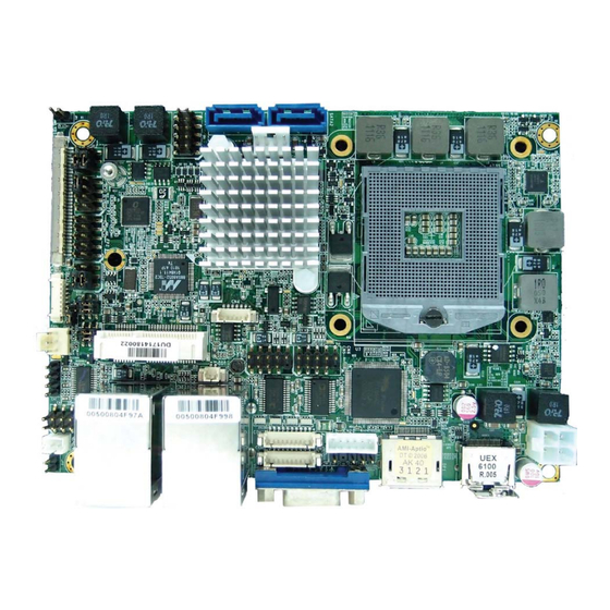
Chapter 2 Jumper Settings and Pin Definitions For jumper and connector locations, please refer to the diagrams below. Figure 4 Jumper and Connector Locations KEEX-6100 User’s Manual... -
Page 24: Jumper Settings
ME F/W Disabled. Pitch:2.54mm [YIMTEX 3321*02SAGR(6T)] Table 4 JP2 Panel & Backlight Power Selection for LVDS2 Jumper Setting Function Backlight Power = +12V Backlight Power = +5V Panel Power = +3.3V Panel Power = +5V Pitch:2.54mm [YIMTEX 3362*03SAGR] KEEX-6100 User’s Manual... -
Page 25: Table 5 Jp3 Panel Backlight Power Selection For Lvds1
Table 9 JP7 SRTC Reset Selection Jumper Status 1-2 Open Normal Operation 1-2 Short Clear ME Registers Pitch:2.54mm [YIMTEX 3321*02SAGR(6T)] Table 10 JP8 RTC Reset Selection Jumper Status 1-2 Open Normal Operation 1-2 Short Clear RTC CMOS Pitch:2.54mm [YIMTEX 3321*02SAGR(6T)] KEEX-6100 User’s Manual... -
Page 26: Rear Panel Pin Assignments
+USBVCC MDI[2]- USB_B- MDI[3]+ USB_B+ MDI[3]- [UDE RU1-161F9WGF(XB)] Table 13 CN10 LAN2 & USB 2.0 Port 8, 9 Connector Signal Signal MDI[0]+ +USBVCC MDI[0]- USB_A- MDI[1]+ USB_A+ MDI[1]- MDI[2]+ +USBVCC MDI[2]- USB_B- MDI[3]+ USB_B+ MDI[3]- [UDE RU1-161F9WGF(XB)] KEEX-6100 User’s Manual... -
Page 27: Table 14 Dp1 Display Port Connector
TMDS Clock– Reserved Reserved DDC_CLK DDC_DATA Ground +5 V Power Hot Plug Detect [Foxconn QJ51193-HEB4-4F] Table 16 VGA1 DB-15 VGA Connector Signal Name Signal Name Green Blue DDC data HSYNC VSYNC DDC clock [ FEN YING SM1003S01012PN] KEEX-6100 User’s Manual... -
Page 28: Main Board Pin Assignments
Serial ATA Port 0 Connector SATA2 Serial ATA Port 1 Connector Table 18 ATX2 +12V Power Input Connector Signal Name +12V +12V Pitch:4.2mm [YIMTEX 576MWA2*02STR] Table 19 CR2032 Battery Power Input Wafer Signal Name +VBAT Pitch:1.25mm [Pinrex 712-73-02TWR0] KEEX-6100 User’s Manual... -
Page 29: Table 20 Cfd1 Cf Type Ii Connector
PCSEL Reset IDE IDEIORDY SDA2 DREQ IDE Address 1 DACK# IDE Address 0 IDE activity IDE Data 0 PDIAG# IDE Data 1 IDE Data 8 IDE Data 2 IDE Data 9 IOIS16# IDE Data 10 [KINGFON CFCMD-45T15W100] KEEX-6100 User’s Manual... -
Page 30: Table 21 Com1 Rs-232/422/485 Port 1 Wafer
Digital Input 0 Digital Output 1 Digital Input 1 Digital Output 2 Digital Input 2 Digital Output 3 Digital Input 3 Pitch:2.54mm [YIMTEX 3362*05SANGR] Table 24 CN2 SATA HDD Power Output Wafer Signal Name +12V Pitch:2.5mm [YIMTEX 512CW4ST-2R] KEEX-6100 User’s Manual... -
Page 31: Table 25 Cn3 Backlight Power Output Wafer For Lvds1
Table 27 CN5 USB 2.0 Port 2, 3 Pin Header Signal Name Signal Name +USBVCC +USBVCC USB_A- USB_B- USB_A+ USB_B+ Pitch:2.54mm [YIMTEX 3362*05SANGR-09] Table 28 CN6 USB 2.0 Port 10, 11 Pin Header Signal Name Signal Name +USBVCC +USBVCC USB_A- USB_B- USB_A+ USB_B+ Pitch:2.54mm [YIMTEX 3362*05SANGR-09] KEEX-6100 User’s Manual... -
Page 32: Table 29 Cn7 S/Pdif Pin Header
Signal Name BL_EN*** +5V / +12V ** +5V / +12V ** BL_ADJ_VOL * BL_ADJ_PWM * Pitch:1.25mm [YIMTEX 501MW1X07MTR-1R] *:BL_ADJ can be setting in BIOS setup. **:Backlight Power can be selected by JP2. ***:BL_EN can be selected by JP5 KEEX-6100 User’s Manual... -
Page 33: Table 34 Cn20 Keyboard & Mouse Wafer
Power LED + Power Button + PWRBTN Power Button - PLED Power LED - Keyboard Lock SMBus Data KLOCK SMBus Clock Pitch:2.54mm [YIMTEX 3362*05SANGR] Table 39 IR1 IrDA Pin Header Signal Name IR_Rx IR_Tx Pitch:2.54mm [YIMTEX 3321*05SAGR(6T)-02] KEEX-6100 User’s Manual... -
Page 34: Table 40 Lvds1 Primary 24-Bit, 2-Channel Lvds Panel Connector
LVDS_A2+ LVDS_BCLK+ LVDS_B3-/NC LVDS_ACLK- LVDS_B3+/NC LVDS_ACLK+ LVDS_A3-/NC DDC_DATA LVDS_A3+/NC VDDEN LVDS_B0- DDC_CLK LVDS_B0+ +3.3V / +5V * +3.3V / +5V * LVDS_B1- +3.3V / +5V * Pitch:1.0mm [JAE FI-X30SSL-HF] *: Panel Power can be selected by JP2. KEEX-6100 User’s Manual... -
Page 35: Table 42 Mpcie1 Mini-Pcie Express V 1.2 Socket
Ground +1.5V Ground SMB_CLK PETn0 SMB_DATA PETp0 Ground Ground USB_D- Ground USB_D+ +3.3VSB Ground +3.3VSB LED_WWAN# Ground LED_WLAN# Reserved LED_WPAN# Reserved +1.5V Reserved Ground Reserved +3.3VSB Height:9.9mm [FOXCONN AS0B226-S99Q-7H] *: These pins are connected to CN4 directly. KEEX-6100 User’s Manual... -
Page 36: Table 43 Sata1 Serial Ata Port 0 Connector
Chapter 2 Table 43 SATA1 Serial ATA Port 0 Connector Signal Name [FOXCONN LD1807V-S52U] Table 44 SATA2 Serial ATA Port 1 Connector Signal Name [FOXCONN LD1807V-S52U] KEEX-6100 User’s Manual... -
Page 37: Chapter 3 System Installation
Do not touch the connectors of the SO-DIMM. Dirt or other residue may cause a malfunction. Hold the SO-DIMM with its notch aligned with the memory socket of the board and insert it at a 30-degree angle into the socket. Figure 6 Align the SO-DIMM Memory Module with the onboard socket KEEX-6100 User’s Manual... -
Page 38: Figure 7 Press Down On The So-Dimm Memory Module To Lock It In Place
SO-DIMM. Lift it out of the socket. Make sure you store the SO-DIMM in an anti-static bag. The socket must be populated with memory modules of the same size and manufacturer. KEEX-6100 User’s Manual... -
Page 39: Chapter 4 Ami Bios Setup
This chapter provides a description of the AMI BIOS. The BIOS setup menus and available selections may vary from those of your product. For specific information on the BIOS for your product, please contact Quanmax. NOTE: The BIOS menus and selections for your product may vary from those in this chapter. -
Page 40: Main Menu
2048 MB (DDR3) +- Change Opt. Frequency 1067 MHz F1: General Help F2: Previous Values System date [Wed 07/06/2011] F3: Optimized Defaults System time [17:21:40] F4 Save & Exit ESC Exit Version 2.10.1208. Copyright (C) 2010, American Megatrends, Inc. KEEX-6100 User’s Manual... -
Page 41: Advanced Menu
F3: Optimized Defaults >H/W Monitor F4 Save & Exit ESC Exit Version 2.10.1208. Copyright (C) 2010, American Megatrends, Inc. Onboard LAN Controller Options: Disabled, Enabled Onboard LAN Boot Options: Disabled, Enabled Audio Controller Options: Disabled, Enabled, Auto KEEX-6100 User’s Manual... -
Page 42: Table 47 Advanced Menu - Display Configuration
Boot Type Options: Disabled, CRT, LVDS1, HDMI, DP, LVDS2 Active LVDS1 Options: Disabled, Enabled LVDS1 Panel Type Options: VBIOS Default, 1024x768 LVDS, 1280x1024 LVDS, 1366x768 LVDS, 1920x1080 LVDS LVDS1 Panel Color Depth Options: 18 Bit, 24 Bit KEEX-6100 User’s Manual... -
Page 43: Table 48 Advanced Menu - Super Io Configuration
>Serial Port 2 Configuration Select Screen ↑↓ Select Item Enter: Select +- Change Opt. F1: General Help F2: Previous Values F3: Optimized Defaults F4 Save & Exit ESC Exit Version 2.10.1208. Copyright (C) 2010, American Megatrends, Inc. KEEX-6100 User’s Manual... -
Page 44: Table 49 Advanced Menu - Super Io Configuration - Serial Port
Device Mode [Standard Serial Po…] Enter: Select +- Change Opt. F1: General Help F2: Previous Values F3: Optimized Defaults F4 Save & Exit ESC Exit Version 2.10.1208. Copyright (C) 2010, American Megatrends, Inc. Serial Port Options: Disabled, Enabled KEEX-6100 User’s Manual... -
Page 45: Table 51 Advanced Menu -Power Management Configuration
Resume From S By PS/2 keyboard Options: Disabled, Enabled Resume From S By PS/2 mouse Options: Disabled, Enabled Resume By PCIE Device Options: Disabled, Enabled Resume By RTC Alarm Options: Disabled, Enabled EUP Power Saving Mode Options: Disabled, Enabled Watchdog Timer Configuration KEEX-6100 User’s Manual... -
Page 46: Table 52 Advanced Menu -Cpu Advanced Configuration
Intel ® Virtualization Tech Options: Disabled, Enabled VT-d Options: Disabled, Enabled Intel ® Hyper Threading Tech Options: Disabled, Enabled Active Processor Cores Options: All, 1 Limit CPUID Maximum Options: Disabled, Enabled Execute Disable Bit Options: Disabled, Enabled KEEX-6100 User’s Manual... -
Page 47: Table 53 Advanced Menu -Trusted Computing
+- Change Opt. F1: General Help F2: Previous Values F3: Optimized Defaults F4 Save & Exit ESC Exit Version 2.10.1208. Copyright (C) 2010, American Megatrends, Inc. SATA Controller(s) Options: Disabled, Enabled SATA Mode Selection Options: IDE, AHCI, RAID KEEX-6100 User’s Manual... -
Page 48: Table 55 Advanced Menu -Intel Txt(Lt) Configuration
F2: Previous Values F3: Optimized Defaults F4 Save & Exit ESC Exit Version 2.10.1208. Copyright (C) 2010, American Megatrends, Inc. Intel AMT Options: Disabled, Enabled Intel AMT Setup Prompt Options: Disabled, Enabled BIOS Hotkey Pressed Options: Disabled, Enabled KEEX-6100 User’s Manual... - Page 49 AMT Wait Timer Options: 0 only Options: Disabled, Enabled Activate Remote Assistance Process Options: Disabled, Enabled USB Configure Options: Disabled, Enabled PET Progress Options: Disabled, Enabled Intel AMT SPI Protected Options: Disabled, Enabled Watchdog Options: Disabled, Enabled KEEX-6100 User’s Manual...
-
Page 50: Table 57 Advanced Menu -Usb Configuration
Version 2.10.1208. Copyright (C) 2010, American Megatrends, Inc. Legacy USB Support Options: Disabled, Enabled, Auto EHCI hand-off Options: Disabled, Enabled USB Transfer Time-Out Options: 1, 5, 10, 20 sec. Device Transfer Time-Out Options: 10, 20, 30, 40 sec. Device Power-Up Delay Options: Auto, Manual KEEX-6100 User’s Manual... -
Page 51: Table 58 Advanced Menu -H/W Monitor
Version 2.10.1208. Copyright (C) 2010, American Megatrends, Inc. CPU Warning Temperature Options: Disabled, 80 C, 85 C, 90 C, 95 C CPU Shutdown Temperature Options: Disabled, 80 C, 85 C, 90 C, 95 C CPU Smart Fan Options: Disabled, Enabled KEEX-6100 User’s Manual... -
Page 52: Boot Menu
Version 2.10.1208. Copyright (C) 2010, American Megatrends, Inc. Full Screen LOGO Display Options: Disabled, Enabled Bootup Numlock State Options: On, Off Boot Option #1 Options: SATA: WDC WD6402AAEX-00Z3A0, Disabled Hard Drive BBS Priorities Boot Option #1: SATA: Maxtor 6L120M0, Disabled KEEX-6100 User’s Manual... -
Page 53: Security Menu
Save as User Defaults Restore User Defaults Enter: Select +- Change Opt. Boot Override F1: General Help SATA: WDC WD6402AAEX-00Z3A0 F2: Previous Values F3: Optimized Defaults F4 Save & Exit ESC Exit Version 2.10.1208. Copyright (C) 2010, American Megatrends, Inc. KEEX-6100 User’s Manual... - Page 54 Load Optimal Default values for all the setup values. This option allows you to load failsafe default values for each of the parameters on the Setup menus, which will provide the most stable performance settings. The F8 key can be used for this operation. KEEX-6100 User’s Manual...
-
Page 55: Chapter 5 Driver Installation
You can download the drivers for the KEEX-6100 from the Quanmax website www.quanmax.com and install as instructed there. For other operating systems, please contact Quanmax. - Page 56 Appendix A Appendix A DIO (Digital I/O) Sample Code //*************************************************************** //KEEX-6100 DOS DIO sample program //Please compile with Turbo C 3.0 to utilized the program //0:Low 1:High //DI_1: IOport 0x50C bit2 DO_1: IOport 0x539 bit4 //DI_2: IOport 0x50C bit3 DO_2: IOport 0x539 bit5...
- Page 57 //DO_3 is bit 6 outp(0x539,RetVal); RetVal=inp(0x53B);//IO Port: 0x53B RetVal=(RetVal|0x01);//DO_4 is bit 0 outp(0x53B,RetVal); system("pause"); //Reading DI_1~4 RetVal=inp(0x50C);//IO Port: 0x50C RetVal=(RetVal&0x3C);//DI_1 is bit 2 //DI_2 is bit 3 //DI_3 is bit 4 //DI_4 is bit 5 printf("DI_= %d\n",RetVal); system("pause"); return 0; KEEX-6100 User’s Manual...
- Page 58 Appendix B Appendix B WatchDog Timer Sample Code //============================================ //KEEX-6100 DOS Watchdog sample program //Please compile with Turbo C 3.0 to utilized the program //============================================ #include<stdio.h> int main() int value; //Initialized the WDT program outp(0x2E,0x87); outp(0x2E,0x87); //Setting Logical Device Number to 0x07 outp(0x2E,0x07);...
- Page 59 Appendix B outp(0x2E,0xF0); outp(0x2F,0x81);//bit7 WDTRST# output is enabled return 0; KEEX-6100 User’s Manual...
Need help?
Do you have a question about the KEEX-6100 and is the answer not in the manual?
Questions and answers