Sign In
Upload
Manuals
Brands
Quanmax Manuals
Motherboard
MITX-SLS0/KLS0 Series
Quanmax MITX-SLS0/KLS0 Series Manuals
Manuals and User Guides for Quanmax MITX-SLS0/KLS0 Series. We have
1
Quanmax MITX-SLS0/KLS0 Series manual available for free PDF download: User Manual
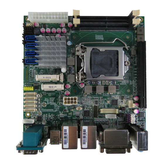
Quanmax MITX-SLS0/KLS0 Series User Manual (68 pages)
Industrial Motherboard in Mini-ITX Form Factor with 6th / 7th Generation Intel Core i Processor
Brand:
Quanmax
| Category:
Motherboard
| Size: 2.13 MB
Table of Contents
Table of Contents
3
Content
3
Figures
5
Tables
6
Safety Instructions
9
Before You Begin
9
When Working Inside a Computer
9
Preventing Electrostatic Discharge
10
Preface
12
How to Use this Guide
12
Unpacking
12
Regulatory Compliance Statements
12
Warranty Policy
13
Maintaining Your Computer
14
Chapter 1 Introduction
17
Overview
17
Product Specifications
18
System Block Diagram
19
Figure 1 Block Diagram
19
Table 1 Product Specifications
19
Mechanical Dimensions
20
Figure 2 Mechanical Dimensions
20
Chapter 2 Hardware Settings
21
Overview
21
Figure 3 Jumper Connector
21
Jumper Settings and Pin Definitions
22
Figure 4 Jumper and Connector Locations
22
Jumper Settings
23
Table 2 Jumper List
23
Table 3 JP1 at / ATX Power Mode Selection
23
Table 4 JP2 Clear ME Register
23
Table 5 JP3 RTC Reset Selection
23
Table 6 JP4 Mpcie / Msata Selection for MPCIE2 (Models W/ Q170 Only)
24
Table 7 JP5 Mpcie / Msata Selection for MPCIE1 (Models W/ Q170 Only)
24
Table 8 JP6 Keyboard Lock Selection
24
Table 9 JP7 MPCIE LED Indicator Pin Header
24
Table 11 JP10 Backlight Power Enable Selection for LVDS1
24
Table 12 JP11 Panel & Backlight Power Selection for LVDS1
25
Table 13 JP12 Pin-9 Selection for COM1
25
Table 14 JP13 ME F/W Selection
25
Table 15 JP14 Pin-9 Selection for COM2
25
Rear Panel Pin Assignments
26
Figure 5 Front Panel IO
26
Table 16 Rear Panel Connector List
26
Table 17 CN17 Gbe LAN1 & USB3.0 Port-1, 2 Connector
26
Table 18 CN18 Gbe LAN2 & USB3.0 Port-3, 4 Connector
27
Table 19 CN19 DVI-D Connector
27
Table 20 CN20 3 Stack-Up Azalia Audio Phone Jack
27
Table 21 CN21 USB2.0 Port-0,1 Type-A Connector
28
Table 22 CN22 RS-232 / 422 / 485 Port 1, 2 Connector
28
Table 23 CN23 Display Port Connector
29
Table 24 CN24 Display Port Connector
29
Main Board Pin Assignments
30
Table 25 Internal Connector List
30
Table 26 ATX1 2X12-Pin ATX Power Supply Wafer
31
Table 27 ATX2 2X4-Pin ATX Power Supply Wafer
31
Table 28 CN1 USB3.0 Port-5, 6 Box Header (Models W/ Q170 Only)
31
Table 29 CN2 SIM Interface Wafer for MPCIE2
32
Table 30 CN3 USB2.0 Port 11, 12 Pin Header
32
Table 31 CN4 USB2.0 Port 7, 8 Pin Header
32
Table 32 CN5 Digital Input / Output Wafer
32
Table 33 CN6 Serial Port 3 Wafer
33
Table 34 CN7~9 RS-232 Port 4, 5, 6 Wafer
33
Table 35 CN10 VGA Header
33
Table 36 CN11 Left Channel 3W Audio AMP Output Wafer
33
Table 37 CN12 Backlight Power Output Wafer for LVDS1
34
Table 38 CN13 Front Panel Audio Pin Header
34
Table 39 CN14 SPDIF-OUT Pin Header
34
Table 40 CN15 PS/2 Keyboard & Mouse Wafer
34
Table 41 CN16 Right Channel 3W Audio AMP Output Wafer
34
Table 42 FAN1 CPU FAN Wafer
35
Table 43 FAN2 System FAN Wafer
35
Table 44 FP1 Front Panel Pin Header 1
35
Table 45 FP2 Front Panel Pin Header 2
35
Table 46 MPCIE2 Full Size Mpcie / Msata Socket (Models W/ H110 Have Mpcie Only)
36
Table 47 MPCIE1 Half Size Mpcie / Msata Socket (Models W/ H110 Have Mpcie Only)
37
Table 48 PEG1 PCIE Express X16 Slot
38
Table 49 SATA1,2,3,4 Serial ATA Port-3,2,1,0 Connector
39
Table 50 DIMM1,2 DDR4 Memory SO-DIMM Socket
39
Table 51 LVDS1 Primary 24-Bit, 2-Channel LVDS Panel Connector
40
Chapter 3 System Installation
41
Expansion Interfaces
41
Memory Module Installation
41
Figure 6 Align the SO-DIMM Memory Module with the Onboard Socket
42
Figure 7 Press down on the SO-DIMM Memory Module to Lock It in Place
42
Chapter 4 AMI BIOS Setup
43
Overview
43
Main Menu
44
Table 52 BIOS Main Menu
44
Advanced Menu
45
Table 53 Advanced Menu
45
Table 54 Advanced Menu - Display Configuration
46
Table 55 Advanced Menu - Super IO Configuration
47
Table 56 Advanced Menu - Super IO Configuration - Serial Port
47
Table 57 Advanced Menu - Super IO Configuration - Serial Port
48
Table 58 Advanced Menu - Super IO Configuration - Serial Port
49
Table 59 Advanced Menu - Super IO Configuration - Serial Port
50
Table 60 Advanced Menu - Super IO Configuration - Serial Port
51
Table 61 Advanced Menu - Super IO Configuration - Serial Port
52
Table 62 Advanced Menu - CPU Chipset Configuration
53
Table 63 Advanced Menu - SATA Configuration
54
Table 64 Advanced Menu - USB Configuration
55
Table 65 Advanced Menu - DIO Configuration
56
Table 66 Advanced Menu - H/W Monitor
57
Power Menu
58
Table 67 Power Menu
58
Security Menu
59
Table 68 Security Menu
59
Boot Menu
60
Table 69 Boot Menu
60
Save & Exit Menu
61
Table 70 Save & Exit Menu
61
Chapter 5 Driver Installation
63
Appendix A DIO (Digital I/O) Sample Code
64
Appendix B Watchdog Timer Sample Code
67
Advertisement
Advertisement
Related Products
Quanmax MITX-DNV0 Series
Quanmax QBox Mini-1000 Series
Quanmax MoniQ-1500
Quanmax MoniQ-1700
Quanmax MoniQ-1900
Quanmax MITX-V1K0 Series
Quanmax Qbox Mini-2000 Series
Quanmax ATX-KLS0 Series
Quanmax ECX-KLU0 Series
Quanmax ECX-SLU0 Series
Quanmax Categories
Desktop
Touch Panel
Motherboard
Computer Hardware
Monitor
More Quanmax Manuals
Login
Sign In
OR
Sign in with Facebook
Sign in with Google
Upload manual
Upload from disk
Upload from URL