Table of Contents
Advertisement
Quick Links
Advertisement
Table of Contents

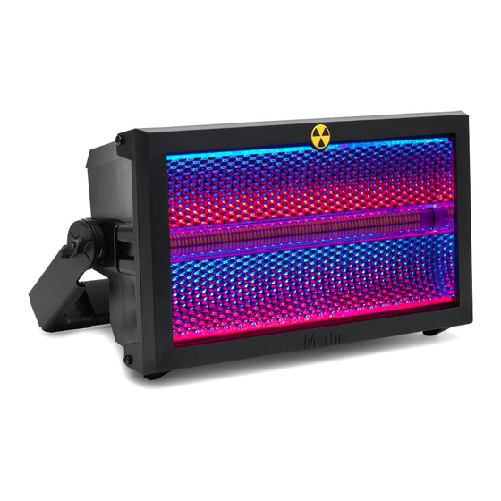
Summary of Contents for Martin Atomic 3000 LED
- Page 1 SERVICE MANUAL Atomic 3000 LED Revision A, 11-30-2017...
-
Page 2: Table Of Contents
Replacing the main PCB/UI .................................. 11 Replacing the air filters ..................................13 Replacing the fans ....................................13 Replacing the handle ....................................14 Calibrating the PSU ....................................15 Maintenance ................................18 Cleaning the product ....................................18 Conditions ......................................18 Maintenance schedule ..................................19 Atomic 3000 LED - Revision A, 11-30-2017 2 of 20... -
Page 3: General Information
• Small flatheaded screwdriver. Figure 2: Tools Important! Take the necessary precautions to prevent static electricity from damaging the product during modification or repair. Figure 3: ESD mat and wristband Atomic 3000 LED - Revision A, 11-30-2017 3 of 20... -
Page 4: Spare Parts
Service manual Spare parts For an overview of the spare parts and spare part numbers of Atomic 3000 LED, refer to martin.com Log in with your user login details. Search for “Atomic 3000 LED”. Clik “Partfinder: Layered” (1). Figure 4: PartFinder: Layered... -
Page 5: Troubleshooting
• Let the fixture cool down and restart it. PCB is at cut-off level. • If the ambient temperature is OK but the issue persists, replace the main LED assembly. Atomic 3000 LED - Revision A, 11-30-2017 5 of 20... -
Page 6: Wiring Diagram
Service manual Wiring diagram Figure 5: Wiring diagram, Atomic 3000 LED Atomic 3000 LED - Revision A, 11-30-2017 6 of 20 6 of 20... -
Page 7: Repair And Replacement
Replacing the back light reflector assembly Remove the front glass. See “Replacing the front glass” on page 7. Remove the two Torx20 screws (1) on each side. Figure 8: Removing the screws Atomic 3000 LED - Revision A, 11-30-2017 7 of 20... -
Page 8: Replacing The Back Light Led Pixel Board
Figure 10: Removing back light LED pixel board Replace the back light reflector LED pixel board (2). Follow the procedure in reverse order. Figure 11: Removing back light LED pixel board Atomic 3000 LED - Revision A, 11-30-2017 8 of 20... -
Page 9: Replacing The Main Light Engine Assembly
Figure 12: Removing the back light reflector ass. Remove the four Torx20 screws (2). Figure 13: Removing the four screws Remove the connector for the thermo switch (3) and temperature sensor (4). Figure 14: Disconnecting connectors Atomic 3000 LED - Revision A, 11-30-2017 9 of 20... -
Page 10: Replacing The Psu
36 digit calibration number (4) on the new PSU. Follow the procedure in reverse order. Calibrate the PSU. See “Calibrating the PSU” on page 15. Figure 17: Removing PSU board Atomic 3000 LED - Revision A, 11-30-2017 10 of 20... -
Page 11: Replacing The Main Pcb/Ui
Remove the two Torx10 screws (1). Figure 18: Removing the two screws Remove the nine connectors (2) from the mainboard. Figure 19: Removing nine connectors Remove the grounding wire (3). Figure 20: Removing grounding wire Atomic 3000 LED - Revision A, 11-30-2017 11 of 20... - Page 12 12. Follow the procedure in reverse order. NOTE! Be careful when you install the UI front cover. You need to slide it underneath the quarter- turn brackets. Figure 23: Removing the main PCB Atomic 3000 LED - Revision A, 11-30-2017 12 of 20...
-
Page 13: Replacing The Air Filters
Replacing the fans Remove the two Torx20 screws (1) on each fan assembly. Figure 25: Removing the Torx20 screws Gently remove the cover with a flatheaded screwdriver. Figure 26: Removing the cover Atomic 3000 LED - Revision A, 11-30-2017 13 of 20... -
Page 14: Replacing The Handle
10. Follow the procedure in reverse order. Figure 28: Removing screws on fans Replacing the handle Remove the knurled knob (1) on each side of the handle. Figure 29: Removing knurled knob Atomic 3000 LED - Revision A, 11-30-2017 14 of 20... -
Page 15: Calibrating The Psu
17 on page 10. Power up the product and let it boot up for five seconds. NOTE! The DMX address will be displayed after a successful boot up. Figure 32: Successful boot up Atomic 3000 LED - Revision A, 11-30-2017 15 of 20... - Page 16 Scroll down to SERVICE by pressing the DOWN arrow. Figure 35: Selecting SERVICE Press and hold the MENU button and wait until the ADVANCED SERVICE MENU is displayed. Figure 33: Accessing ADVANCED SERVICE MENU Atomic 3000 LED - Revision A, 11-30-2017 16 of 20...
- Page 17 13. Follow step 9 to 12 until you have changed all the digits in the calibration code. 14. Exit the menu by continuously pressing the LEFT button. Figure 37: Changing the digits in the code Atomic 3000 LED - Revision A, 11-30-2017 17 of 20...
-
Page 18: Maintenance
Maximum: +40° C (104° F). Clean Lubricate Daily “lamp on” hours: 12 hours. Adjust Voltage and frequency: 100-240 V, 50/60 Hz. Fan self-clean Update Martin by Harman ® Figure 40: Legend, maintenance schedule Atomic 3000 LED - Revision A, 11-30-2017 18 of 20... -
Page 19: Maintenance Schedule
LED lens LED board Back side SMPS Base fans C/SC C/SC C/SC C/SC C/SC C/SC C/SC C/SC C/SC C/SC Filters User interface Heat sink Wireset Fixture software Atomic 3000 LED - Revision A, 11-30-2017 19 of 20 19 of 20... - Page 20 Harman Professional Denmark ApS registered in the United States and/or other countries. Features, specifications, and appearance are subject to change without notice. Harman Professional Denmark ApS • Olof Palmes Allé 18 • 8200 Aarhus N • Denmark • www.martin.com Atomic 3000 LED - Revision A, 11-30-2017...


Need help?
Do you have a question about the Atomic 3000 LED and is the answer not in the manual?
Questions and answers